Dave's Dev Lab
-
Mr.Meseeks Says 'All Done!'
10/19/2017 at 22:34 • 0 comments![]()
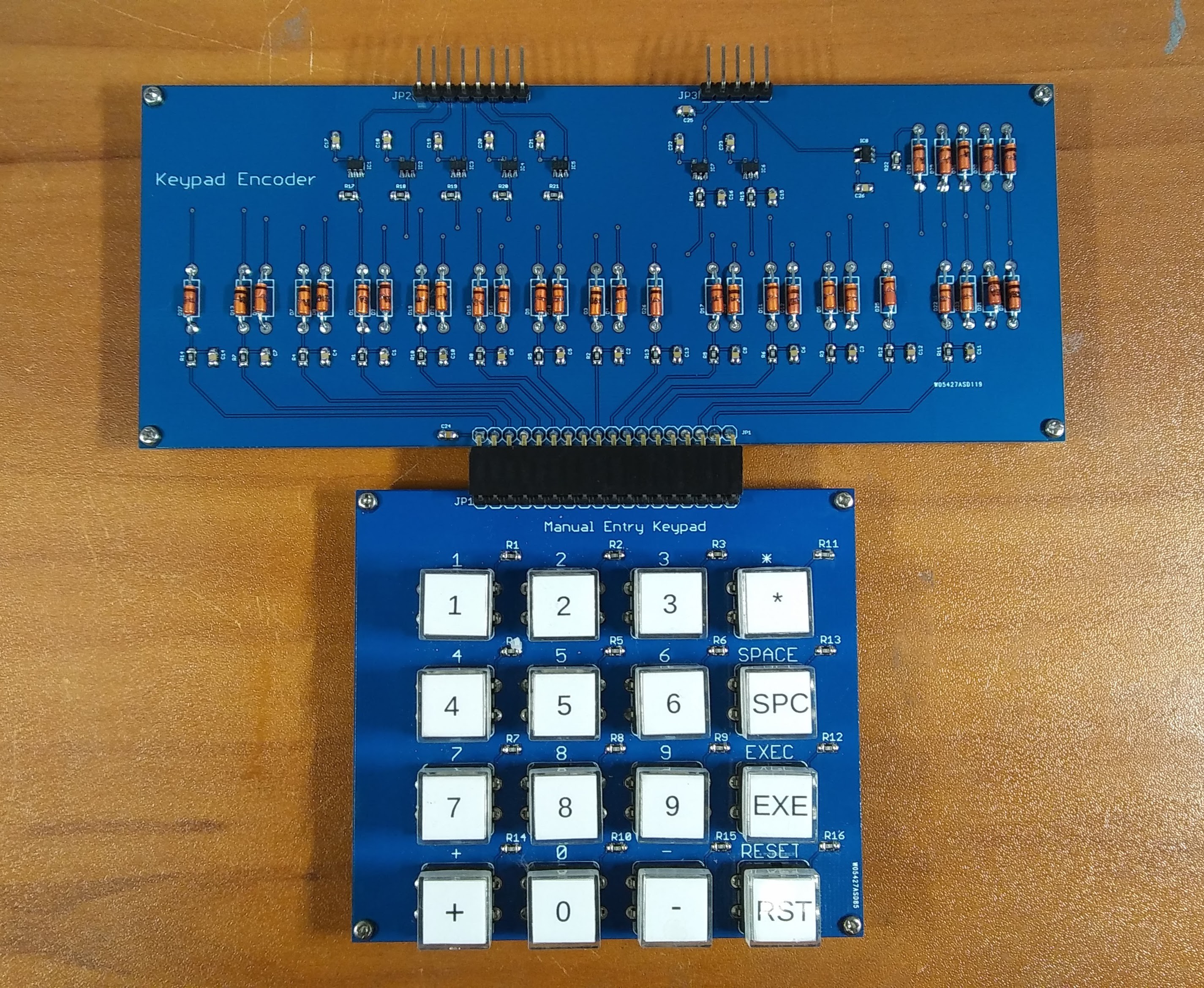
The new keypad encoder is 'All Done!'. It mates up directly with the male headers on the keypad PCB, so no need for cables to connect the two. When I design the laser cut acrylic for this section, I'll need to leave some tolerance for the screw holes so I can make sure it sits snuggle together.
-
Bending Diodes!
10/19/2017 at 20:48 • 0 comments![]()
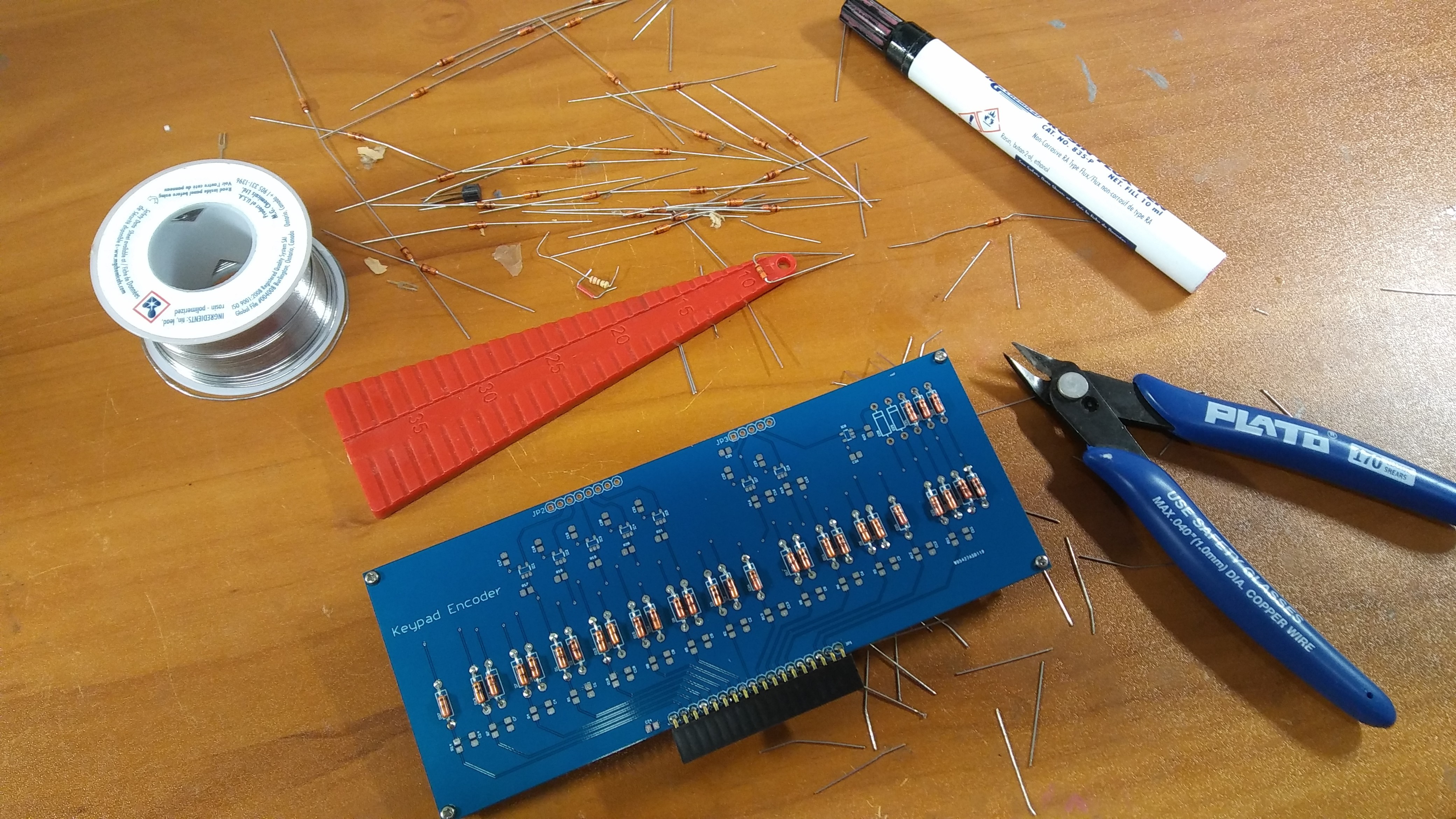
Well it's been a while since i had use for my "bending template"! I took a break from my "day job" work today to assemble the new keypad encoder. I again used the vintage diodes as discussed in an earlier log ( Keypad Encoder ). I kind of regret using them now as they make the board a lot bigger than it really needs to be, but it does add a nice look to the overall design. The keypad encoder breaks the key encoding into one connector that goes to each of the latches, and a separate connector for the reset, execute, and "key-up" signal. During the last round of integration testing ( You WILL be integrated! ), I realized that the keypad and the encoder really need to be close together, so instead of using male headers with female cables, I replace the male header with a female header. This will allow the two boards to be easily connected together with minimal wasted space. Back to bending diodes..... where is Bending Bender Rodriguez when you need him?
-
Happiness is New PCBs on a Monday
10/17/2017 at 22:54 • 2 comments![]()
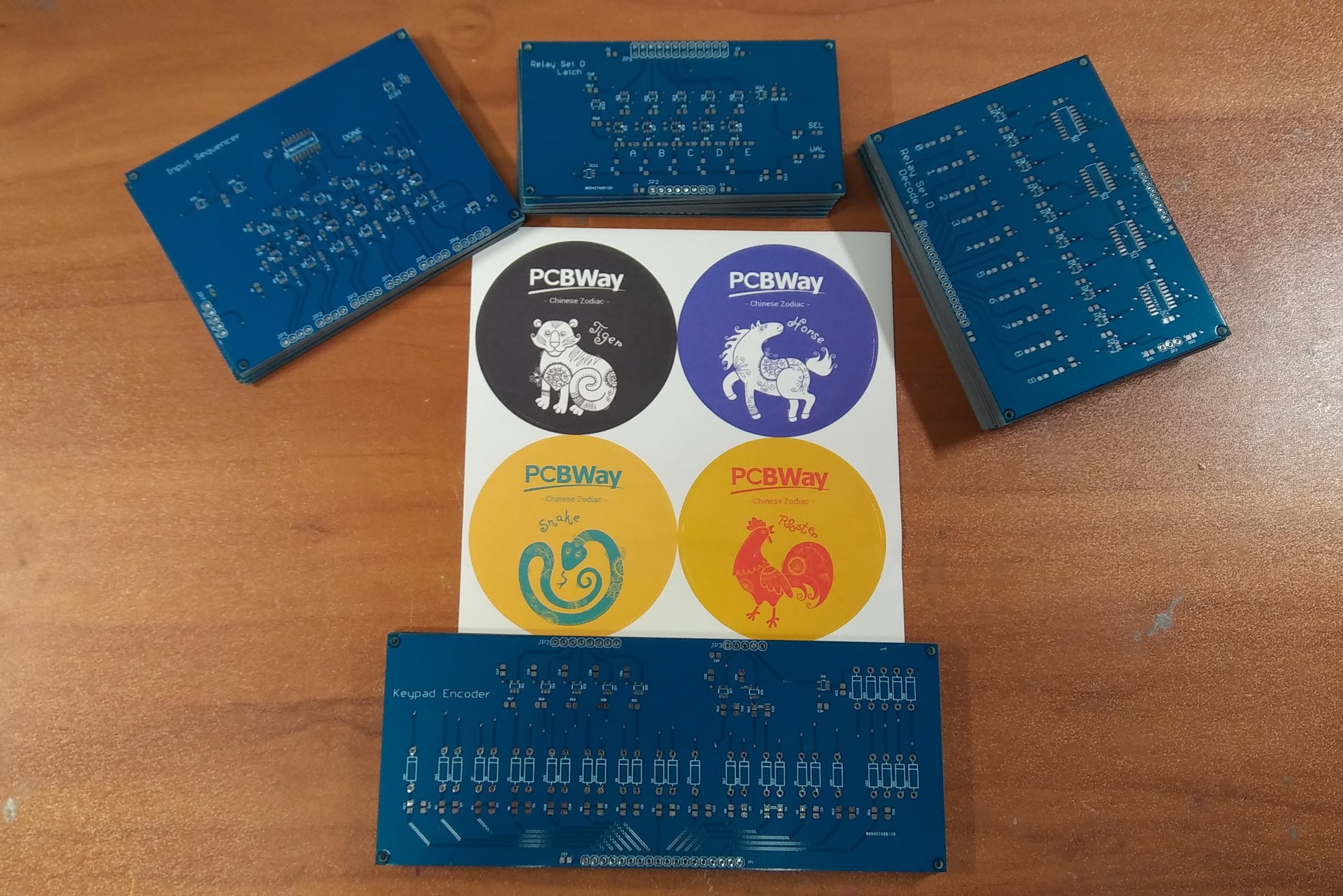
The new PCBs for the keypad encoder, input sequence generator, relay-d latch, and relay-d decoder arrived this afternoon. It is always a bit exciting to receive a new batch of PCBs. No matter how trivial the boards are, opening up the box with a little voice saying in your mind "I MADE THIS!". I mostly use PCBWay for prototype PCBs, and they often throw in something interesting with shipments. sometimes a pen or post-it notes. This time it was some Chinese Zodiac stickers! Looks like I have some work do this weekend assembling some boards!
-
Your Wiring is Mess
10/12/2017 at 18:29 • 0 comments![]()
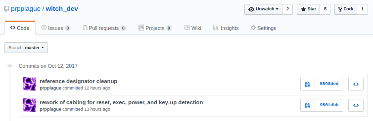
So after my integration testing ( You WILL be integrated! ), I realized that the routing of the cables and signals between the boards wasn't very optimal. I had already come to conclusion that I needed new PCBs to fix a bunch of small design issues, so I decided to overhaul the connections. I spent an entire evening making some mockups and routing cables to figure out the best way to connect everything, then updated all the design files, and ordered new PCBs. They should be in later next week! Fun Fun Fun!
-
You WILL be integrated!
09/23/2017 at 21:25 • 0 comments![]()
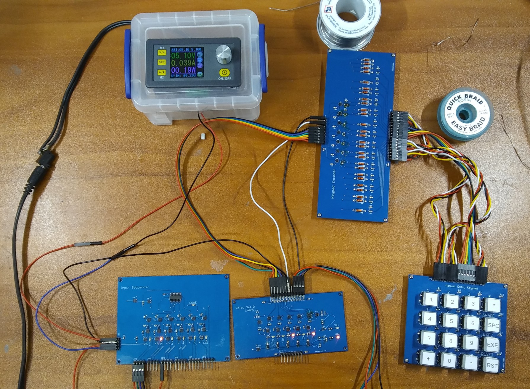
Well... after a few "blue wire fixes", I was able to test the Input Sequencer, Relay Set D Latch, Keyboard Encoder and the Manual Entry Keypad boards together! As noted in an earlier post ( One Down - Four to Go... Sorta ), I decided to only build up one of the Relay Set D Latch boards and I am glad I did! There were a couple minor mistakes on the board that I corrected with some blue wire. Now the question is: Do I Blue-Wire-Fix the rest of the boards, or do I correct the PCB and order new ones? Decisions... Decisions...
Either way, despite the futile attempts at resistance, I have integrated them!
-
Let Me Encode Your Keys!
09/23/2017 at 00:57 • 0 comments![]()
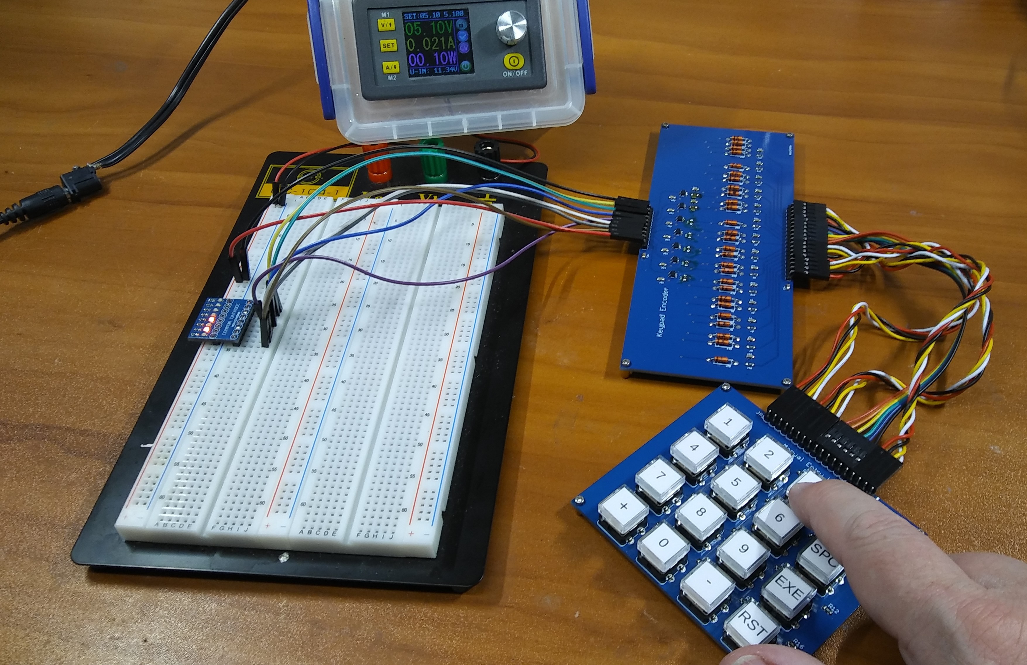
In my quest to get the input system working, I wired up the keypad and 5-bit baudot encoder to do some testing. I have it bread boarded with a little LED board I created to help with bread board testing that I call Dave's Breadboard Led Trinkit (BLT for short!). The encoding is not standard Binary Coded Decimal(BCD), but a variation of the 5-bit baudot code popular at the time the WITCH was built. I really could have made the diode steering board a lot smaller, but as I noted in another log post ( Keypad Encoder ), I had a bunch of vintage diodes that I thought might look cool to use...
-
One Down - Four to Go... Sorta
09/22/2017 at 22:12 • 0 comments![]()
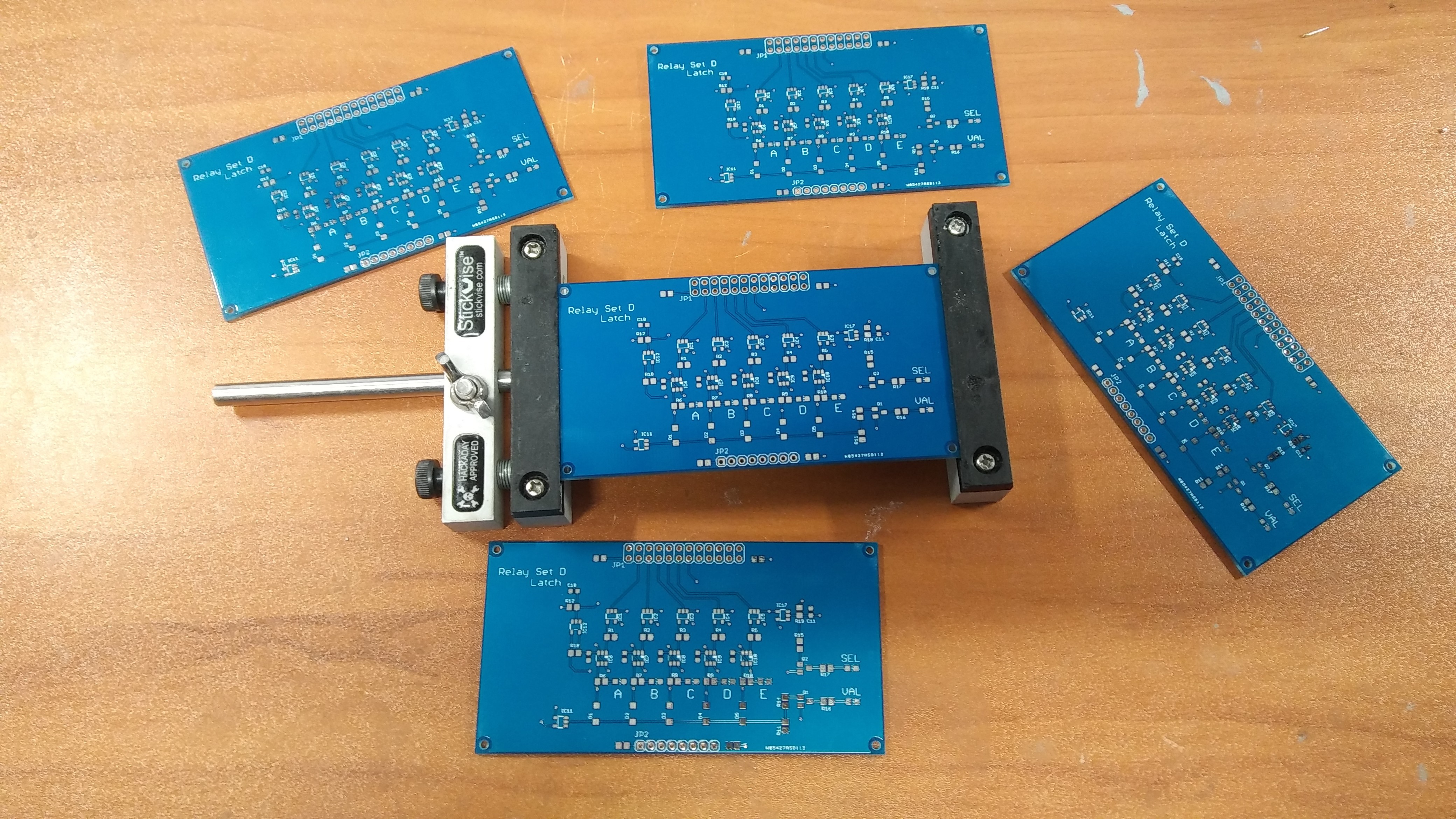
As I noted in my earlier log post ( Something to Latch Onto! ), I need to assemble 5 of these Relay Set D Latch boards to do my full test of the input system. I took an hour this afternoon to assemble one and I started thinking... this is a lot of assembly, I better make sure these work before I assemble four more! So I have one completely assembled and ready to test. I'll go through and get as much tested as possible before building up the other four!
-
Something to Latch Onto!
09/22/2017 at 19:48 • 0 comments![]()
In the original WITCH, the input system uses 5 module blocks know as "Relay Set D". Each Relay Set D, consists of two basic sections. One section is used to latch and "store" a 5-bit baudot code, and a second section to decode the 5-bit baudot code into a "1 of 10" decimal signal. For the WITCH-E design, I've broken the Latch and a Decode sections of the Relay Set D into separate PCBs. For me to test the keypad, keypad encoder, and input sequencer, I need to have 5 of the Latch PCBs assembled and tested. Looks like I have my work cut out for me this weekend....
-
New Input Sequencer Assembled
09/22/2017 at 03:50 • 0 comments![]()
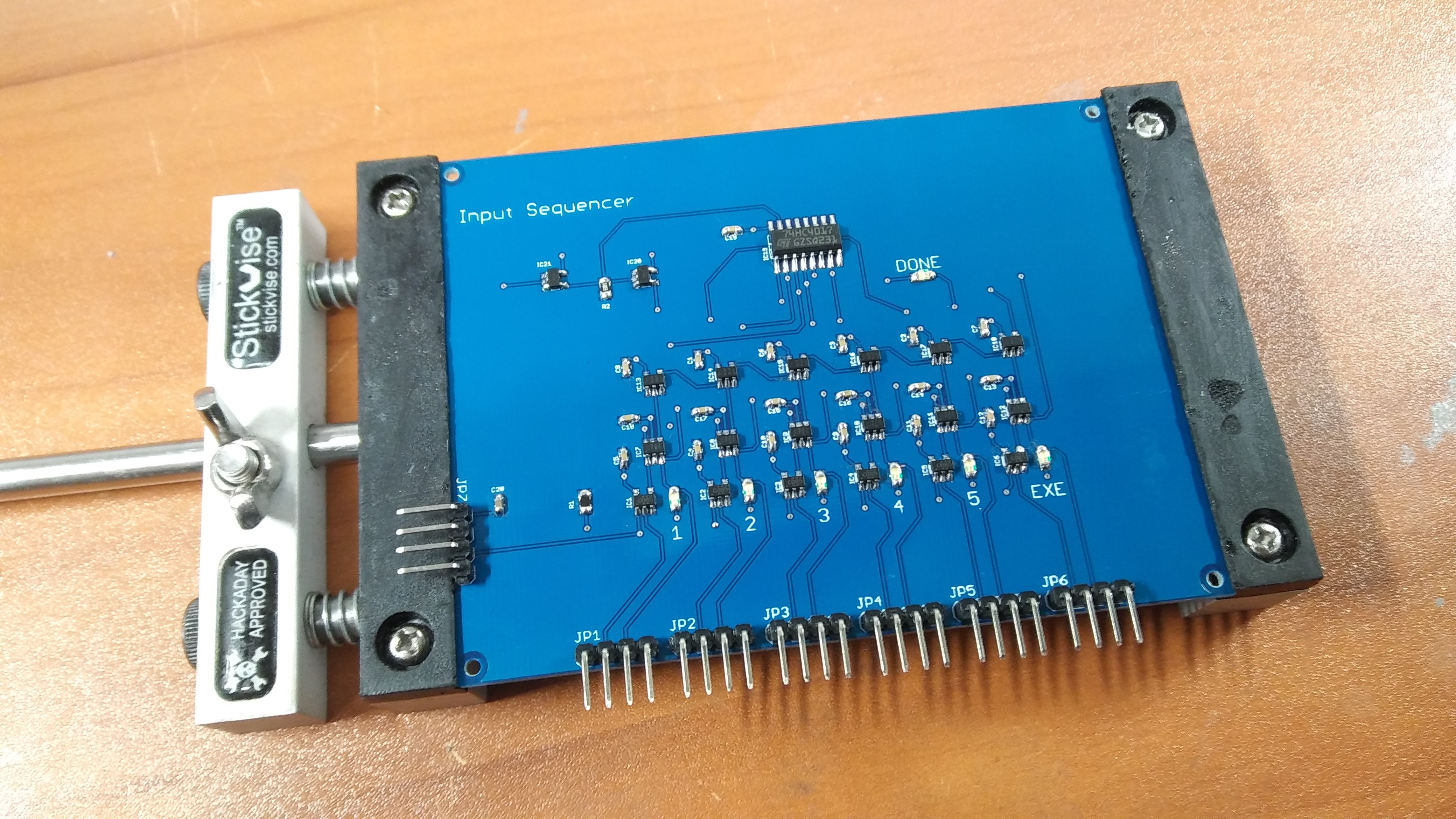
As noted in my earlier log post ( All Your Sequence Belong to Us! ), I had ordered and received some new Input Sequencer PCBs. After making that log post, I realized I didn't have enough parts to assemble the board, so I had to order some in from Digikey. The parts arrived this morning. I found some time this evening to do the assembly and get it ready for testing...
-
Steampunk Dekatron
09/21/2017 at 00:46 • 1 comment![]()
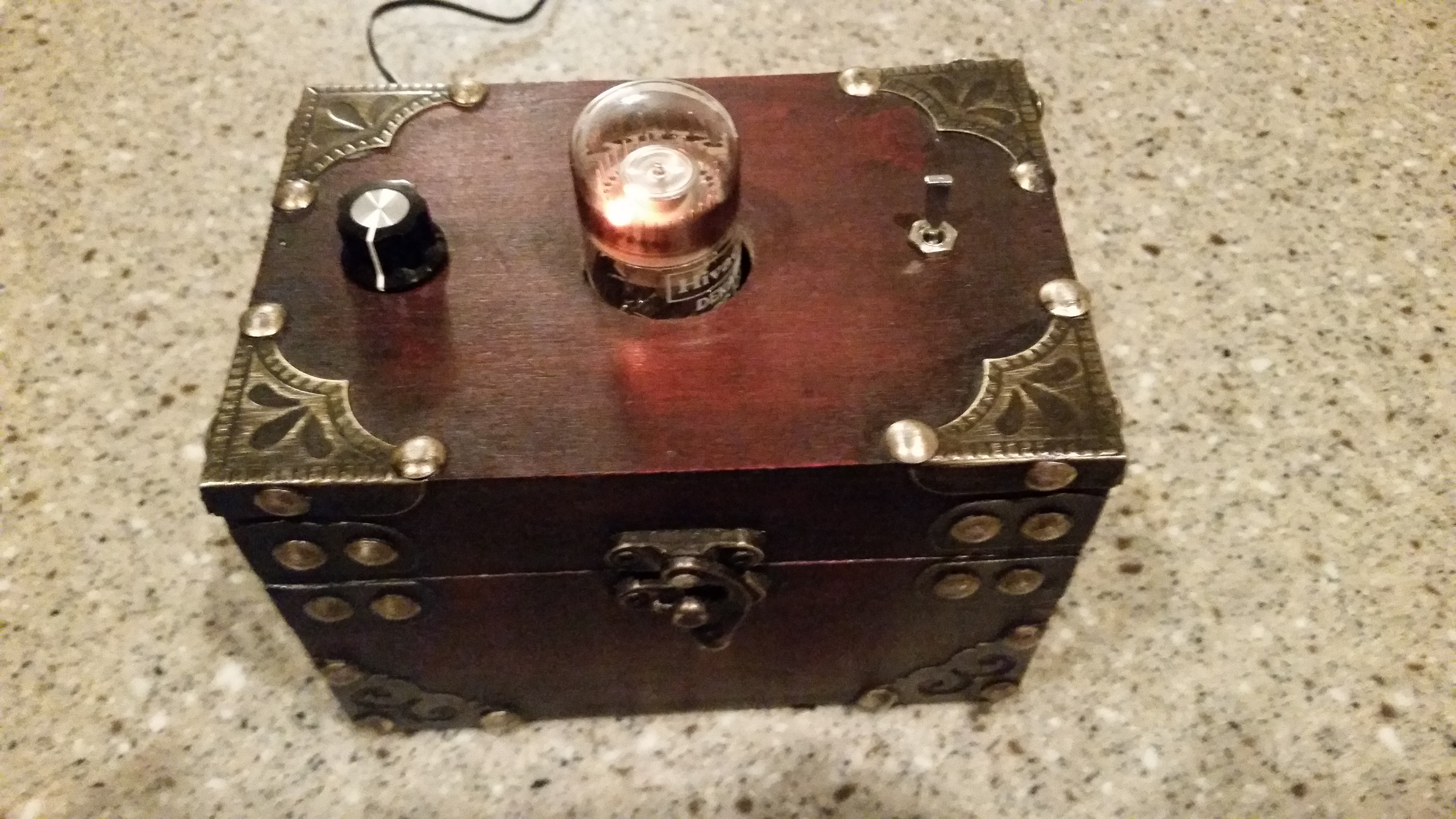
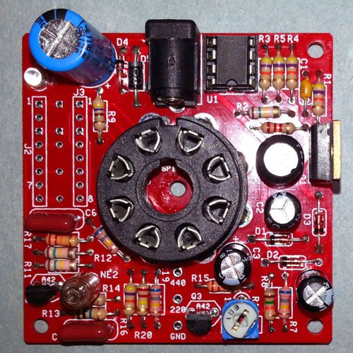
As I noted in another log post, my young friend Justin King worked on creating a javascript based WITCH emulator over the summer a few years ago. As a thank you for the work on the project, I wanted to give Justin a real Dekatron. I had previously found this Dekatron Spinner Kit on the net, and found the kit for sale on ebay, so I purchased an original GC10B Dekatron and a spinner kit. The kit is well designed and came with all the components ready for assembly. After assembly and testing, I thought to myself "Hey, this would look really cool in some sort of case!". After a little shopping at the local home decor store, I found this sweet little steampunk looking box. After drilling a hole for the Dekatron to extend through, I added a power switch and a potentiometer to adjust the speed of the spinner. I think it turned out pretty well, and Justin was very excited to receive it as a gift!
![]()
WITCH-E Decimal Based Computer
Document and create a modern replica of the Harwell Dekatron computer known as the WITCH