 kutluhan_aktar
-
1Design process, available features, and final results
As my projects became more intricate due to complex part designs, multiple development board integrations, and various features requiring interconnected networking, I decided to prepare more straightforward written tutorials with brevity and produce more comprehensive demonstration videos showcasing my entire design process, results, and device features from start to finish.
Thus, I highly recommend watching the project demonstration videos below to inspect my design process, the construction of the synthetic data set, and all of the shipping workstation features.
-
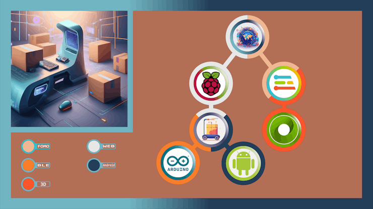
2Step 0: A simplified illustration of interconnected networking
As a part of preparing a more visually-inclined tutorial, I decided to create a concise illustration of interconnected networking infrastructure to delineate the complicated data transfer procedures between different development boards, complementary web, and mobile applications.
![]()
-
3Step 1: Testing electronic components and prototyping the device structure
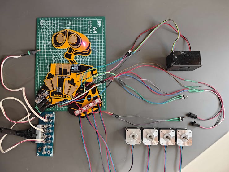
Before proceeding with designing 3D parts, I needed to determine all electrical components required to operate the real-world shipping workstation. Thus, I started to test and prepare electronic components for prototyping the device structure.
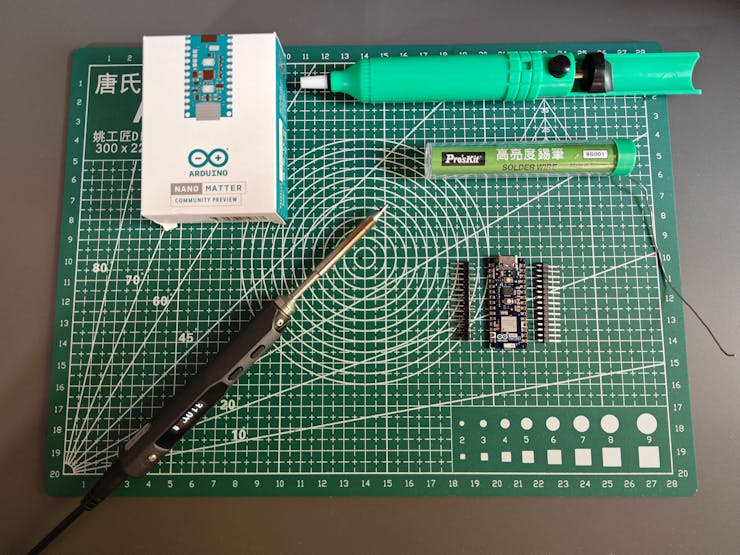
#️⃣ Since Arduino Nano Matter is a versatile IoT development board providing state-of-the-art Matter® and Bluetooth® Low Energy (BLE) connectivity thanks to the MGM240SD22VNA wireless module from Silicon Labs, I decided to base the shipping workstation control panel on Nano Matter.
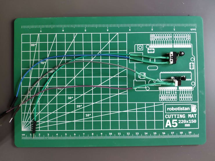
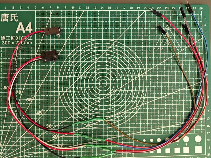
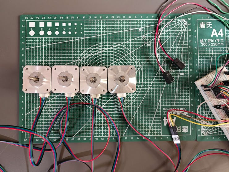
#️⃣ Since I envisioned a fully automated homing sequence for the moving workstation parts, I decided to utilize an IR break-beam sensor (300 mm) and two micro switches (KW10-Z5P).
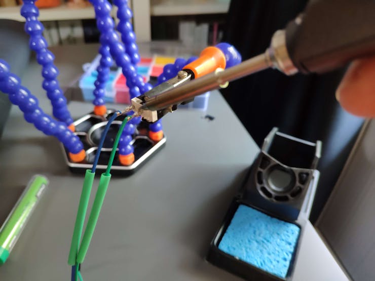
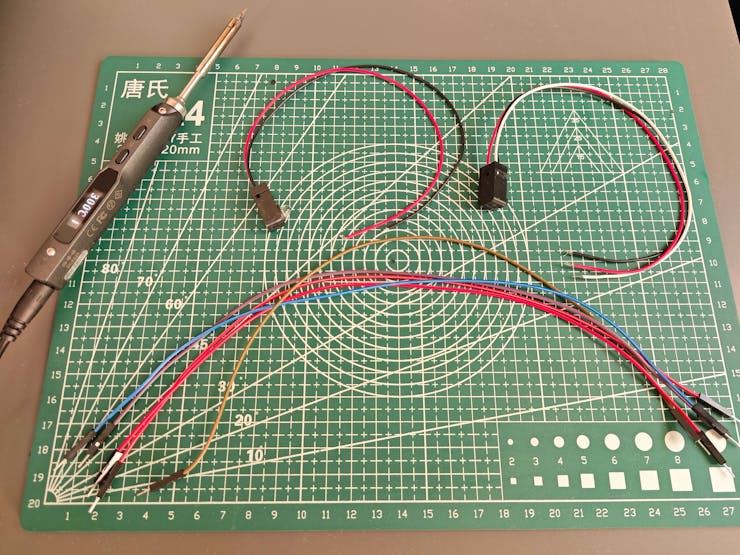
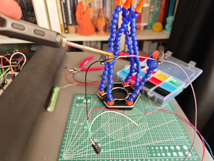
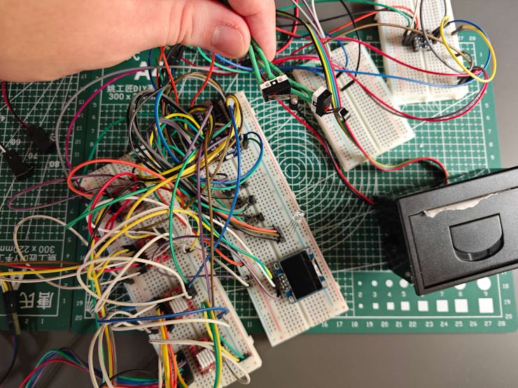
#️⃣ By utilizing a soldering station for tricky wire connections, I prepared the mentioned components for prototyping.
![]()
![]()
![]()
![]()
![]()
![]()
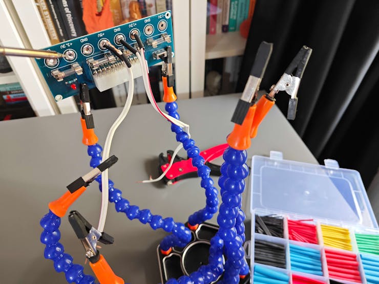
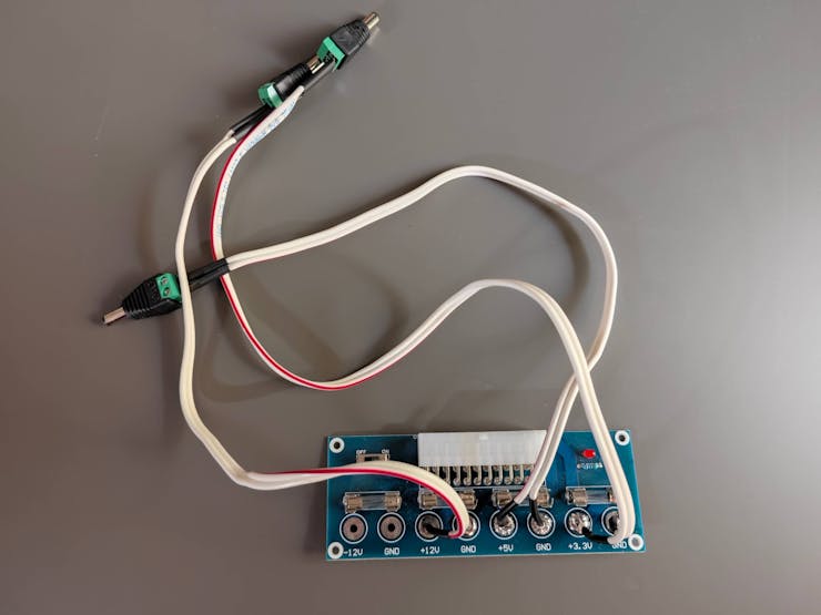
#️⃣ Since I needed to supply a lot of current-demanding electronic components with different operating voltages, I decided to convert my old ATX power supply unit (PSU) to a simple bench power supply by utilizing an ATX adapter board (XH-M229) providing stable 3.3V, 5V, and 12V. For each power output of the adapter board, I soldered wires via the soldering station to attach a DC-barrel-to-wire-jack (male) in order to create a production-ready bench power supply.
![]()
![]()
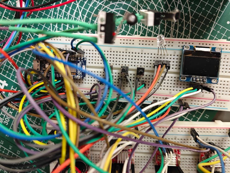
#️⃣ Since Nano Matter operates at 3.3V and the IR break-beam sensor requires 5V logic level voltage to generate powerful enough signals for motion detection, the sensor cannot be connected directly to Nano Matter. Therefore, I utilized a bi-directional logic level converter to shift the voltage for the connections between the IR sensor and Nano Matter.
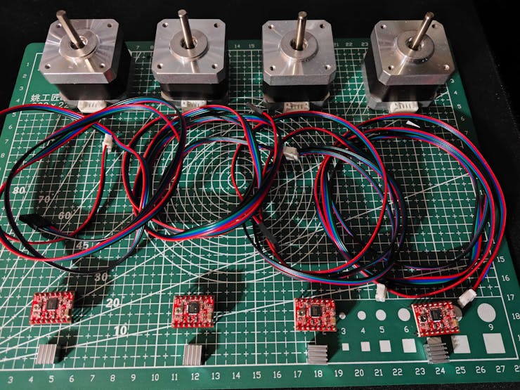
#️⃣ Since I planned to design intricate gear mechanisms to control the moving parts of the real-world shipping workstation, I decided to utilize four efficient and powerful Nema 17 (17HS3401) stepper motors, similar to most FDM 3D printers. To connect the Nema 17 stepper motors to Nano Matter securely, I employed four A4988 driver modules.
#️⃣ As a practical shipping workstation feature, I decided to connect a tiny (embedded) thermal printer to Nano Matter to print a shipping receipt for each completed order. I utilized a sticker paper roll to make receipts fastenable to cardboard boxes.
#️⃣ To build a feature-packed and interactive workstation control panel, I also connected an SSD1306 OLED display, three control buttons, and an RGB LED to Nano Matter.
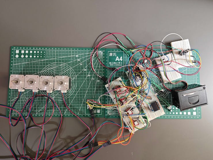
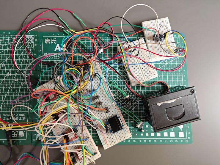
#️⃣ As depicted below, I made all component connections according to available and compatible Arduino Nano Matter pins.
// Connections
// Arduino Nano Matter :
//                                Nema 17 (17HS3401) Stepper Motor w/ A4988 Driver Module [Motor 1]
// 3.3V    ------------------------ VDD
// GND     ------------------------ GND
// D2      ------------------------ DIR
// D3      ------------------------ STEP
//                                Nema 17 (17HS3401) Stepper Motor w/ A4988 Driver Module [Motor 2]
// 3.3V    ------------------------ VDD
// GND     ------------------------ GND
// D4      ------------------------ DIR
// D5      ------------------------ STEP
//                                Nema 17 (17HS3401) Stepper Motor w/ A4988 Driver Module [Motor 3]
// 3.3V    ------------------------ VDD
// GND     ------------------------ GND
// D6      ------------------------ DIR
// D7      ------------------------ STEP
//                                Nema 17 (17HS3401) Stepper Motor w/ A4988 Driver Module [Motor 4]
// 3.3V    ------------------------ VDD
// GND     ------------------------ GND
// D8      ------------------------ DIR
// D9      ------------------------ STEP
//                                Tiny (Embedded) Thermal Printer
// D0/TX1  ------------------------ RX
// D1/RX1  ------------------------ TX
// GND     ------------------------ GND
//                                SSD1306 OLED Display (128x64)
// A4/SDA  ------------------------ SDA
// A5/SCL  ------------------------ SCL
//                                Infrared (IR) Break-beam Sensor [Receiver]
// A6      ------------------------ Signal
//                                Control Button (A)
// A0      ------------------------ +
//                                Control Button (B)
// A1      ------------------------ +
//                                Control Button (C)
// A2      ------------------------ +
//                                Micro Switch with Pulley [First]
// A3      ------------------------ +
//                                Micro Switch with Pulley [Second]
// A7      ------------------------ +
//                                5mm Common Anode RGB LED
// D10     ------------------------ R
// D11     ------------------------ G
// D12     ------------------------ B
![]()
![]()
![]()
![]()
![]()
![]()
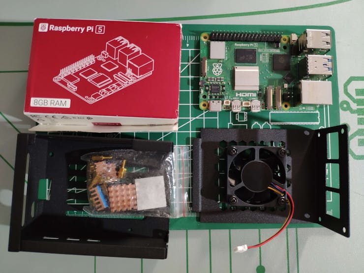
#️⃣ Furthermore, I put Raspberry Pi 5 into its aluminum case providing a cooling fan to secure all cable connections.
![]()
-
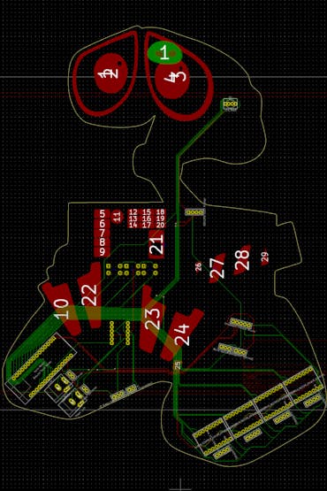
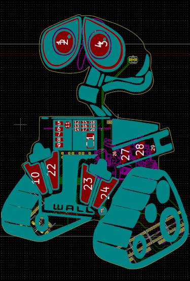
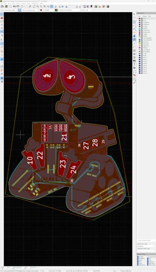
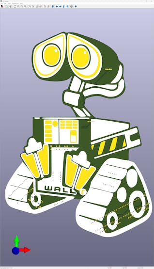
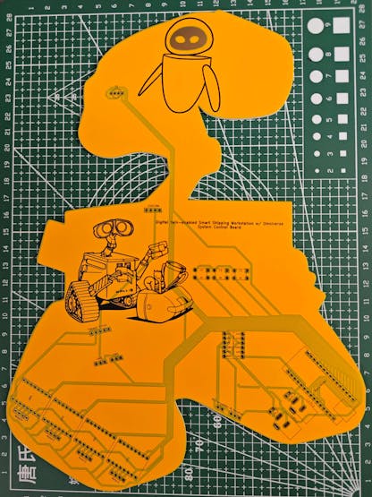
4Step 1.1: Designing the Wall-E-inspired PCB layout and silkscreen graphics
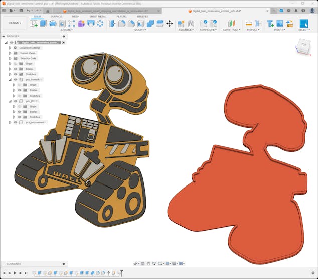
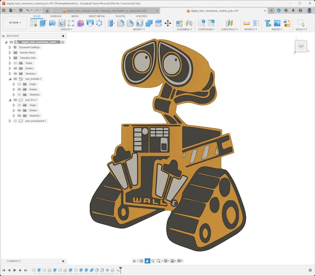
As I was prototyping the device structure and conceptualizing the workstation features, I pondered the question of how I should design a unique PCB for a smart shipping workstation. Then, I remembered the perennial efforts of Wall-E to move and arrange garbage as small packages. Thus, I drew my inspiration from Wall-E while designing this PCB, running an automated package-moving operation :)
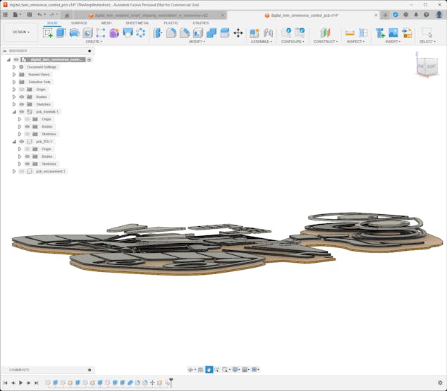
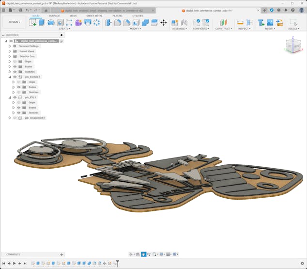
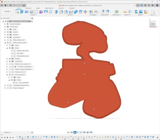
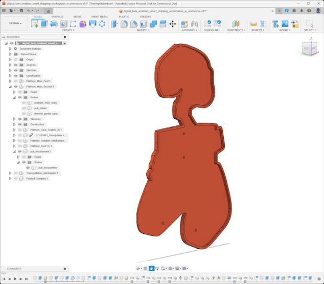
To simplify the PCB integration and place electronic components precisely while designing complementary 3D parts, I created the Wall-E PCB outline and a snug-fit PCB encasement on Autodesk Fusion 360.
![]()
![]()
![]()
![]()
![]()
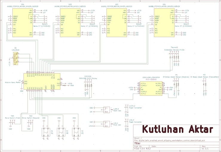
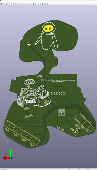
Then, I imported my outline graphic to Kicad 8.0 in the DXF format and designed the Wall-E PCB layout and silkscreen graphics according to the prototype electronic component connections.
![]()
![]()
![]()
![]()
![]()
![]()
-
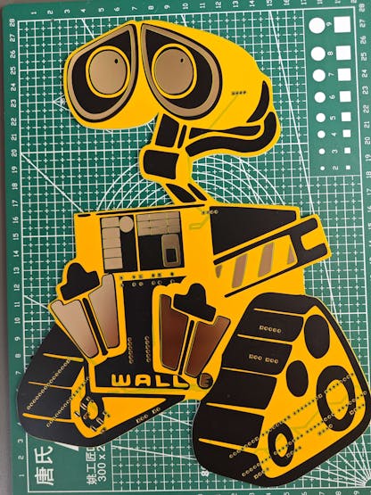
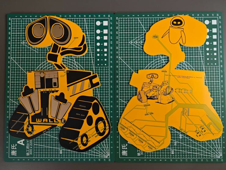
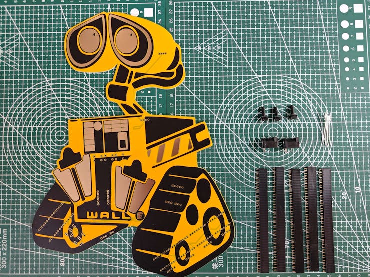
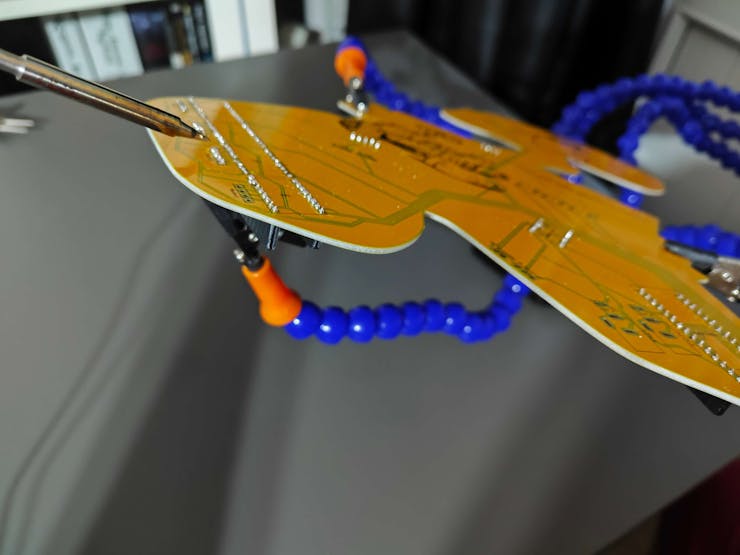
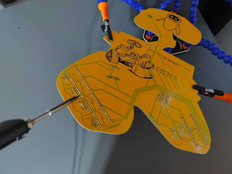
5Step 1.2: Soldering and assembling the Wall-E PCB
After completing the Wall-E PCB design, I utilized ELECROW's high-quality PCB manufacturing services. For further inspection, I provided the fabrication files of this PCB below, or you can order it directly from my ELECROW community page.
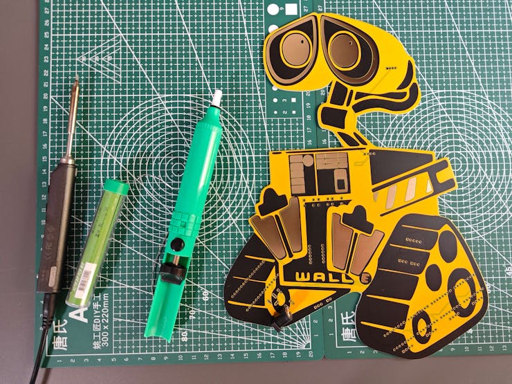
#️⃣ After receiving my PCBs, I attached all electronic components by utilizing a TS100 soldering iron and the soldering station.
📌 Component assignments on the Wall-E PCB:
A1 (Headers for Arduino Nano Matter)
DR1, DR2, DR3, DR4 (Headers for A4988 Stepper Motor Driver)
Motor1, Motor2, Motor3, Motor4, (Headers for Nema 17 [17HS3401] Stepper Motor)
SSD1306 (Headers for SSD1306 OLED Display)
Thermal1 (Headers for Embedded Thermal Printer)
L1 (Headers for Bi-Directional Logic Level Converter)
IR1 (IR Break-beam Sensor [Receiver])
IR2 (IR Break-beam Sensor [Transmitter])
SW1, SW2 (Micro Switch [KW10-Z5P])
C1, C2, C3 (6x6 Pushbutton)
D1 (5 mm Common Anode RGB LED)
J_5V_1, J_12V_1 (DC Barrel Female Power Jack)
J_5V_2, J_12V_2 (Headers for Power Supply)
![]()
![]()
![]()
![]()
![]()
![]()
![]()
![]()
![]()
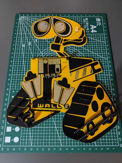
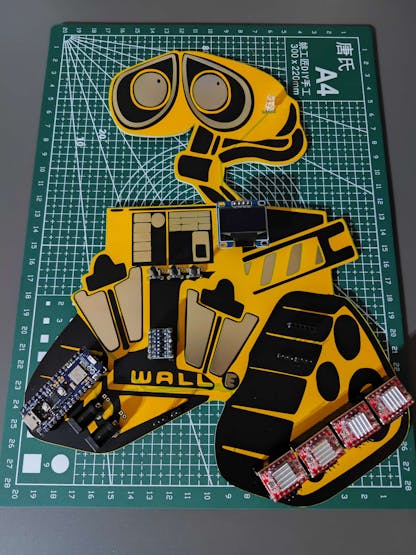
After concluding soldering components to the Wall-E PCB, I tested whether the PCB worked as expected or was susceptible to electrical issues; I did not encounter any problems.
![]()
![]()
-
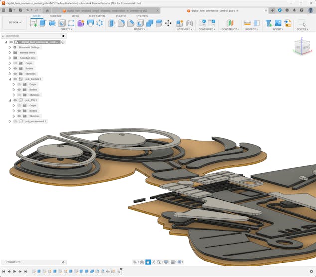
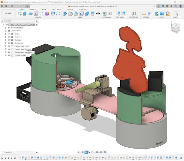
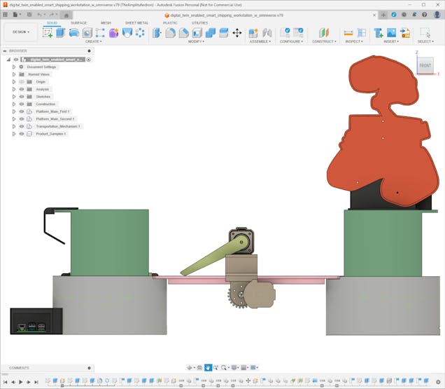
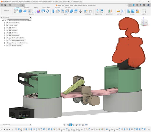
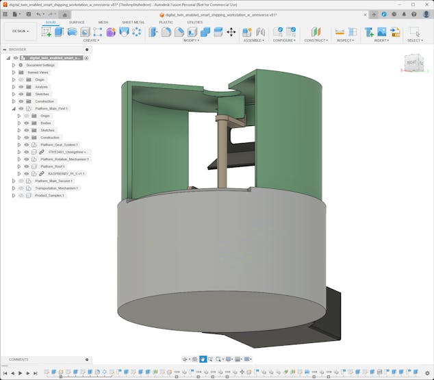
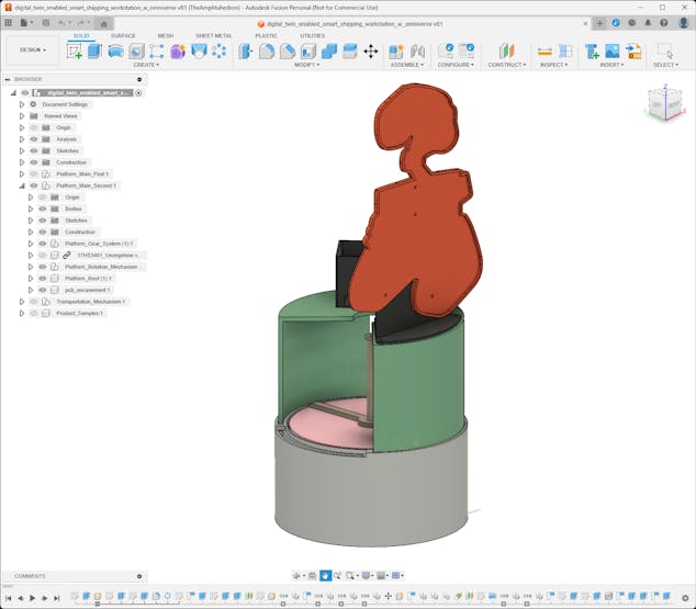
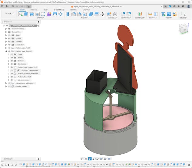
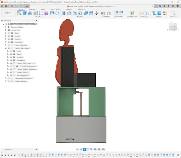
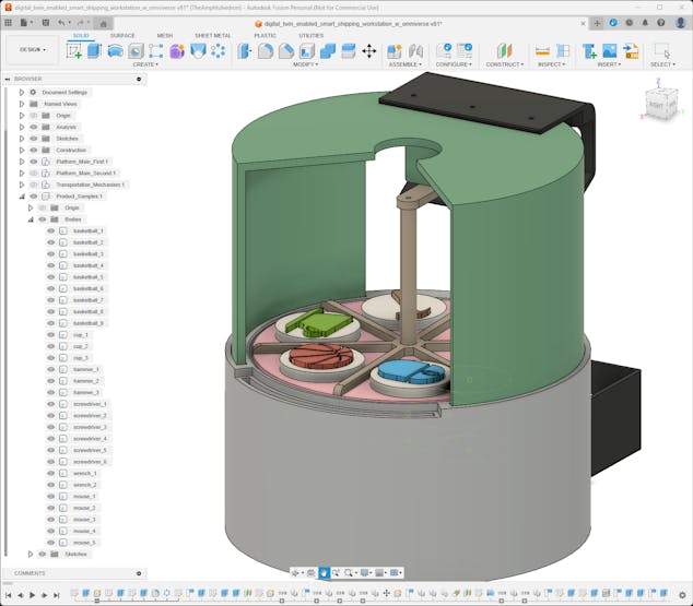
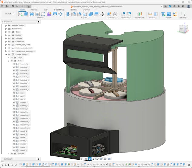
6Step 2: Creating a fully functional virtual shipping workstation
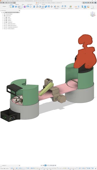
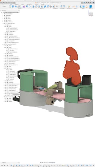
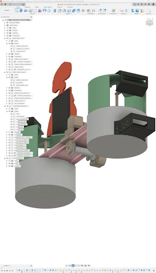
Even though I decided to build a virtual shipping workstation to present my reverse digital twin approach as a proof-of-concept project, I focused on designing an intricate mechanism manifesting an industrial-level shipping operation providing a professional product transportation system and a custom warehouse management system.
I designed all shipping workstation 3D parts on Autodesk Fusion 360, including custom mechanical parts for moving components.
While designing 3D parts, I utilized some third-party CAD files to obtain accurate measurements and create a precise virtual construction.
Nema 17 (17HS3401) Stepper Motor | Inspect
Raspberry Pi 5 | Inspect
In the following steps, I will explain my design process for each 3D part categorically.
After finalizing all 3D parts, I exported the virtual shipping workstation as a single file in the OBJ format to produce an accurate virtual representation of the shipping workstation.
![]()
![]()
![]()
![]()
![]()
![]()
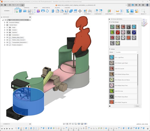
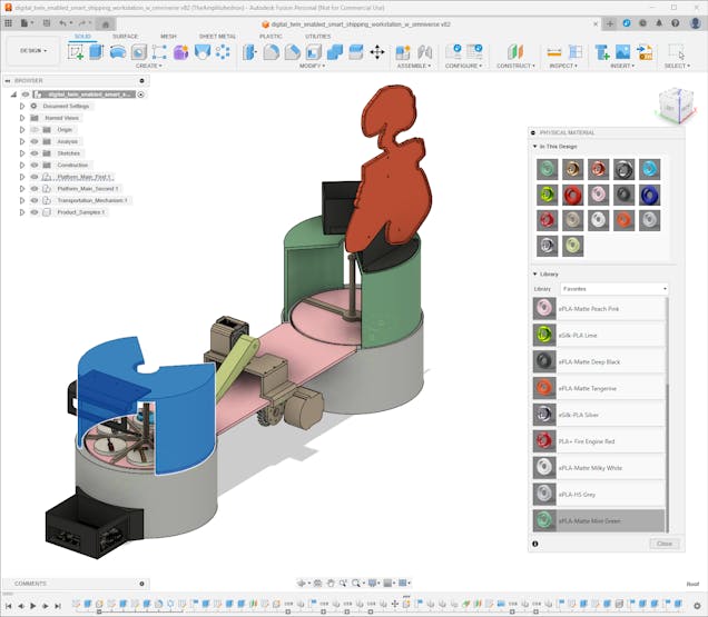
In accordance with my reverse digital twin approach, I had to envision each virtual shipping workstation 3D part appearance as close as possible to their real-world counterparts since I needed to construct a synthetic data set and train an object detection model even before printing these 3D parts. Therefore, while designing, I decided on the filaments I would utilize for each 3D part. Then, I searched for material type and color code for each filament to assign them to the corresponding 3D parts on Fusion 360.
I selected these PLA filaments for different 3D parts.
🎨 For shipping workstation 3D parts:
- ePLA-HS Grey (#B5B8BE)
- ePLA-Matte Mint Green (#6DA582)
- ePLA-Matte Peach Pink (#F9C0CF)
- ePLA-Matte Deep Black (#2F3231)
- ePLA-Matte Milky White (#F7F5F4)
- ePLA-Matte Light Khaki (#AD9E8D)
- ePLA-Matte Tangerine (#E24C13)
- ePLA-Matte Almond Yellow (#C7D58C)
🎨 For sample product 3D parts:
- eSilk-PLA Lime (#9CE40C)
- eSilk-PLA Silver (#AAA3B5)
- eSilk-PLA Jacinth (#FF8472)
- ePLA-Metal Antique Brass (#CB9E70)
- PLA+ Light Blue (#37B8F5)
- PLA+ Fire Engine Red (#A62E34)
![]()
![]()
-
7Step 2.1: Designing mechanical 3D components
Since I wanted to design the shipping workstation from the ground up, I decided to create custom mechanical components for the moving workstation parts.
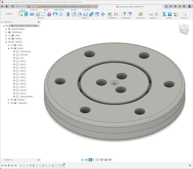
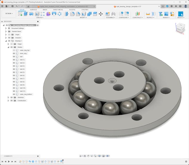
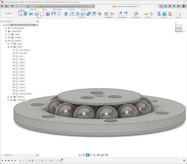
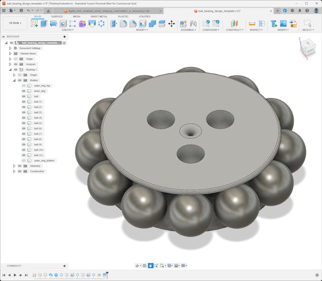
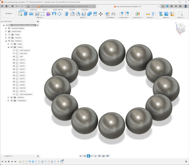
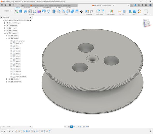
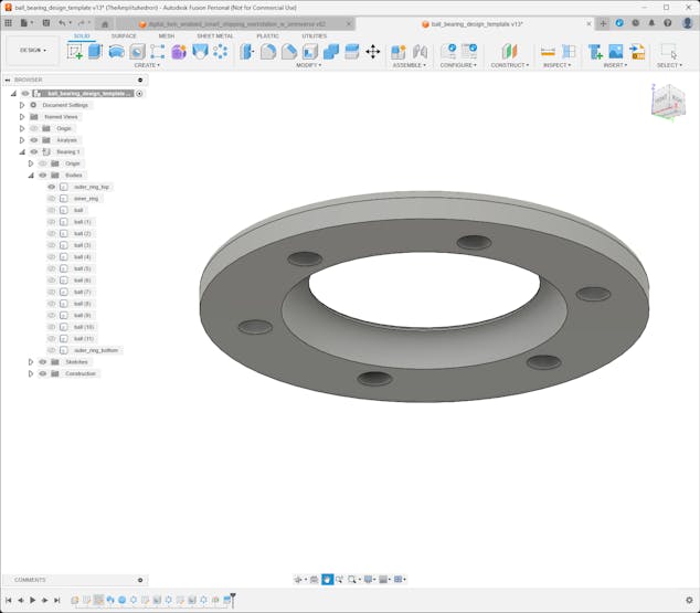
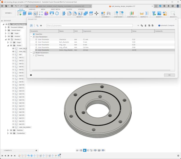
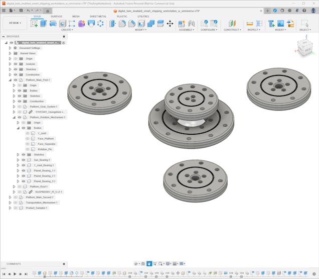
#️⃣ First, I started to work on designing a template for bearings optimized for 5 mm steel balls. In this regard, I was able to create ball bearings in different sizes to swivel mechanical components.
#️⃣ For a simple assembly process, I designed the bearing template in three parts: inner ring, top outer ring, and bottom outer ring. The outer ring (top and bottom) includes M3 screw holes to adjust the bearing tightness easily.
#️⃣ Since I used parameters to define the dimensions and clearances of the bearing template, I was able to create custom bearings in different sizes effortlessly.
![]()
![]()
![]()
![]()
![]()
![]()
![]()
![]()
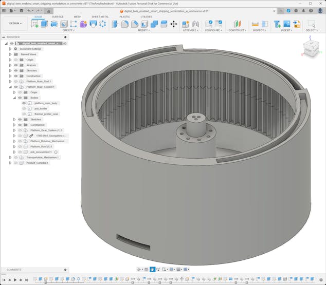
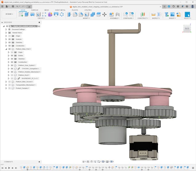
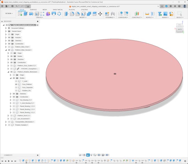
After completing the ball bearing template, I started to work on designing the two rotating platforms for storing and presenting sample products respectively.
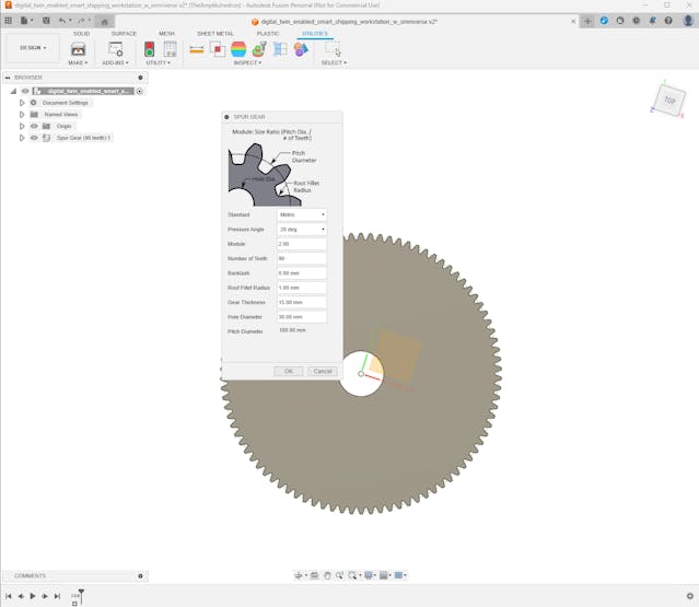
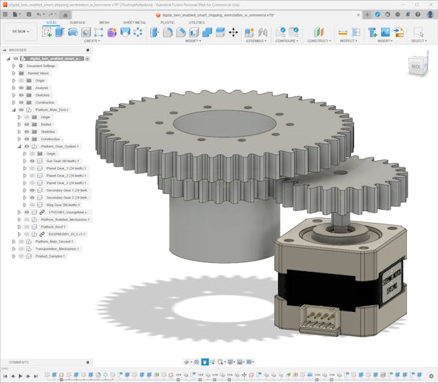
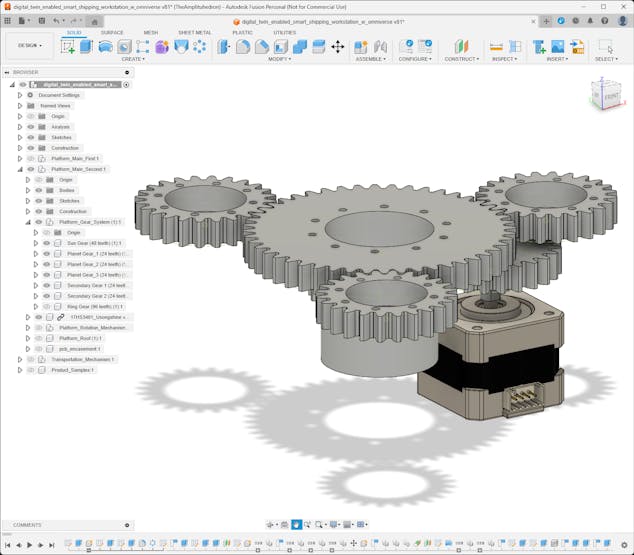
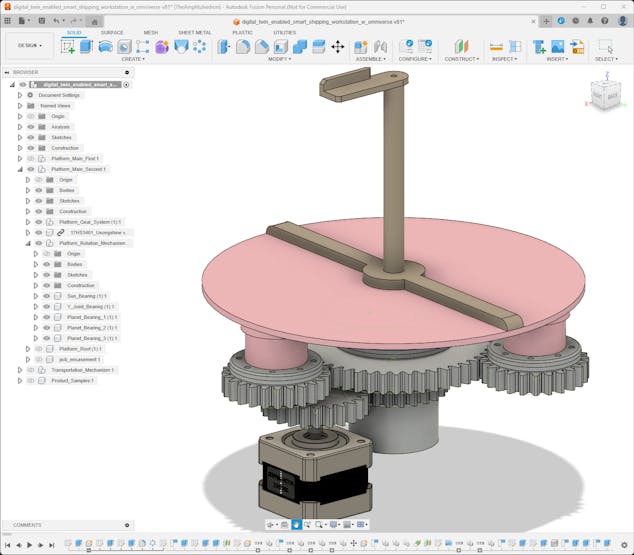
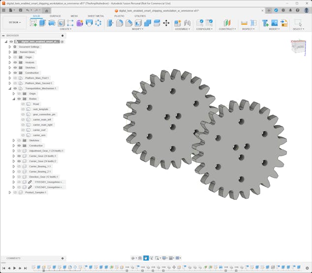
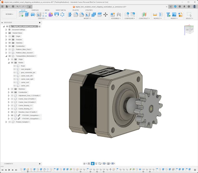
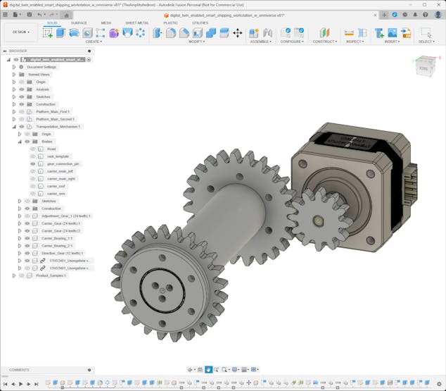
Since I wanted to create an industrial-level shipping workstation and showcase the digital twin capabilities for intricate mechanical components, I decided to design planetary gear mechanisms to rotate the platforms.
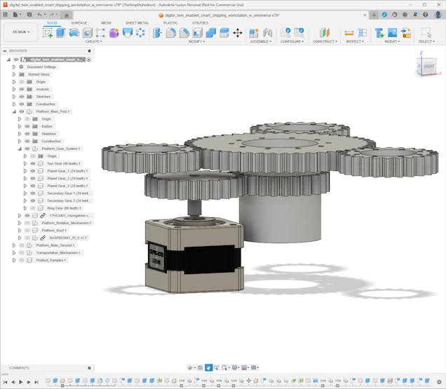
To generate gears in different sizes, I utilized the SpurGear add-in script.
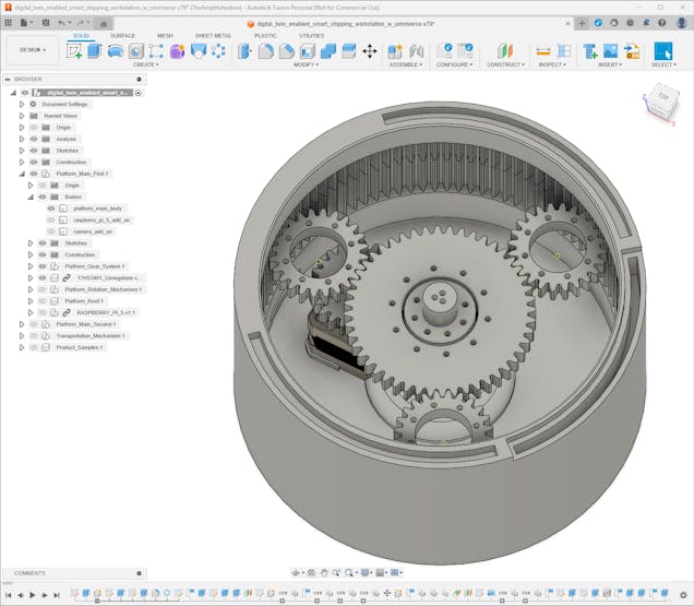
After experimenting with virtual planetary gear configurations, I decided to fix the ring gear and employ the planet carrier (Y-shaped) to attach and rotate the platform face. In this configuration, the sun gear behaves as the driver gear and provides higher torque while maintaining a lower speed.
To determine gear ratios and teeth numbers, I applied these equations:
🔢 Variables
- R ➡ Ring gear teeth number
- S ➡ Sun gear teeth number
- P ➡ Planet gear teeth number
- Tr ➡ Ring gear rotation
- Ts ➡ Sun gear rotation
- Ty ➡ Planet carrier (Y-shaped) rotation
🔢 Equations
- R = (2 × P) + S
- (R + S) × Ty = (R × Tr) + (Ts × S)
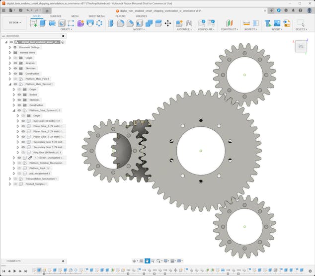
🔢 Since the ring gear is fixed and I wanted to have a 1/3 gear ratio for Ty/Ts:
- (R + S) × Ty = Ts × S
- Ty = Ts × (S / (R + S))
- R = 96
- S = 48
- P = 24
![]()
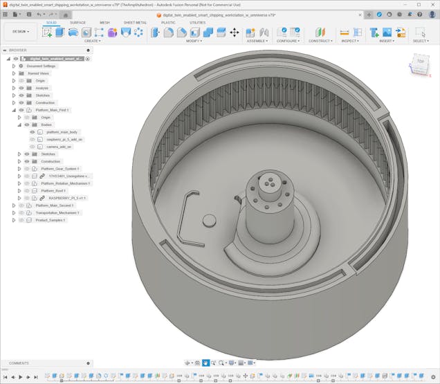
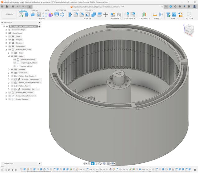
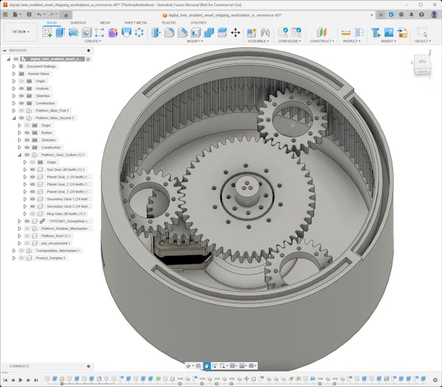
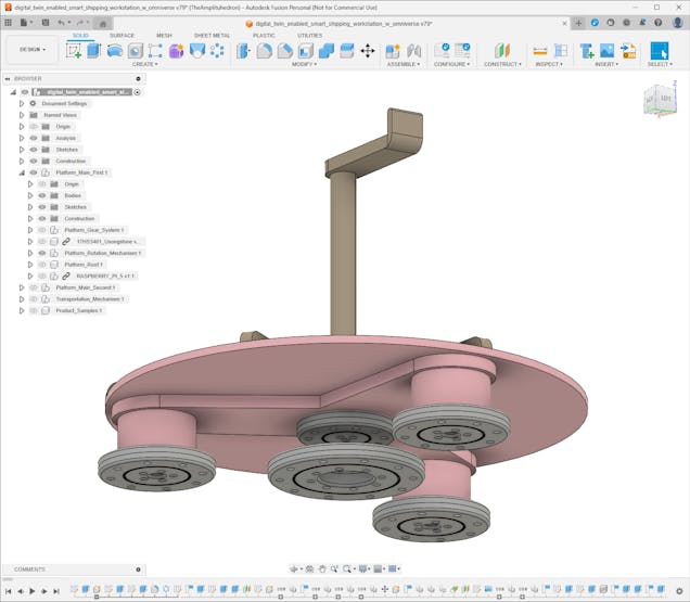
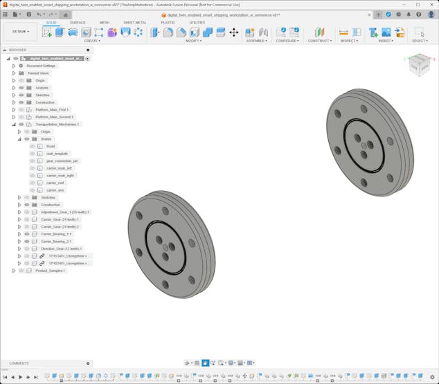
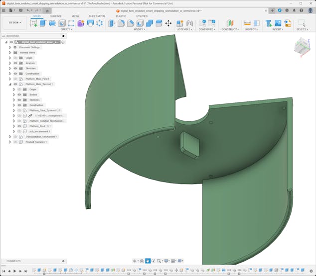
#️⃣ According to the fixed ring planetary gear configuration, I designed the platforms with the embedded ring gear.
⚙️ First platform:
![]()
![]()
![]()
![]()
⚙️ Second platform:
![]()
![]()
![]()
![]()
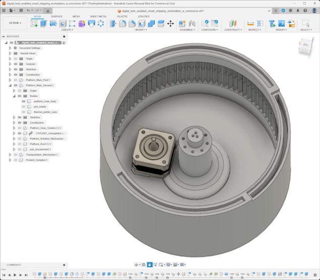
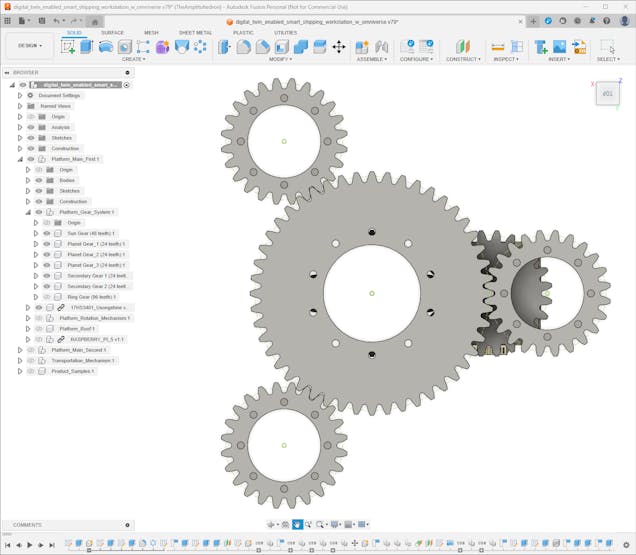
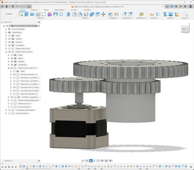
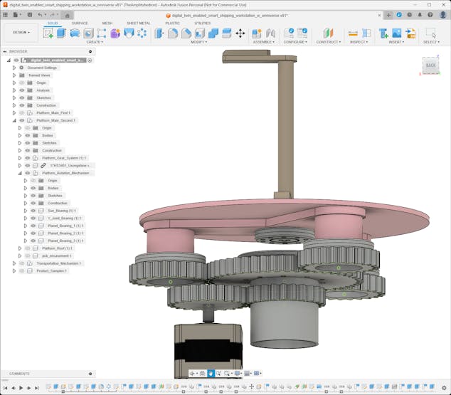
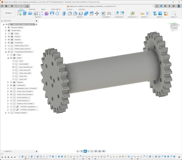
#️⃣ Then, I designed the planet gears, the sun gear, and the secondary stepper motor gear. In this regard, the Nema 17 stepper motor attached to the platform drives the secondary gear to rotate the sun gear which drives the planet gears.
⚙️ First platform:
![]()
![]()
![]()
![]()
![]()
⚙️ Second platform:
![]()
![]()
![]()
![]()
![]()
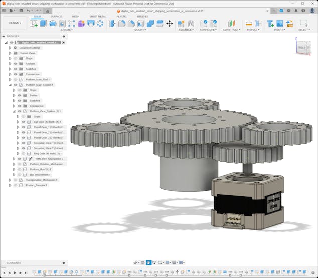
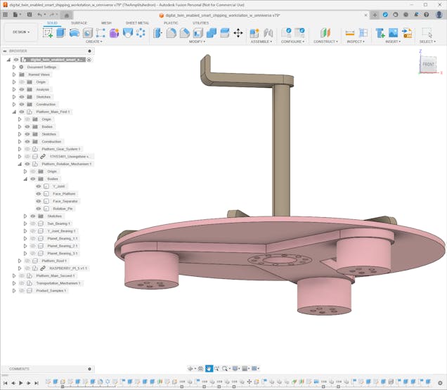
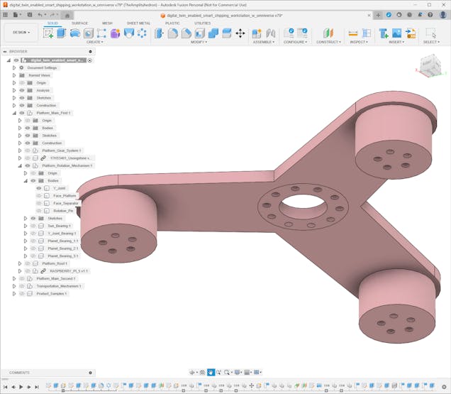
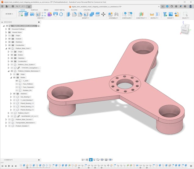
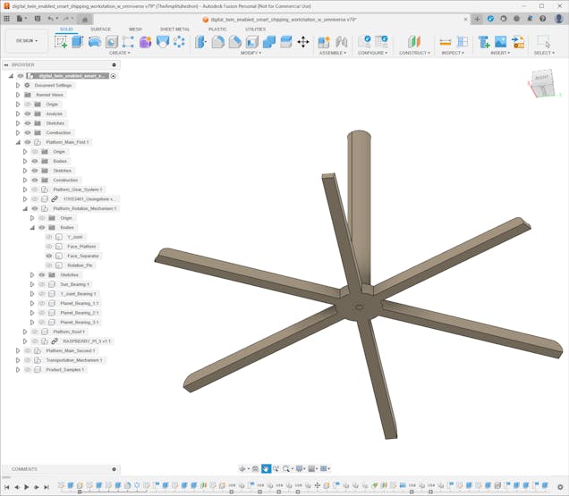
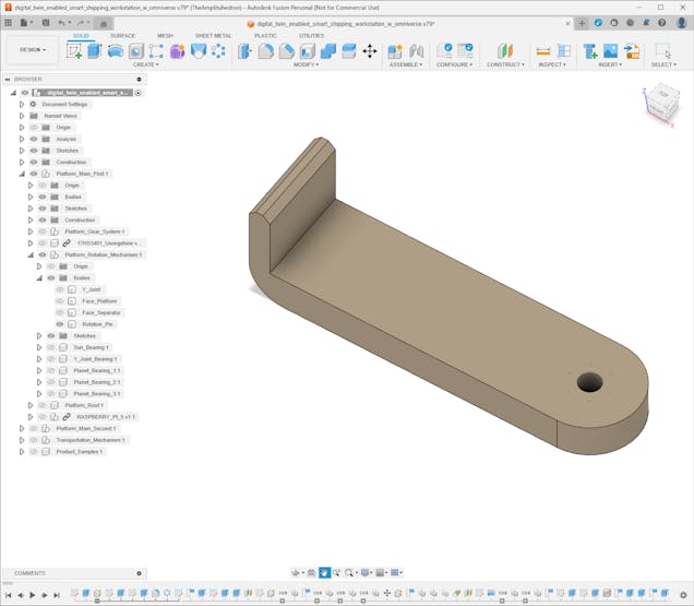
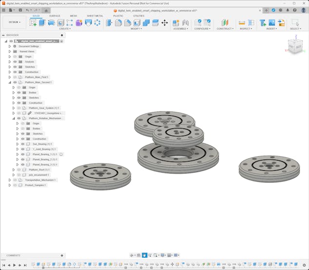
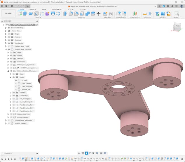
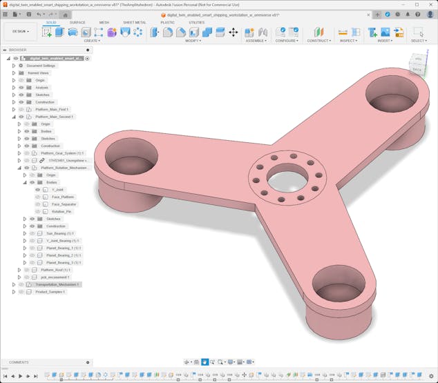
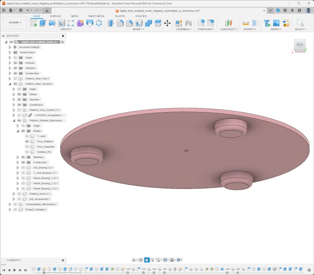
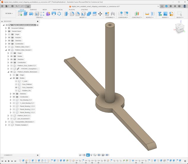
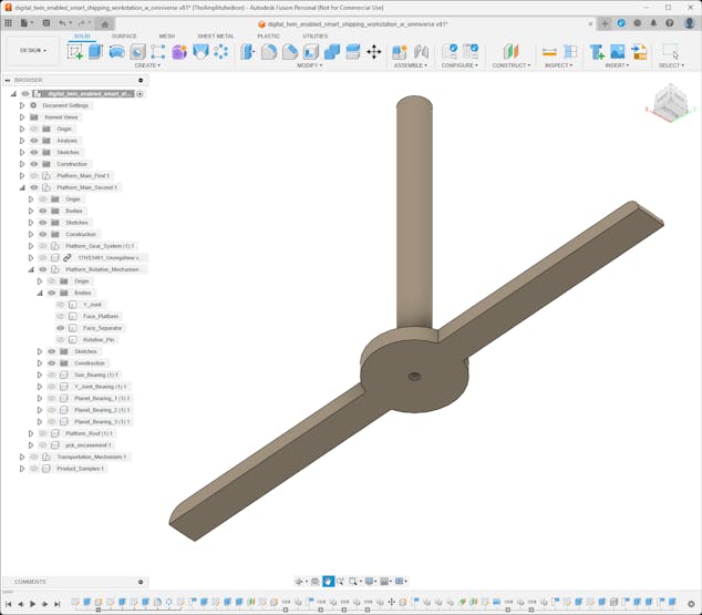
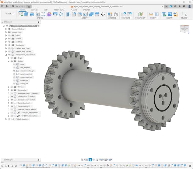
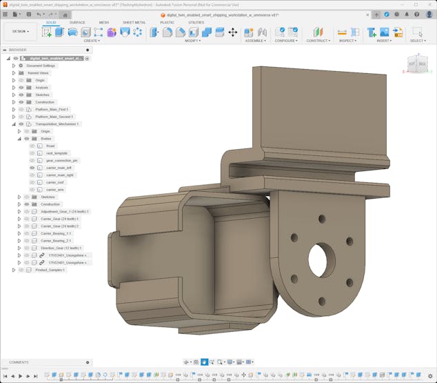
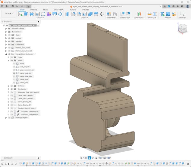
#️⃣ After completing the planetary gear mechanisms, I designed the Y-shaped planet carrier connected to the planet gears via custom bearings.
#️⃣ To stabilize torque distribution, the sun gear and the planet carrier are connected to the central shaft of the platform via custom bearings.
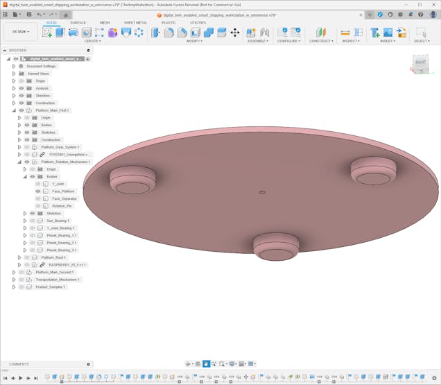
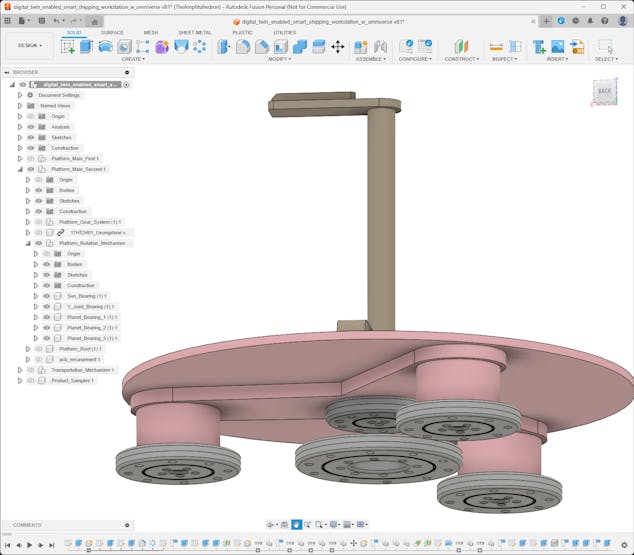
#️⃣ Then, I designed platform faces attached to the Y-shaped planet carriers via snap-fit joints.
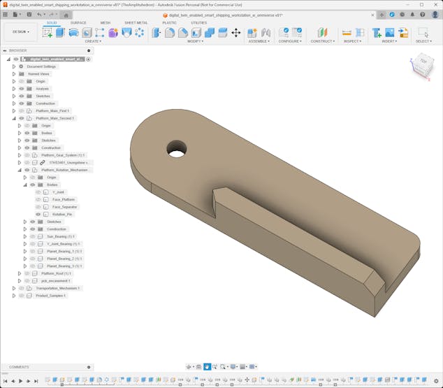
#️⃣ Since the first rotating platform stores sample products and the second rotating platform presents the transported product, I designed face separators and rotation pins accordingly.
#️⃣ The rotation pins are tailored for the selected platform homing methods — IR break-beam sensor and micro switch.
⚙️ First platform:
![]()
![]()
![]()
![]()
![]()
![]()
![]()
![]()
![]()
![]()
![]()
⚙️ Second platform:
![]()
![]()
![]()
![]()
![]()
![]()
![]()
![]()
![]()
![]()
![]()
-
8Step 2.2: Designing product transportation mechanism
After completing both rotating platform systems, I started to work on the industrial-level transportation mechanism to move the selected sample product from the first platform to the second platform.
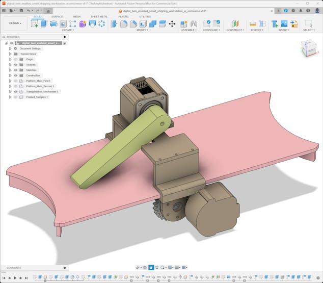
Conforming with my mechanical part design principle for the moving parts of the shipping workstation, I utilized gears to move the carrier on the transportation road. Nonetheless, since the product transportation mechanism requires linear motion, I designed a rack and pinion system converting rotational motion to linear motion.
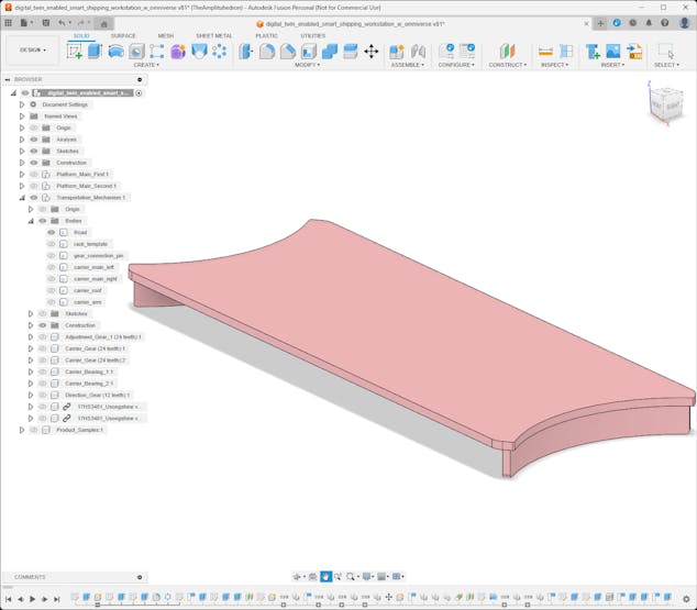
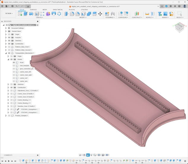
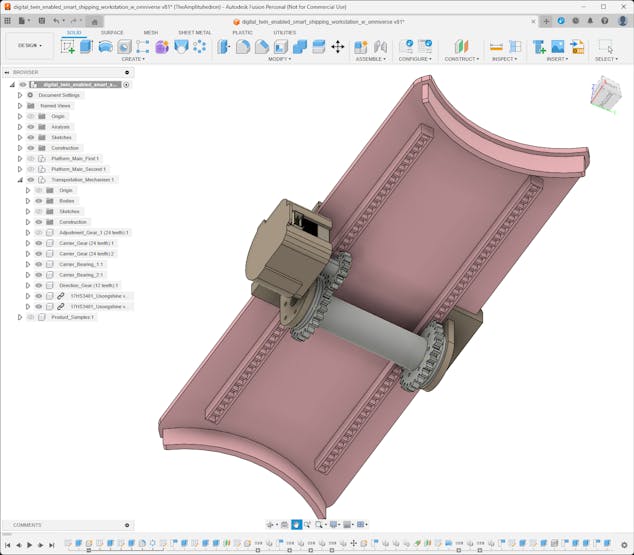
#️⃣ First, I designed the transportation road, bridging the first platform with the second platform. I integrated two linear gears (racks) at the bottom of the transportation road.
![]()
![]()
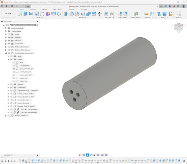
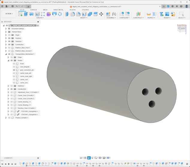
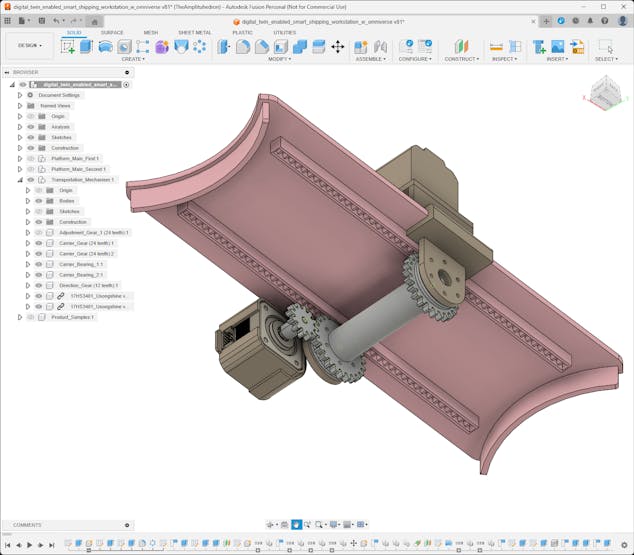
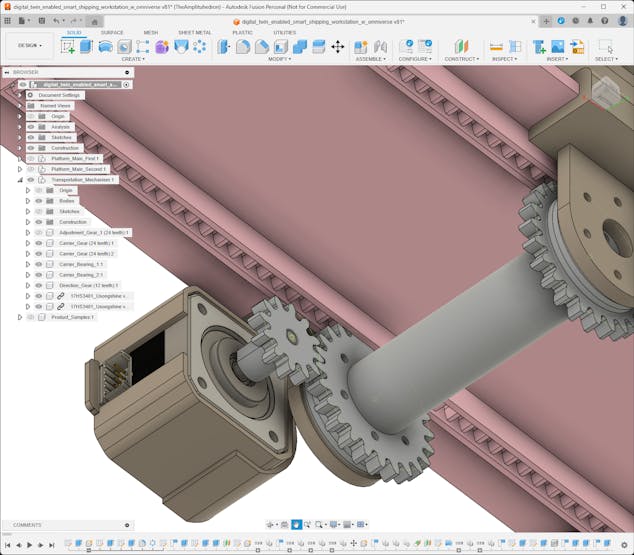
#️⃣ Then, I designed pinions, the pinion connection pin, and the stepper motor direction gear.
![]()
![]()
![]()
![]()
![]()
![]()
![]()
![]()
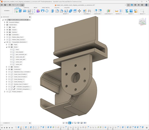
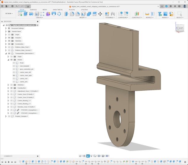
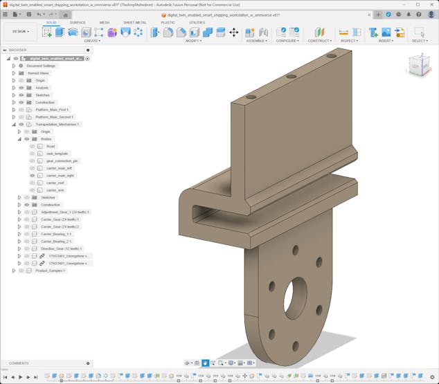
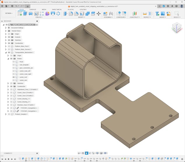
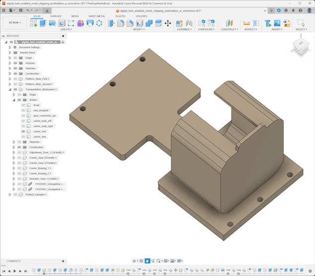
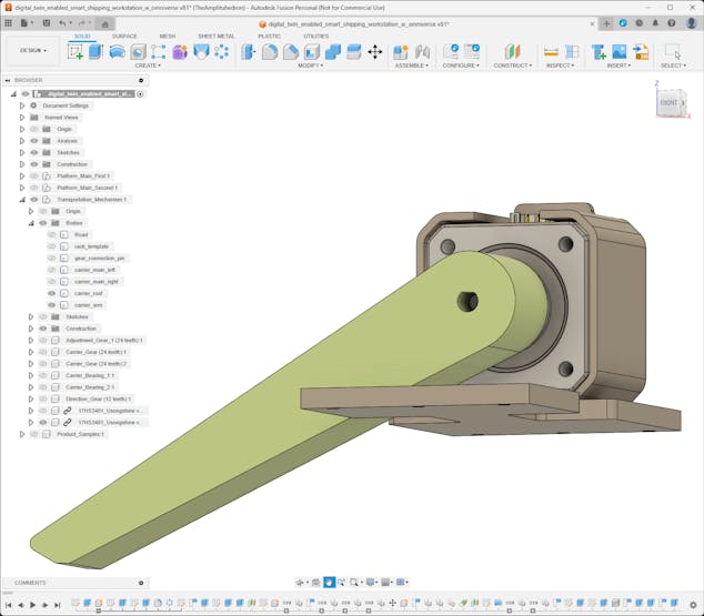
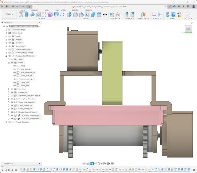
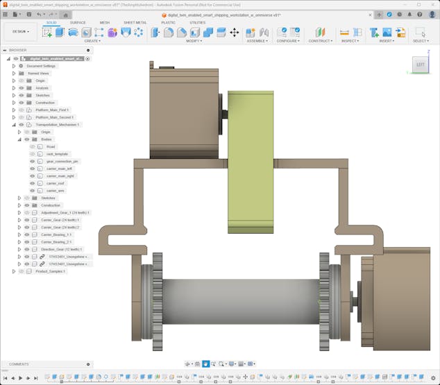
#️⃣ After completing the rack and pinion system, I designed the transportation carrier. I employed custom bearings to connect the carrier, pinions, and the pinion connection pin to enable linear motion while maintaining a stable torque distribution.
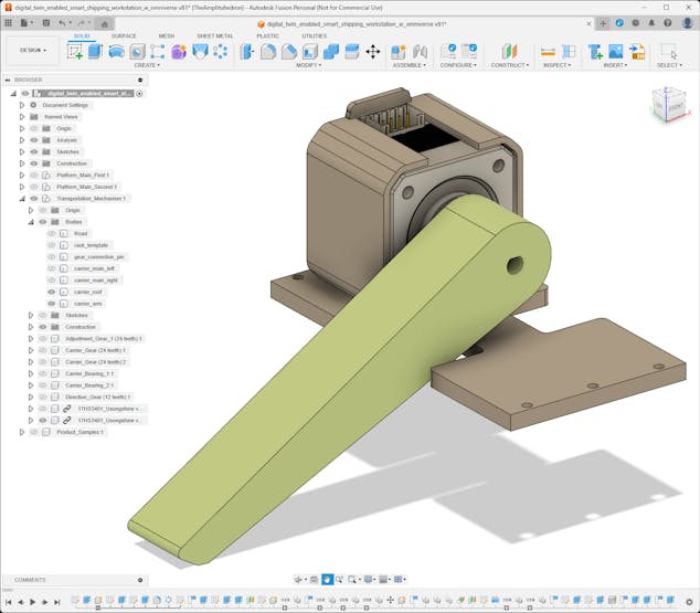
#️⃣ Then, I designed a basic carrier arm to hold the sample product still while pulling and pushing it on the transportation road.
![]()
![]()
![]()
![]()
![]()
![]()
![]()
![]()
![]()
![]()
![]()
![]()
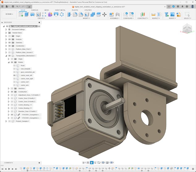
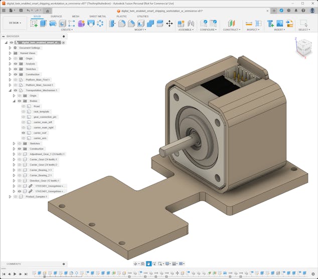
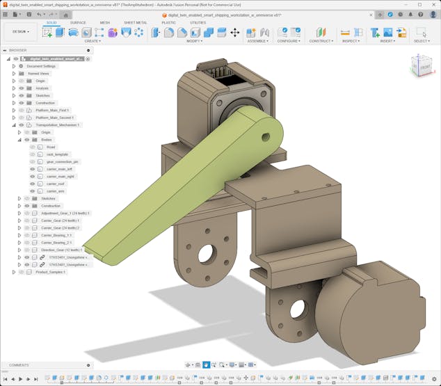
#️⃣ In this regard, the first Nema 17 stepper motor attached to the carrier drives pinions and the second one drives the carrier arm.
![]()
![]()
![]()
![]()
![]()
![]()
![]()
-
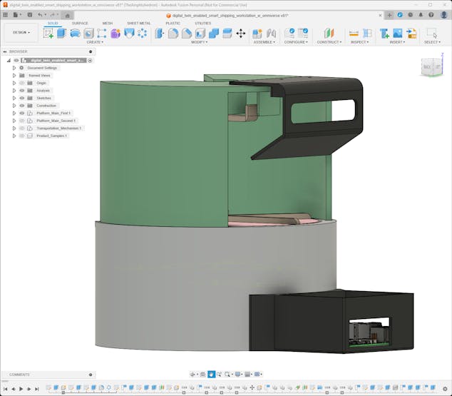
9Step 2.3: Designing complementary accessories
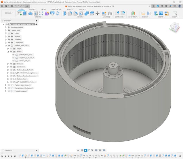
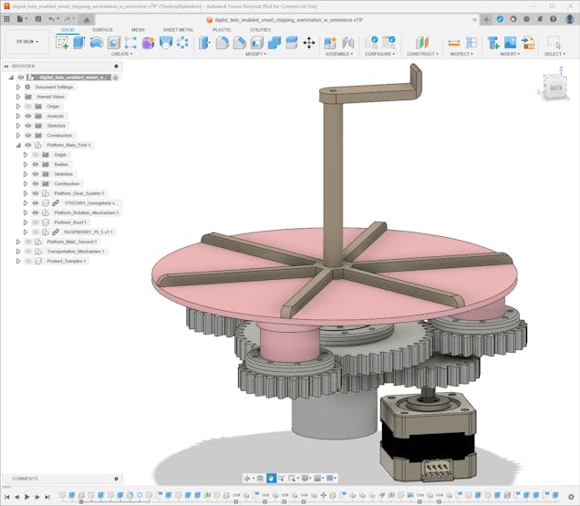
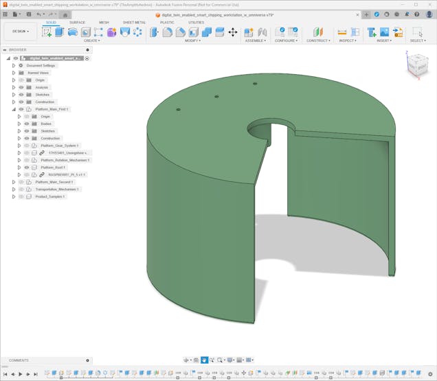
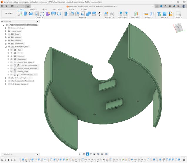
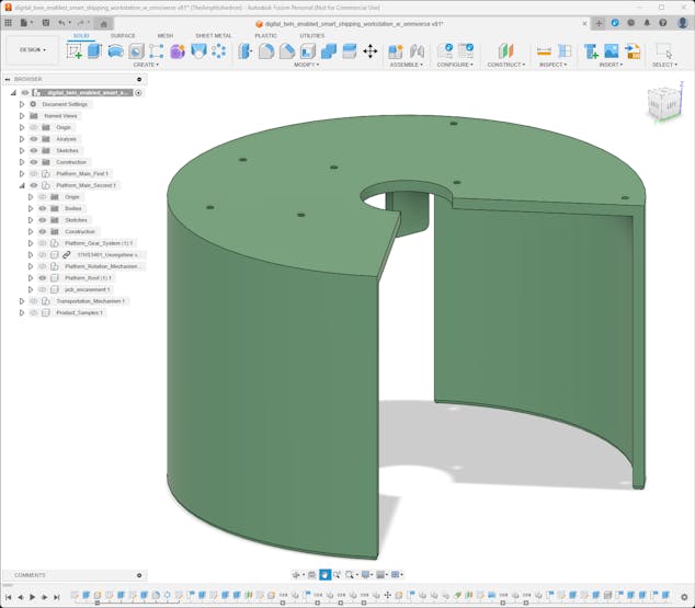
After completing mechanical 3D parts for the moving workstation components, I started to design complementary accessories, including the platform roofs, for the first and second platforms.
#️⃣ Since the first platform utilizes the IR break-beam sensor as the homing method to synchronize the 200-step per rotation pattern for 60° turns, I designed the first platform roof compatible with the IR sensor receiver and transmitter.
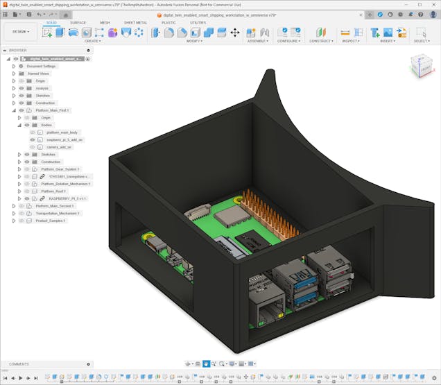
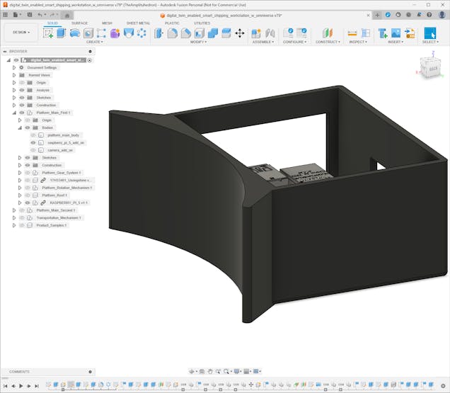
#️⃣ Then, I designed add-ons for Raspberry Pi 5 and a USB webcam since the first platform stores the sample products for automated selection and transportation process.
![]()
![]()
![]()
![]()
![]()
![]()
![]()
![]()
![]()
![]()
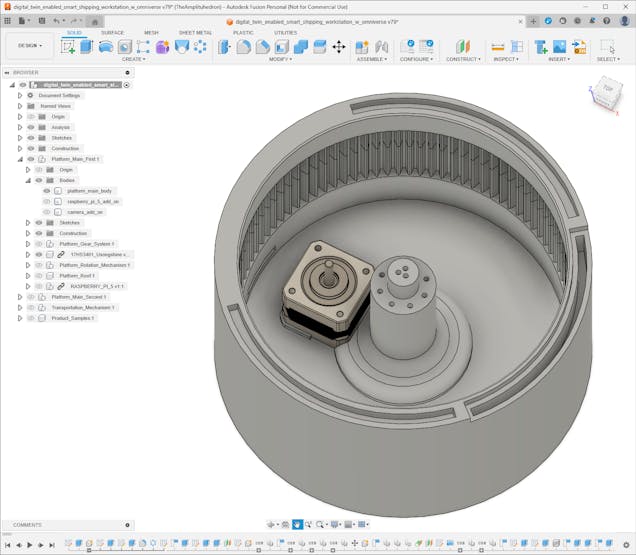
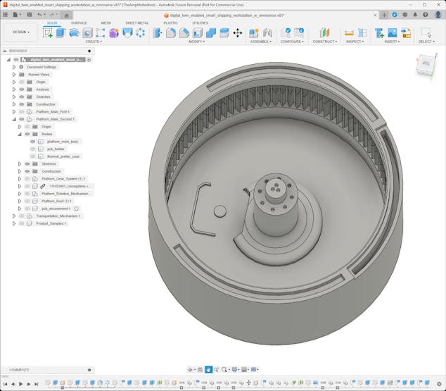
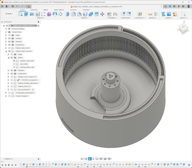
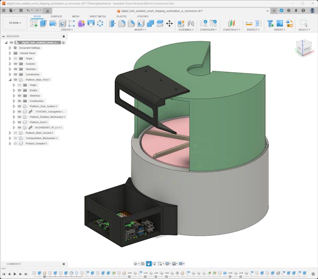
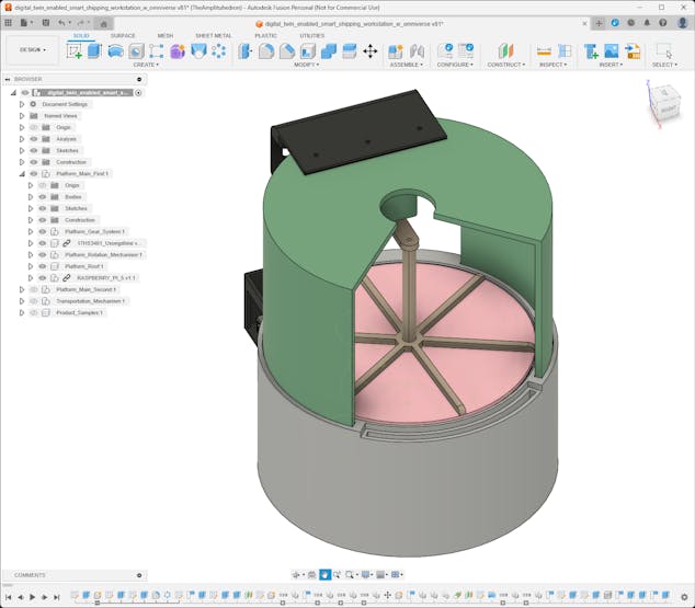
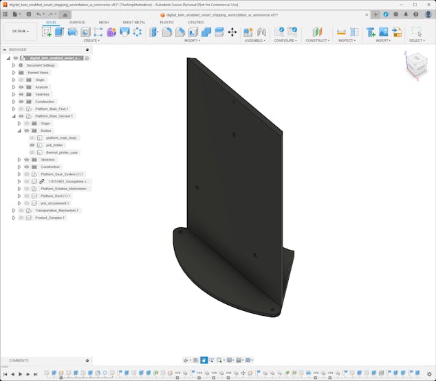
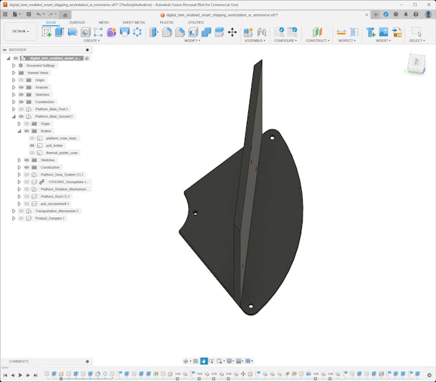
#️⃣ Since the second platform employs the micro switch as the homing method to align the face separator toward the transportation road, I designed the second platform roof compatible with the micro switch.
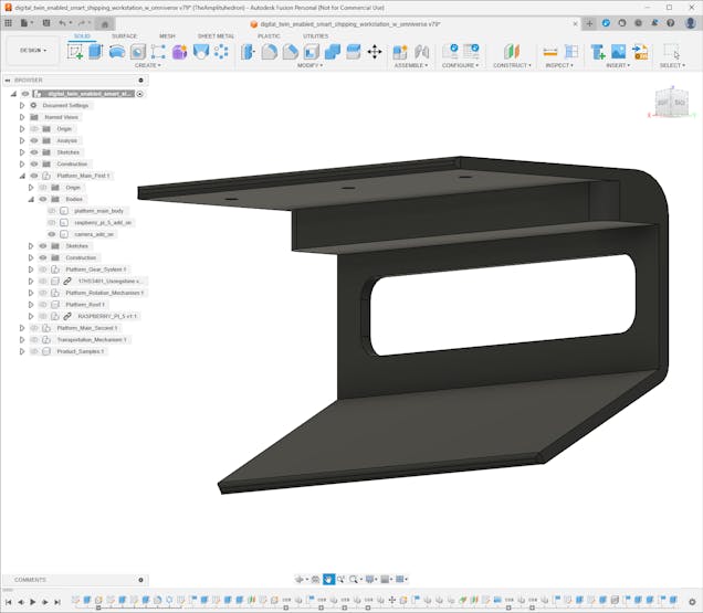
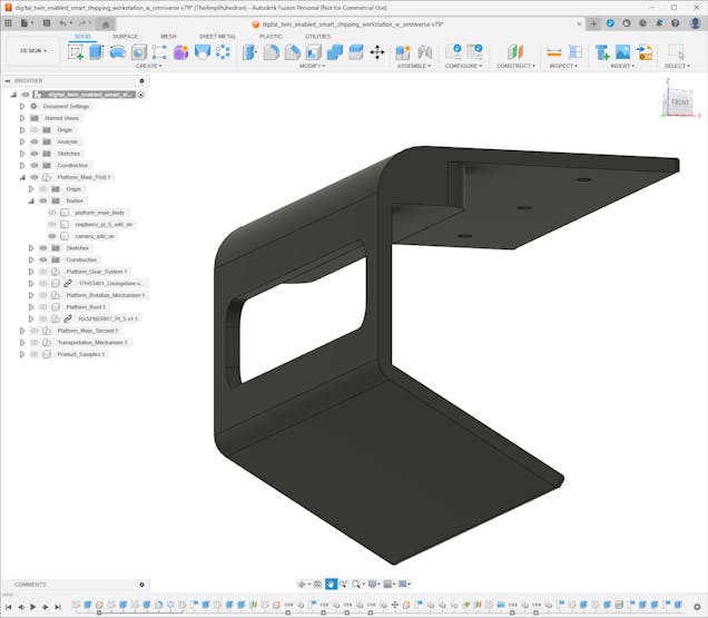
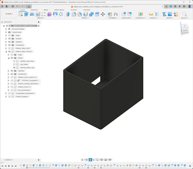
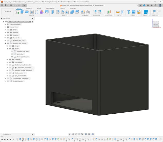
#️⃣ Then, I designed the add-on for the thermal printer and the mount for the PCB encasement since the second platform exhibits the selected and transported product.
![]()
![]()
![]()
![]()
![]()
![]()
![]()
![]()
![]()
![]()
![]()
-
10Step 2.4: Designing customized sample products
After completing the shipping workstation 3D parts, I focused on designing unique sample products since I wanted to examine the precision and efficiency of an object detection model trained on synthetic images of products that do not exist in the market.
In this regard, I was able to investigate whether it is feasible and cost-effective to initiate developing an AI-based solution for industrial operations with a synthetic data set generated from virtual product representations even before manufacturing or mass producing them.
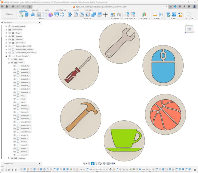
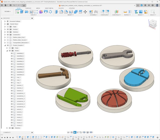
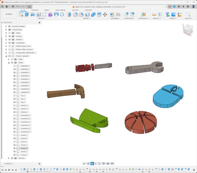
#️⃣ Compatible with the platform face separators, I designed multipart enamel pin-inspired 3D models as virtual sample products representing these objects:
- Wrench
- Mouse
- Basketball
- Teacup
- Hammer
- Screwdriver
![]()
![]()
![]()
![]()
![]()
Digital twin-enabled Smart Shipping Workstation
Exploring the digital twin synthetic data generation and AI-oriented advancements on real-world shipping operations with NVIDIA Omniverse.


Discussions
Become a Hackaday.io Member
Create an account to leave a comment. Already have an account? Log In.