 kutluhan_aktar
-
11Step 3.0: Setting up the NVIDIA Omniverse Launcher
NVIDIA Omniverse™ is a versatile and developer-friendly platform integrating OpenUSD (Universal Scene Description) and NVIDIA RTX™ rendering technologies into existing software tools and simulation workflows with officially supported APIs, SDKs, and services. In this regard, NVIDIA Omniverse provides all the necessary building tools to envision and realize large-scale and AI-enabled virtual worlds.
Since NVIDIA Omniverse is a platform optimized for industrial digitalization and physical AI simulation and provides lots of easy-to-use tools for 3D world (environment) modeling, I decided to capitalize on its enhanced simulation and rendering features while building my shipping workstation digital twin. As NVIDIA states, various enterprises employ Omniverse's state-of-the-art services to develop digital twins as testing grounds to design, simulate, operate, and optimize their products and production facilities.
Even though NVIDIA Omniverse provides developers with the NVIDIA Omniverse Kit SDK to build OpenUSD-native applications and extensions for specific tasks, I decided to utilize the Omniverse Launcher as a single-user workstation, which gives access to all Omniverse services required to build my physically accurate shipping workstation digital twin.
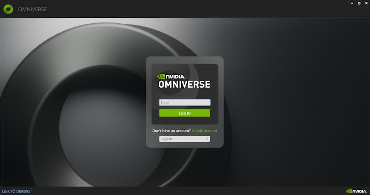
#️⃣ First, install the Omniverse Launcher here.
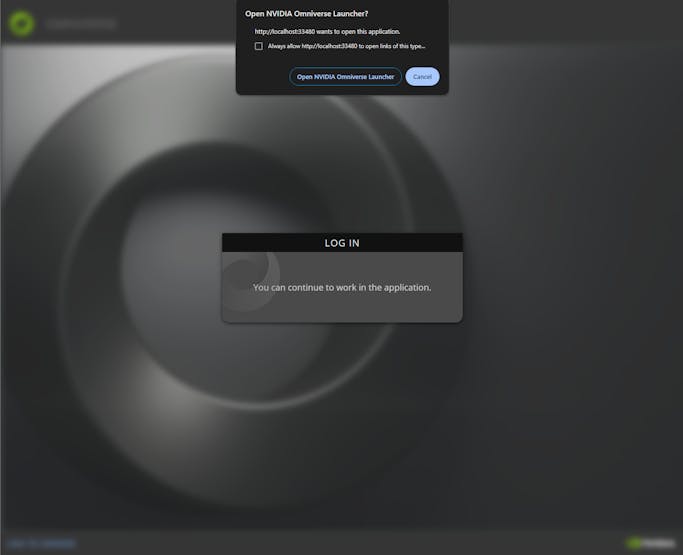
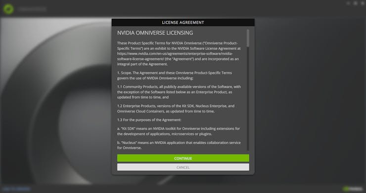
#️⃣ Then, create an NVIDIA account and confirm the license agreement to initiate the single-user workstation.
![]()
![]()
![]()
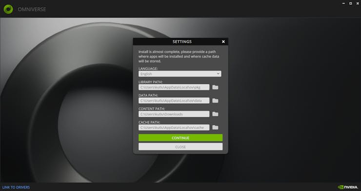
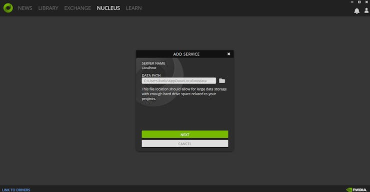
#️⃣ Assign paths to store the necessary Omniverse Launcher information locally.
![]()
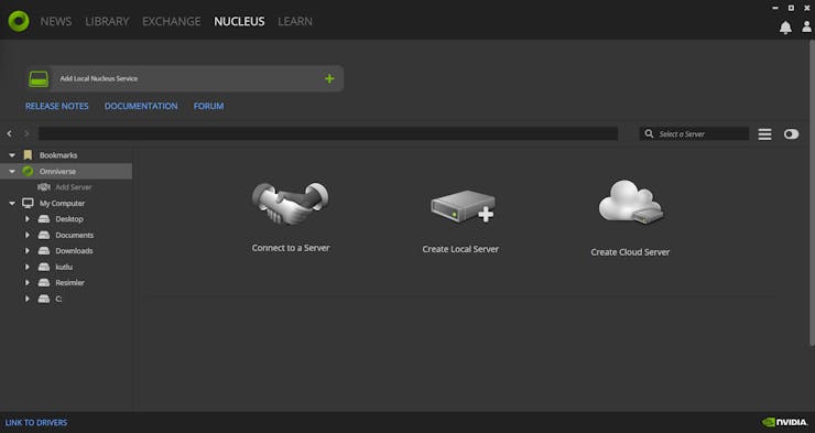
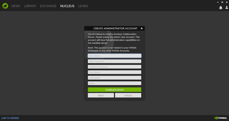
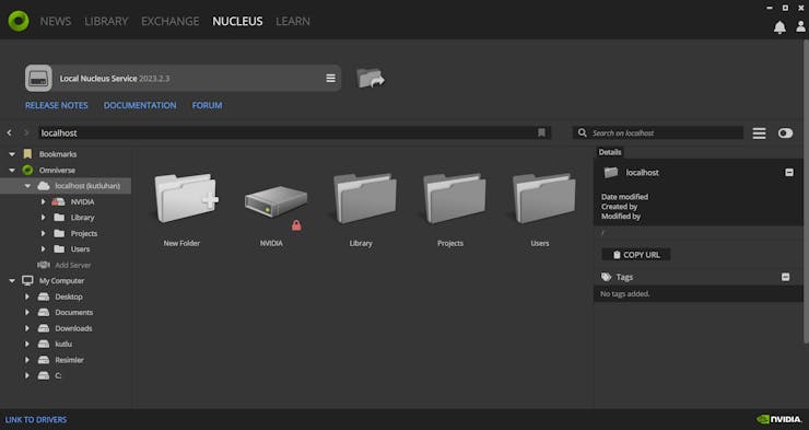
#️⃣ Since the Omniverse Launcher requires a Nucleus Collaboration Server to access all available apps, services, and assets, create a local Nucleus server and its administration account.
![]()
![]()
![]()
![]()
![]()
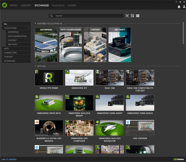
#️⃣ After establishing the local Nucleus server (service), the Launcher shows all available applications, services, connectors, and content on the Exchange tab.
![]()
-
12Step 3: Forming the shipping workstation digital twin on NVIDIA Omniverse USD Composer
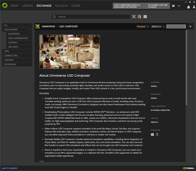
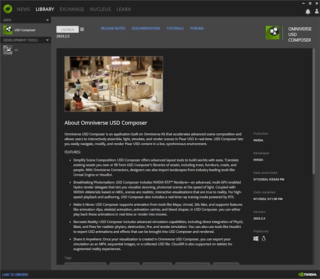
The Omniverse USD Composer is an application built on the Omniverse Kit and provides advanced layout tools and simulation capabilities, including but not limited to NVIDIA RTX™ Renderer and physics extension, for generating visually compelling and physically accurate worlds.
Since the USD Composer allows developers to import existing assets (designs) and render large-scale scenes with user-friendly simulation tools, I decided to set up the USD Composer on the Omniverse Launcher to build my shipping workstation digital twin.
![]()
![]()
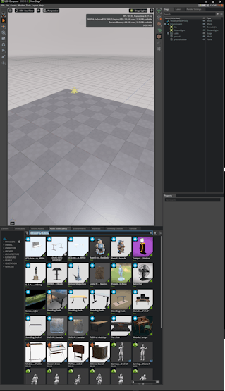
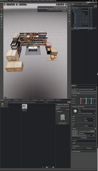
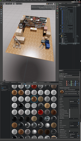
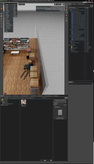
After installing the USD Composer, I started to work on producing a realistic scenery for industrial-level shipping operations.
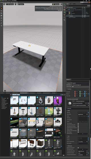
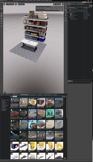
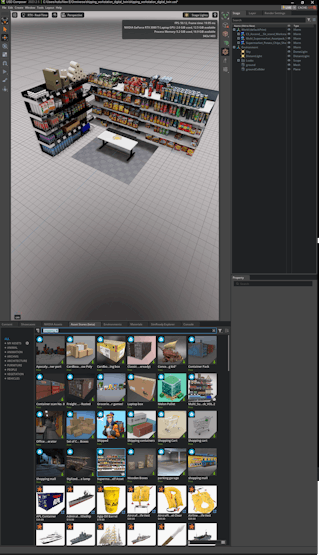
Plausibly, NVIDIA Omniverse provides built-in asset (3D model) and material libraries for various use cases. Also, the USD Composer includes the Asset Store displaying all available high-quality 3D models from diverse third-party content libraries.
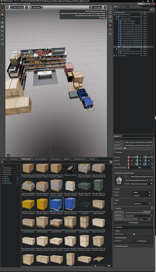
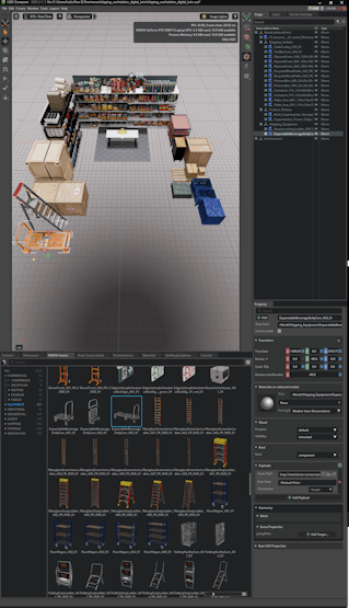
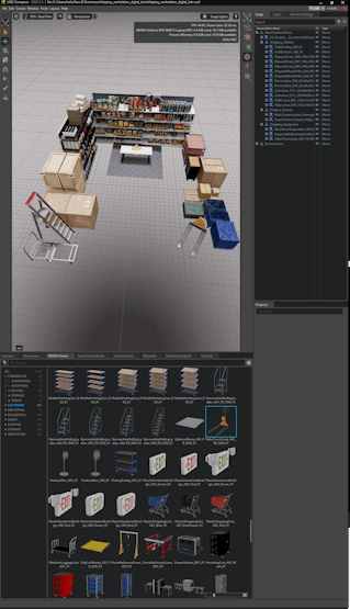
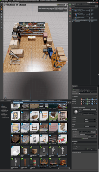
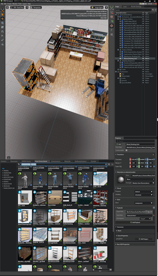
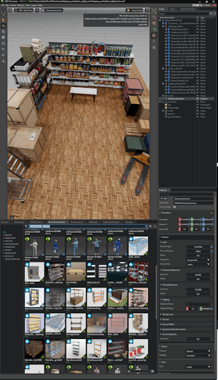
#️⃣ First, I scrutinized all available assets provided by Omniverse (default) and Sketchfab (free Creative Commons-licensed) to produce a suitable scenery, including a close replica of my standing desk.
![]()
![]()
![]()
![]()
![]()
![]()
![]()
![]()
![]()
![]()
![]()
![]()
![]()
![]()
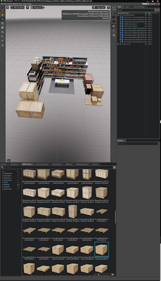
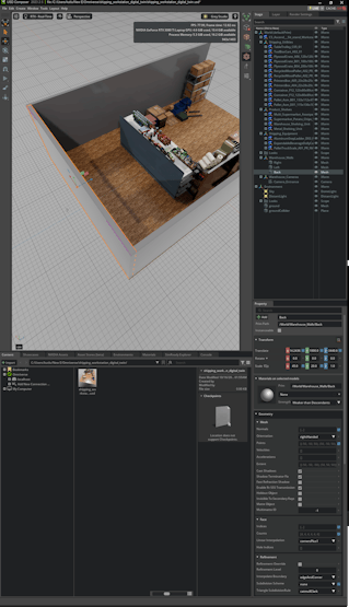
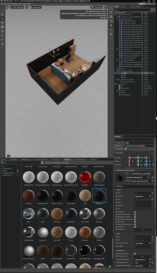
#️⃣ Then, I designed some custom assets with the integrated Omniverse tools to finalize my shipping warehouse scenery.
![]()
![]()
![]()
![]()
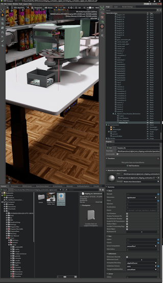
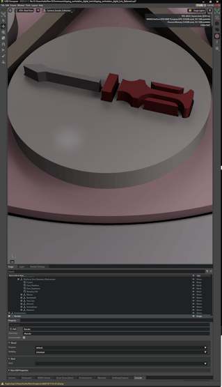
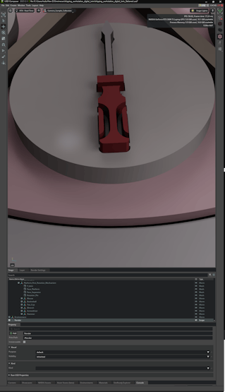
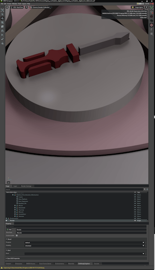
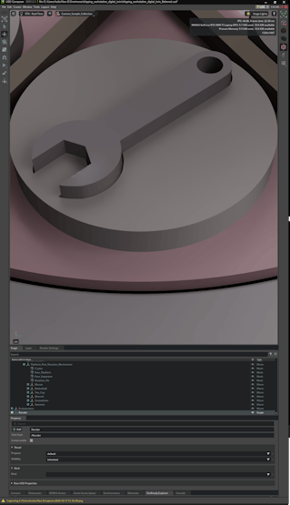
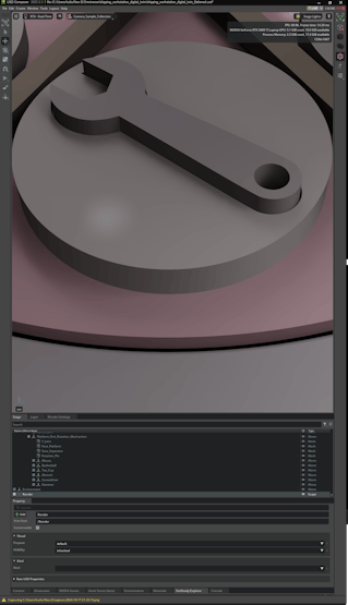
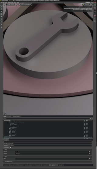
#️⃣ After completing my shipping warehouse scenery, I imported the virtual shipping workstation in the OBJ format.
#️⃣ Since the Omniverse Launcher can automatically detect and assign Fusion 360 material, color, and texture configurations, the USD Composer rendered the virtual shipping workstation to produce a flawless digital twin.
![]()
![]()
![]()
![]()
![]()
![]()
![]()
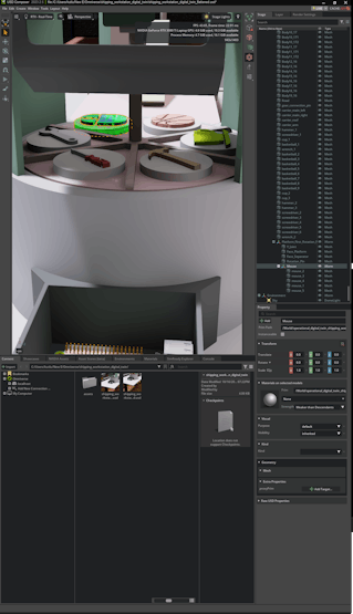
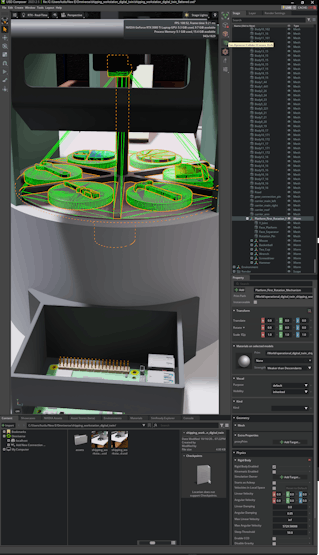
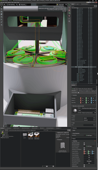
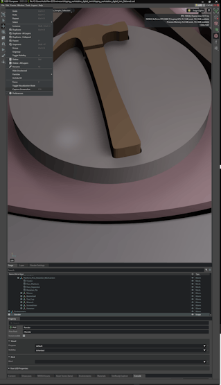
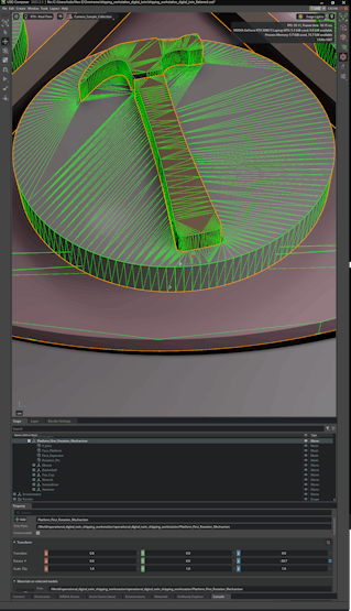
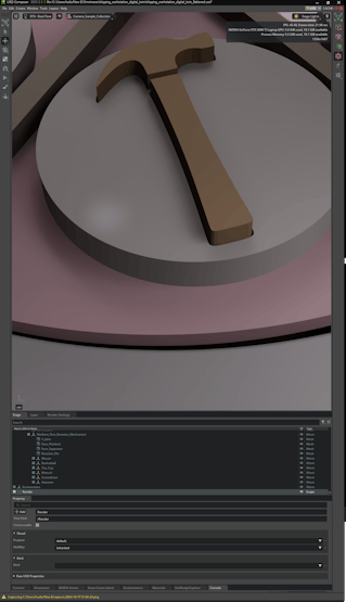
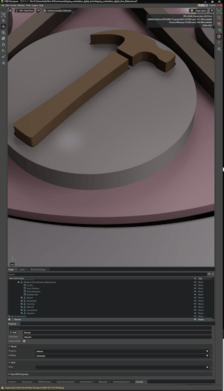
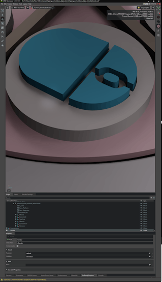
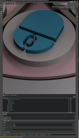
#️⃣ To move the first rotating platform and sample products as a single object via the physics extension, I tried to group all associated models under a new Xform. However, it was not possible since these models were references from the original OBJ file.
#️⃣ To solve this issue, I saved the Omniverse stage again by utilizing the Save Flattened As option to merge all 3D models. Then, I was able to modify and group the associated models easily.
![]()
![]()
![]()
![]()
![]()
![]()
![]()
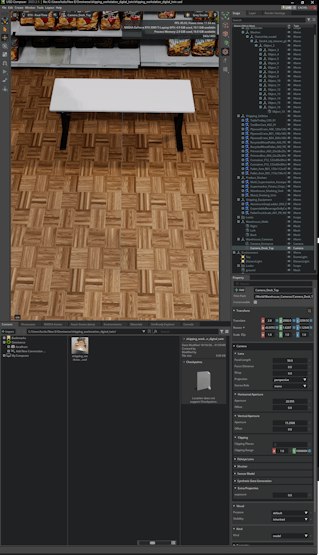
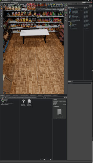
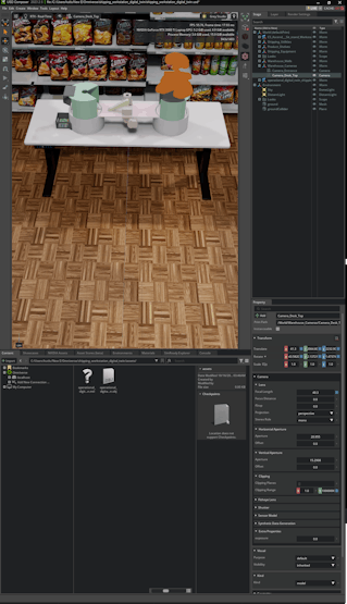
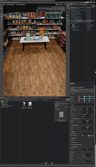
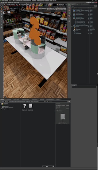
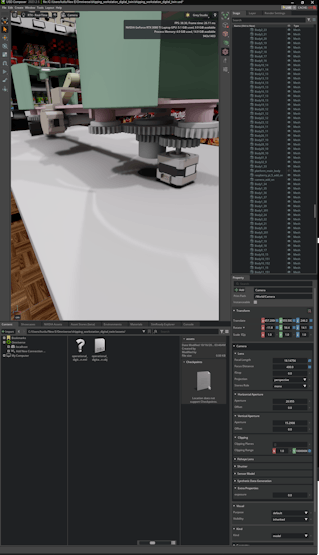
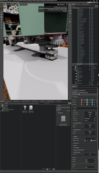
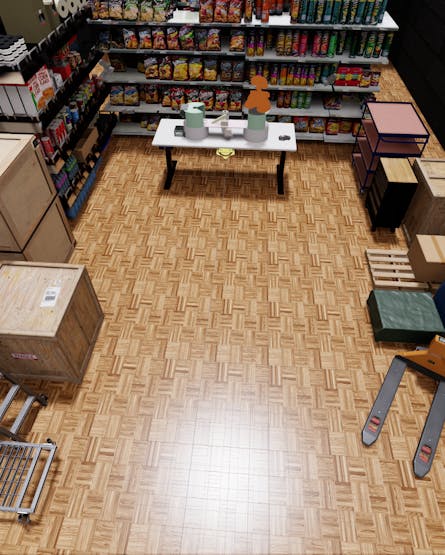
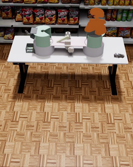
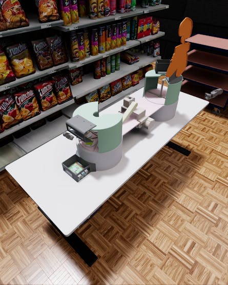
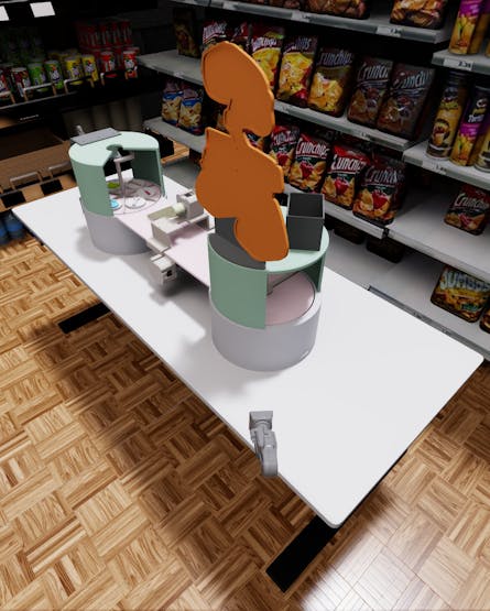
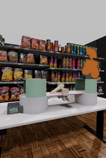
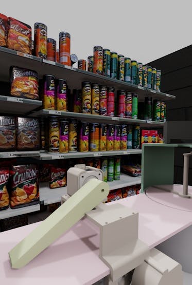
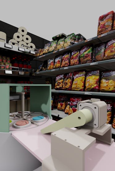
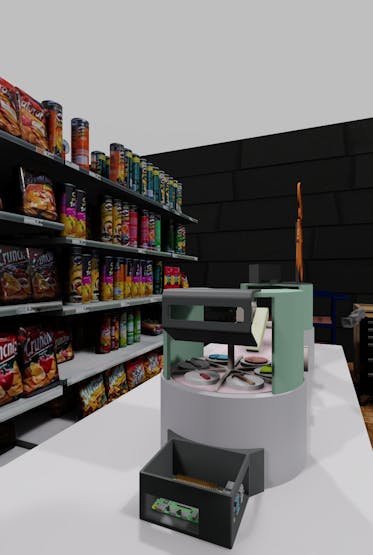
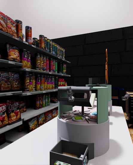
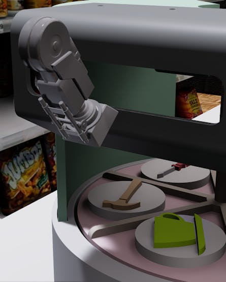
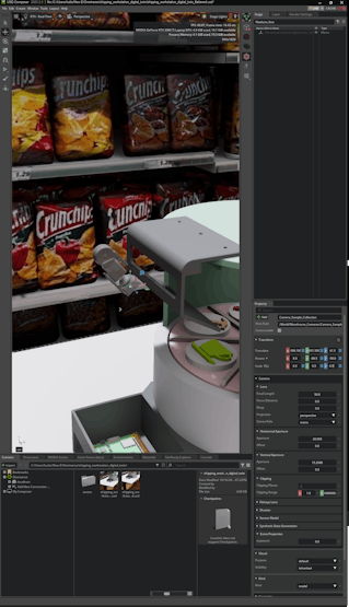
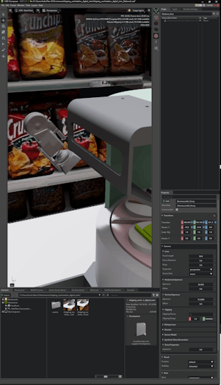
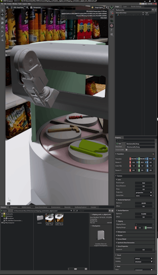
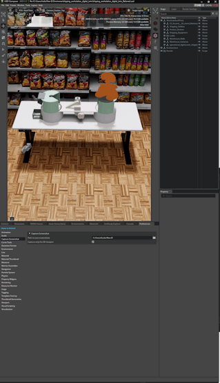
#️⃣ After producing the shipping workstation digital twin, I created a few cameras to survey the virtual workstation and capture synthetic sample product images effortlessly.
![]()
![]()
![]()
![]()
![]()
![]()
![]()
![]()
![]()
![]()
![]()
![]()
-
13Step 4: Constructing a synthetic data set of customized sample products via NVIDIA Omniverse
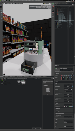
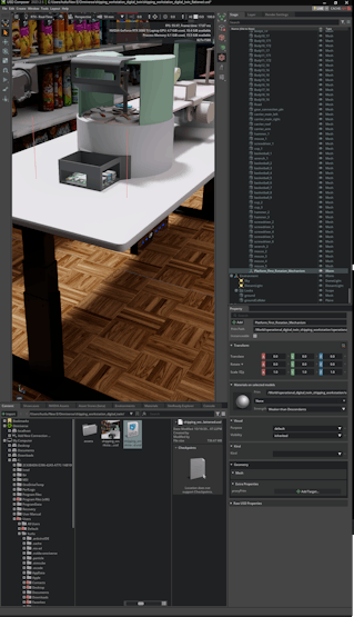
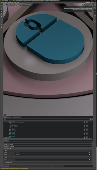
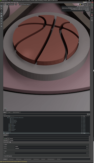
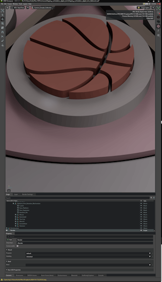
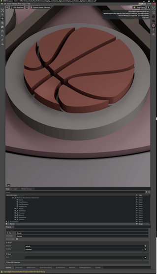
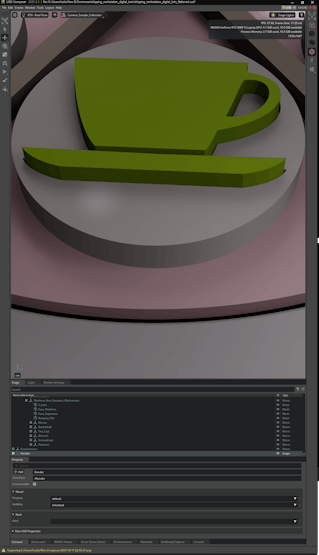
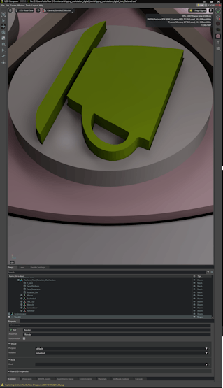
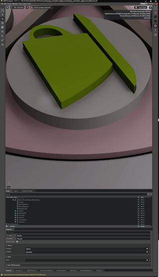
#️⃣ After preparing the shipping workstation digital twin for synthetic data collection, I experimented with camera, lighting, and rendering configurations to create optimal conditions.
#️⃣ Then, I applied the built-in Capture Screenshot (F10) feature by activating the Capture only the 3D viewport option so as to construct my synthetic data set of unique sample products in various poses.
![]()
![]()
![]()
![]()
![]()
![]()
![]()
![]()
![]()
![]()
![]()
![]()
![]()
![]()
![]()
![]()
![]()
![]()
![]()
![]()
![]()
![]()
![]()
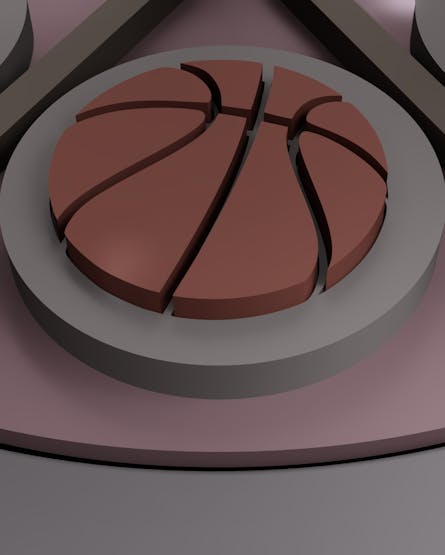
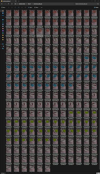
🖼️ Synthetic data samples:
![]()
![]()
![]()
![]()
![]()
![]()
![]()
![]()
![]()
![]()
![]()
![]()
![]()
-
14Step 5: Setting up LAMP web server, Edge Impulse CLI, and Linux Python SDK on Raspberry Pi 5
After constructing my synthetic data set, I was going to build my object detection model before proceeding with real-world shipping workstation preparations. However, while trying to upload my synthetic data samples generated by NVIDIA Omniverse USD Composer, I noticed most of them were refused by the Edge Impulse data uploader by being tagged as duplicated. I even attempted to upload six individual samples for each product, nonetheless, the issue still resumed. Thus, I decided to set up Raspberry Pi 5 earlier to perform the tasks required by the real-world shipping workstation and upload samples directly.
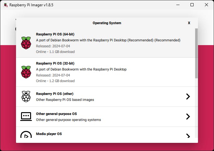
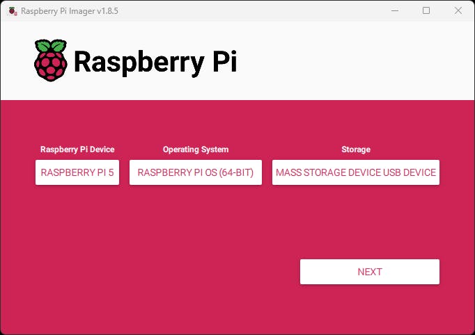
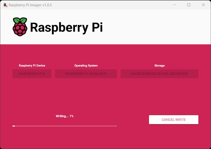
#️⃣ First, I installed the Raspberry Pi 5-compatible operating system image on a microSD card and initiated Raspberry Pi 5.
❗⚡ Note: While testing peripherals, I encountered under-voltage issues and purchased the official Raspberry Pi 5 27W USB-C power supply.
![]()
![]()
![]()
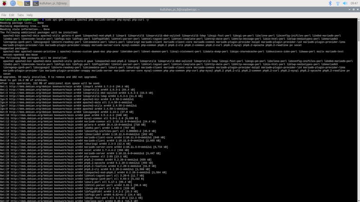
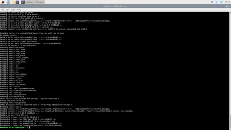
#️⃣ After initiating Raspberry Pi 5 successfully, I set up an Apache web server with a MariaDB database. I also installed PHP MySQL and cURL packages to host and enable the web workstation application features.
sudo apt-get install apache2 php mariadb-server php-mysql php-curl -y
![]()
![]()
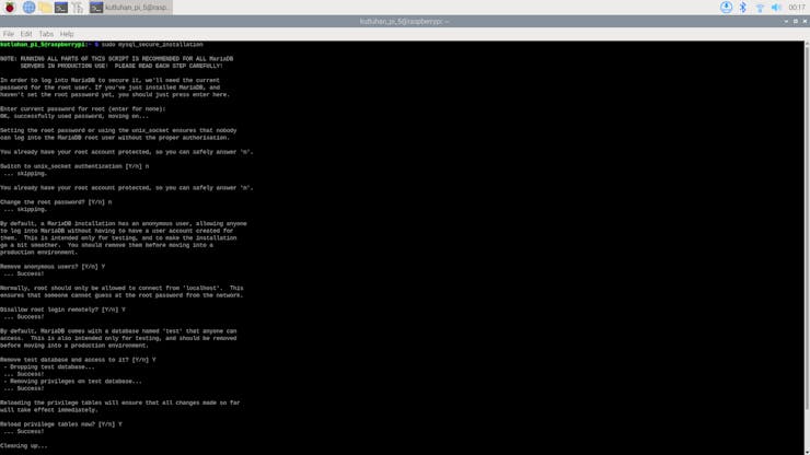
#️⃣ To utilize the MariaDB database, I created a new user and followed the secure installation prompt.
sudo mysql_secure_installation
![]()
#️⃣ After setting up the LAMP web server, I installed the Edge Impulse CLI by following the official instructions for Raspbian OS.
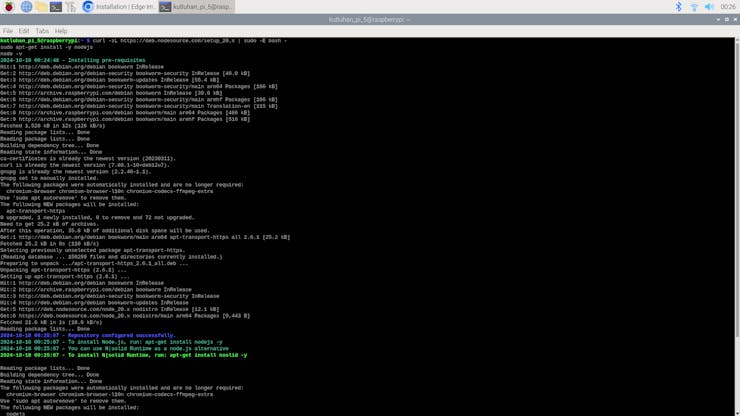
#️⃣ First, I downloaded the latest Node.js version since versions older than 20.x may lead to installation issues or runtime errors.
curl -sL https://deb.nodesource.com/setup_20.x | sudo -E bash -
sudo apt-get install -y nodejs
node -v
#️⃣ Then, I installed the available CLI tools.
npm install -g edge-impulse-cli
![]()
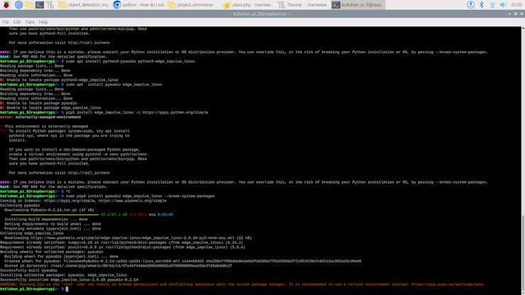
#️⃣ After setting up the Edge Impulse CLI, I installed the Edge Impulse Linux Python SDK to run Edge Impulse machine learning models via Python.
❗ If you do not run a virtual environment on Pi 5, the system may throw an error while trying to install packages via pip. To simply solve this issue, you can add --break-system-packages.
sudo apt-get install libatlas-base-dev libportaudio2 libportaudiocpp0 portaudio19-dev python3-pip
sudo pip3 install pyaudio edge_impulse_linux --break-system-packages
![]()
![]()
-
15Step 6: Building an object detection model (FOMO) w/ Edge Impulse Enterprise
Since Edge Impulse provides developer-friendly tools for advanced AI applications and supports almost every development board due to its model deployment options, I decided to utilize Edge Impulse Enterprise to build my object detection model. Also, Edge Impulse Enterprise incorporates elaborate model architectures for advanced computer vision applications and optimizes the state-of-the-art vision models for edge devices and single-board computers such as Raspberry Pi 5.
Among the diverse machine learning algorithms provided by Edge Impulse, I decided to employ FOMO (Faster Objects, More Objects) since it is a novel algorithm optimized for highly constrained devices with a brilliant heat map to bounding boxes technique.
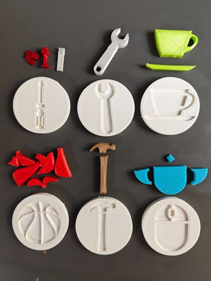
While labeling my synthetic image samples, I simply applied the names of the represented real-world objects:
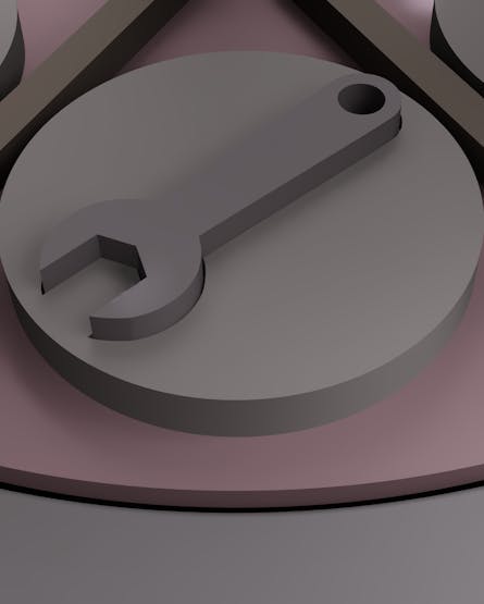
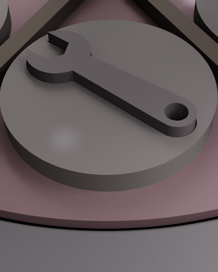
- wrench
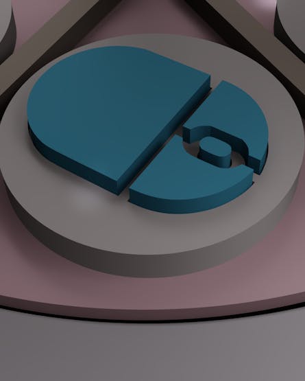
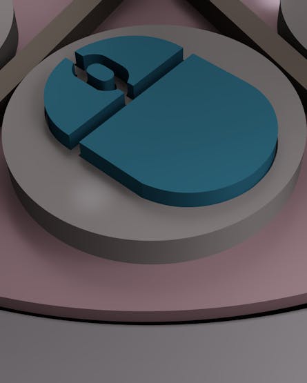
- mouse
- basketball
- tea_cup
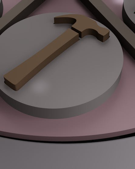
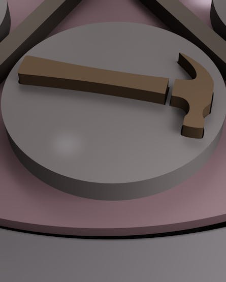
- hammer
- screwdriver
Plausibly, Edge Impulse Enterprise enables developers with advanced tools to build, optimize, and deploy each available machine learning algorithm as supported firmware for nearly any device you can think of. Therefore, after training and validating, I was able to deploy my FOMO model as a Linux (AARCH64) application (.eim) compatible with Raspberry Pi 5.
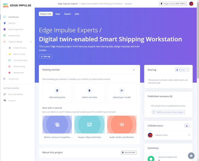
You can inspect my object detection model (FOMO) on Edge Impulse as a public project.
-
16Step 6.1: Uploading and labeling training and testing images (samples)
#️⃣ To utilize the advanced AI tools provided by Edge Impulse, register here and create a new project.
![]()
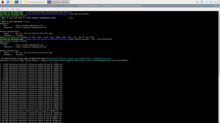
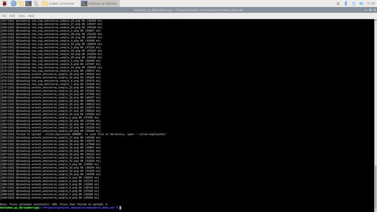
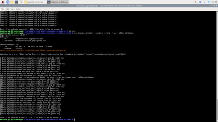
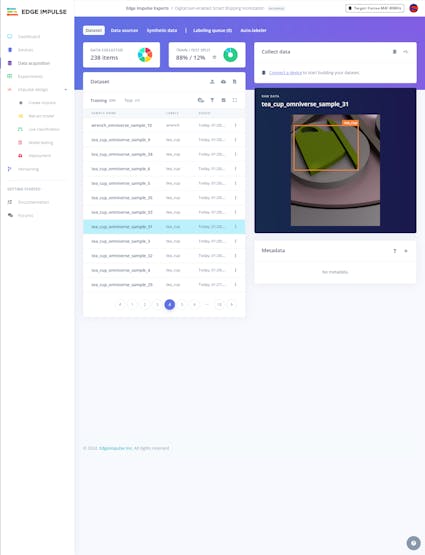
As mentioned earlier, the Edge Impulse data uploader refused most of the synthetic image samples generated by the Omniverse USD Composer. Thus, I set up the Edge Impulse CLI to upload my synthetic data set from Raspberry Pi 5 to my Edge Impulse project directly.
Since the Edge Impulse CLI allows developers to override duplicate sample detection, I was able to upload all of my synthetic data set as training and testing samples without any problem.
❗ Use --category to choose the data category (training or testing) and add --allow-duplicates to override duplicate detection.
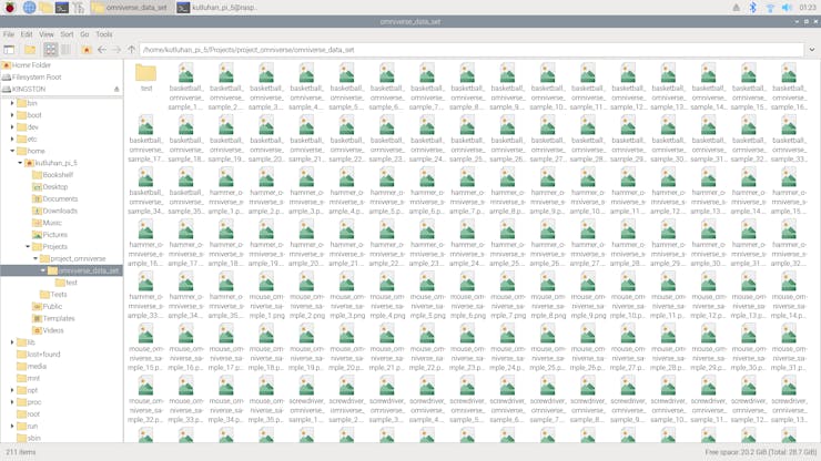
cd Projects/project_omniverse/omniverse_data_set
edge-impulse-uploader *.png --allow-duplicates
edge-impulse-uploader --category testing *.png --allow-duplicates
![]()
![]()
![]()
![]()
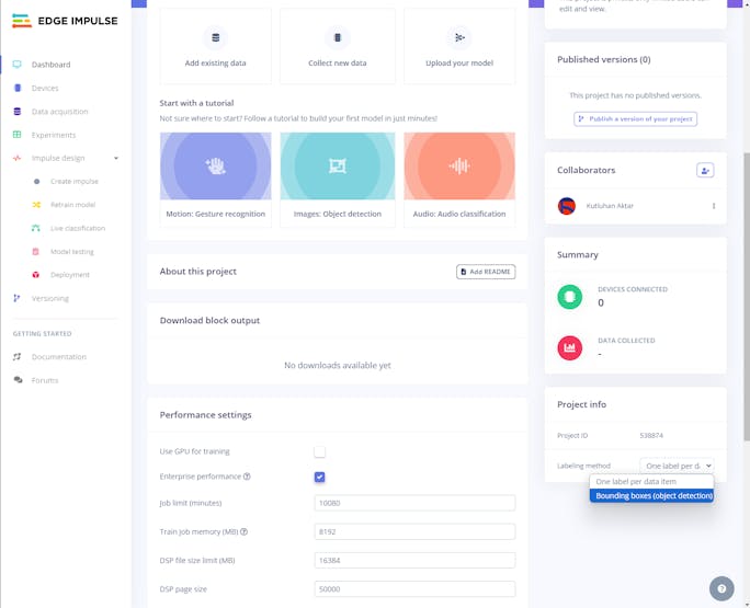
#️⃣ To employ the bounding box labeling tool for object detection models, go to Dashboard ➡ Project info ➡ Labeling method and select Bounding boxes (object detection).
![]()
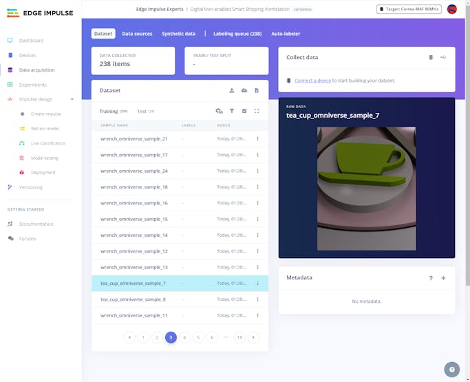
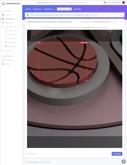
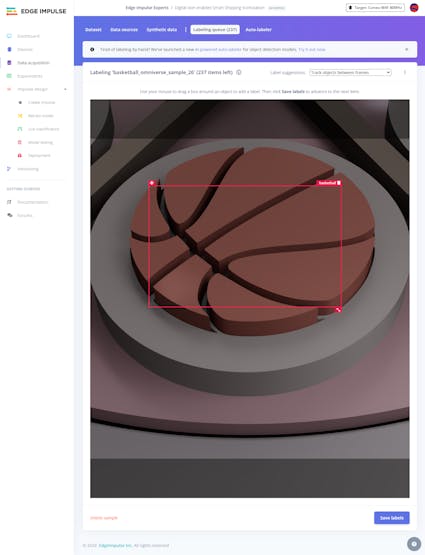
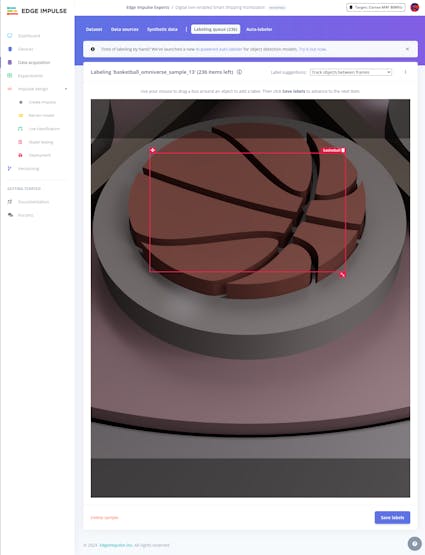
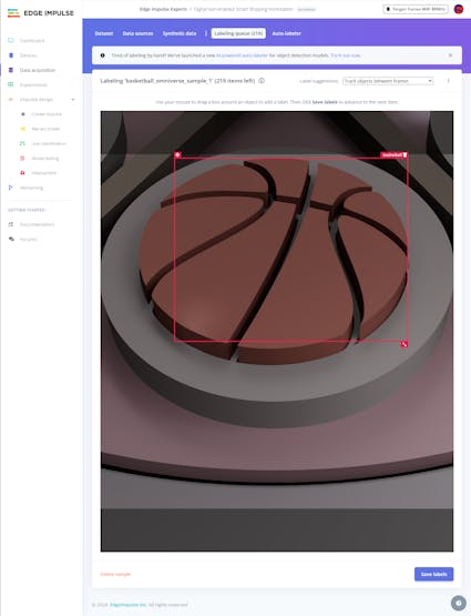
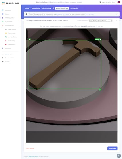
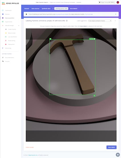
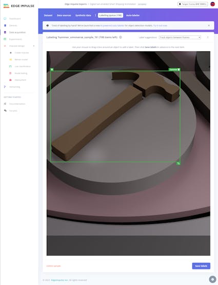
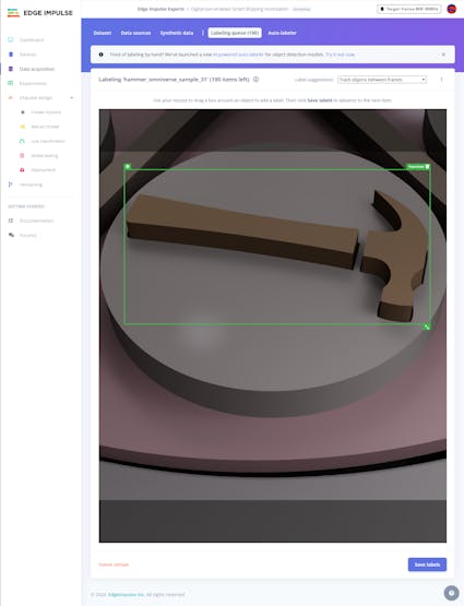
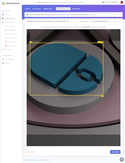
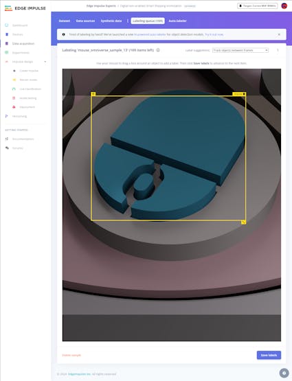
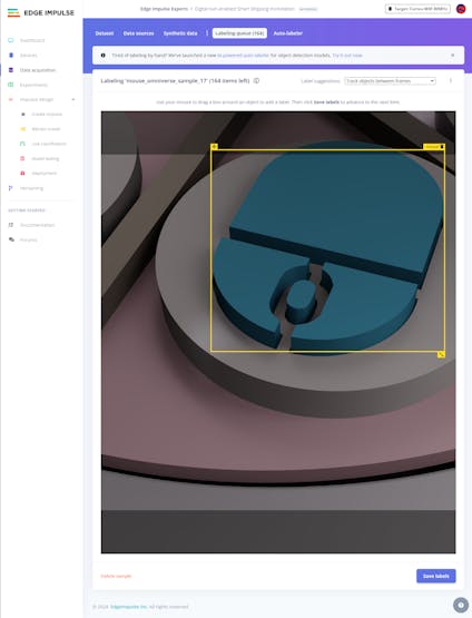
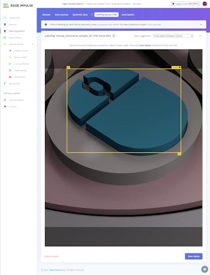
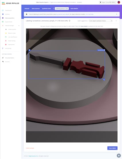
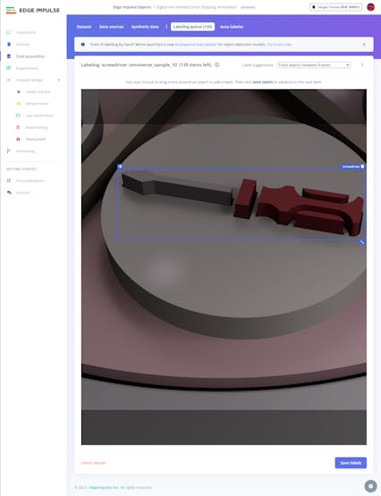
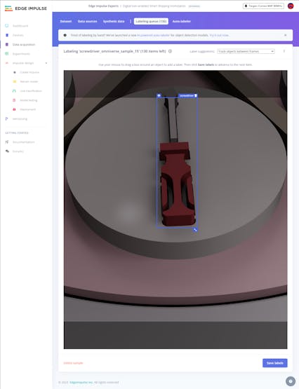
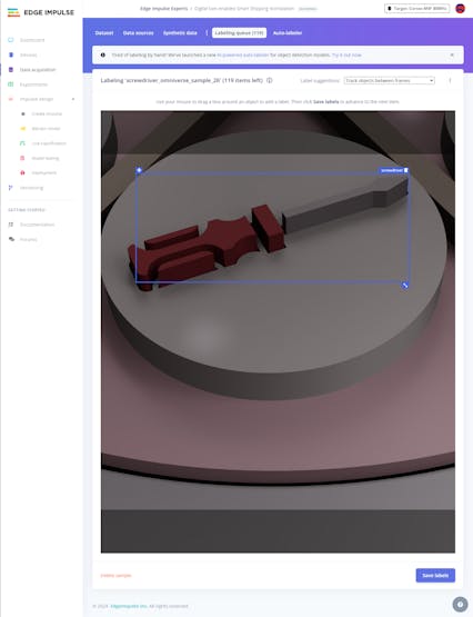
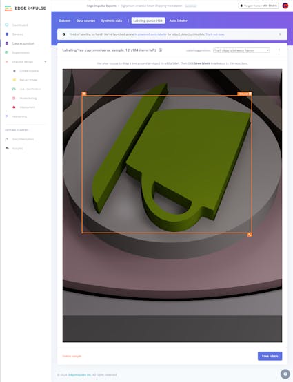
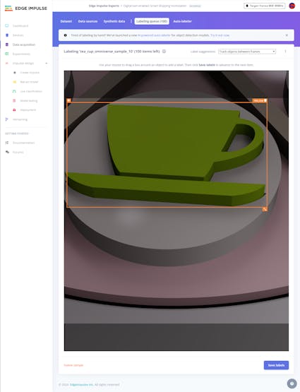
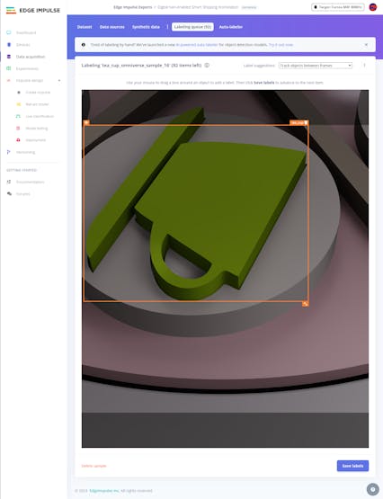
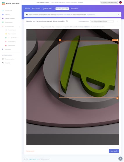
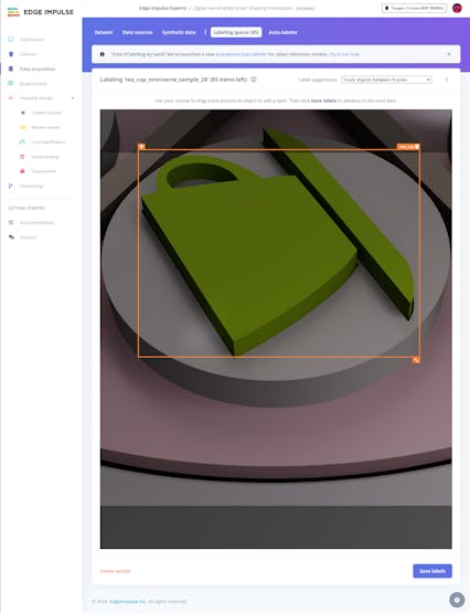
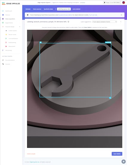
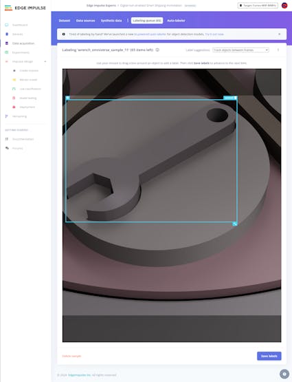
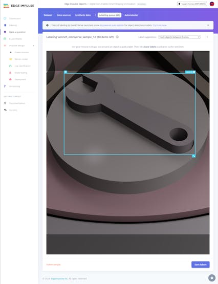
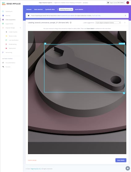
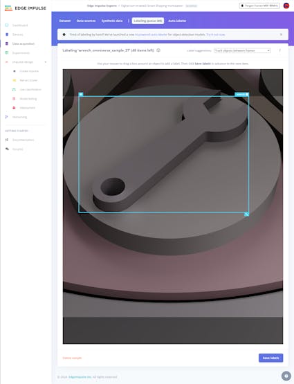
After uploading my synthetic data set of unique sample products and activating the bounding box labeling tool, I started to draw bounding boxes around the target objects for each image sample.
#️⃣ Go to Data acquisition ➡ Labeling queue to access all unlabeled items (training and testing) remaining in the given data set.
#️⃣ After drawing bounding boxes around target objects, click the Save labels button to label an image sample. Then, repeat this process until all samples have at least one labeled target object.
![]()
![]()
![]()
![]()
![]()
![]()
![]()
![]()
![]()
![]()
![]()
![]()
![]()
![]()
![]()
![]()
![]()
![]()
![]()
![]()
![]()
![]()
![]()
![]()
![]()
![]()
![]()
![]()
![]()
![]()
-
17Step 6.2: Training the FOMO model on synthetic sample product images
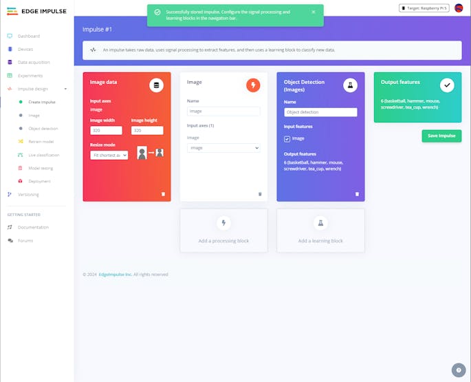
An impulse is a custom machine learning application processed and optimized by Edge Impulse. I created my impulse by employing the Image processing block and the Object Detection (Images) learning block.
The Image processing block optionally turns the input image format to grayscale or RGB and generates a features array from the passed raw image.
The Object Detection (Images) learning block represents the accessible machine learning algorithms to perform object detection.
#️⃣ Go to the Create impulse page, set the image dimensions to 320, select the Fit shortest axis resize mode so as to scale (resize) the given image samples precisely, and click Save Impulse.
![]()
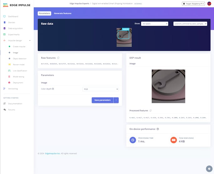
#️⃣ To modify the raw features in the applicable format, go to the Image page, set the Color depth parameter as RGB, and click Save parameters.
![]()
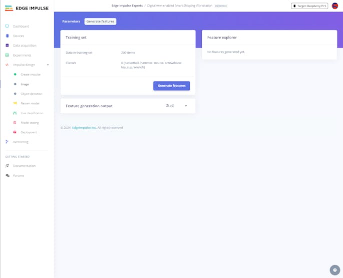
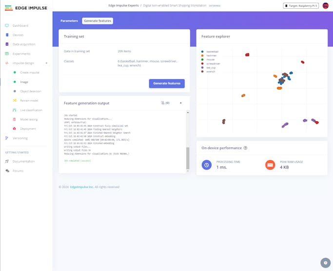
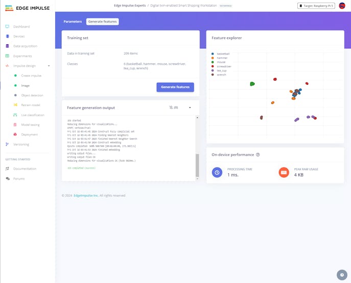
#️⃣ Then, click Generate features to apply the Image processing block to training image samples.
![]()
![]()
![]()
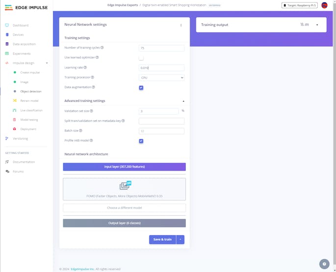
#️⃣ After generating features successfully, navigate to the Object detection page and click Start training.
According to my prolonged experiments, I modified the neural network settings and architecture to achieve reliable accuracy and validity:
📌 Neural network settings:
- Number of training cycles ➡ 75
- Learning rate ➡ 0.010
- Validation set size ➡ 3%
📌 Neural network architecture:
- FOMO (Faster Objects, More Objects) MobileNetV2 0.35
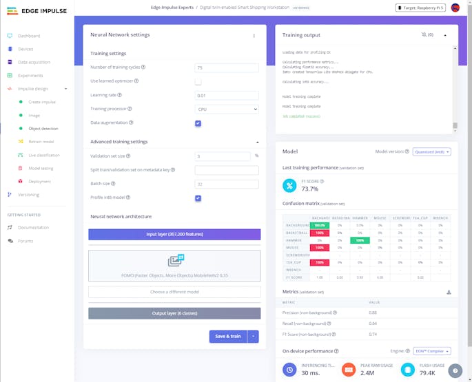
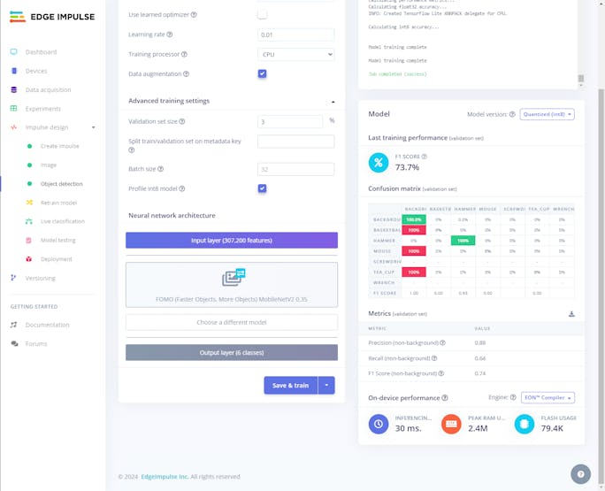
After training with the given configurations, Edge Impulse evaluated the F1 score (accuracy) as 73.7% due to the modest volume of the validation set.
![]()
![]()
![]()
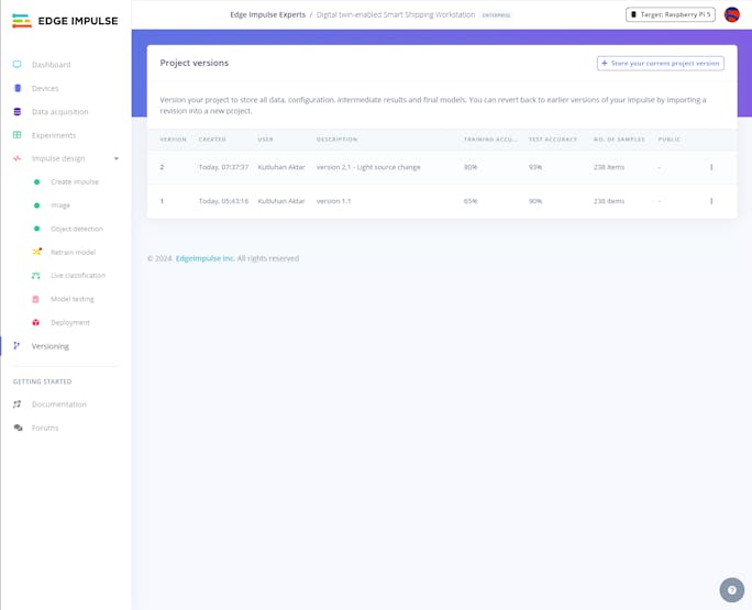
#️⃣ Since I decided to experiment with different model and simulation (render) configurations consecutively, I utilized two versions of the same model to achieve the results I wanted faster.
![]()
-
18Step 6.3: Evaluating the model accuracy and deploying the validated model
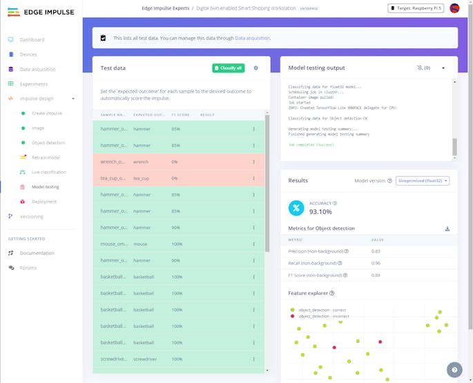
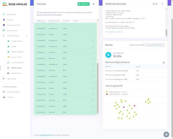
By applying the given testing samples, Edge Impulse evaluated the model accuracy (precision) as 93.10%.
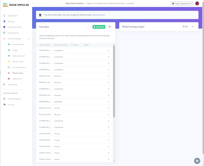
#️⃣ To validate the trained model, go to the Model testing page and click Classify all.
![]()
![]()
![]()
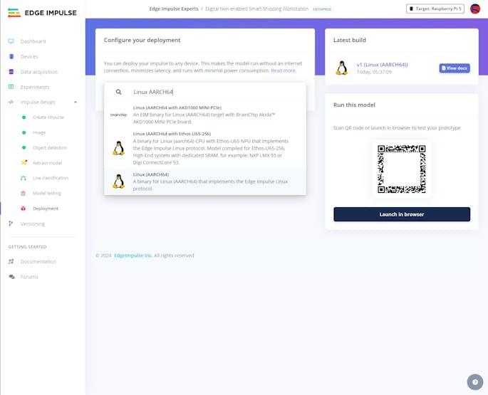
Then, I deployed the validated model as a fully optimized and customizable Linux (AARCH64) application (.eim).
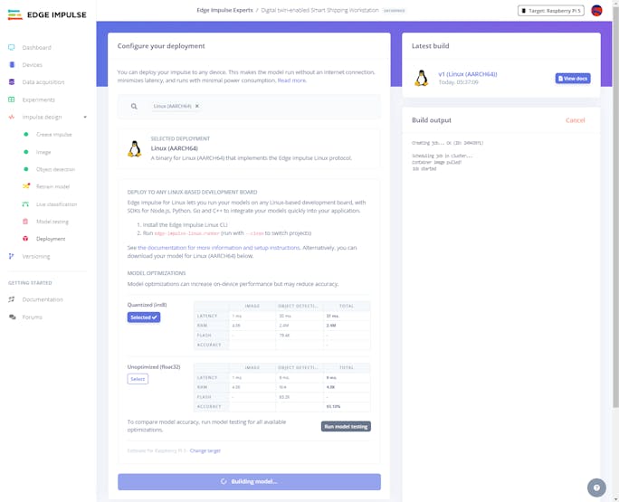
#️⃣ Navigate to the Deployment page and search for Linux (AARCH64).
#️⃣ Choose the Quantized (int8) optimization option to get the optimum performance while running the deployed model.
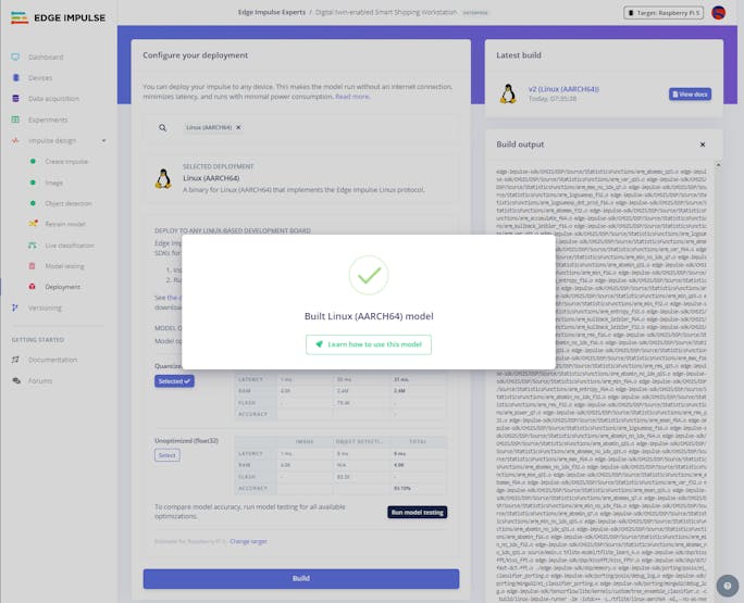
#️⃣ Finally, click Build to download the model as a Linux (AARCH64) application (.eim) compatible with Raspberry Pi 5.
![]()
![]()
![]()
-
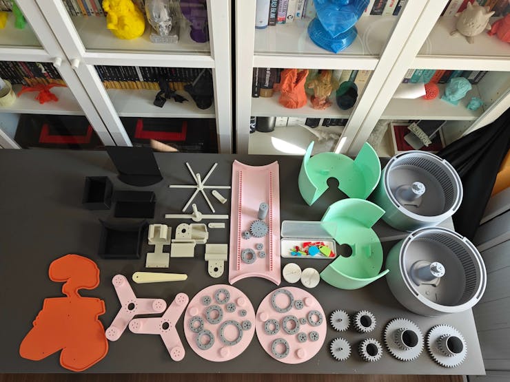
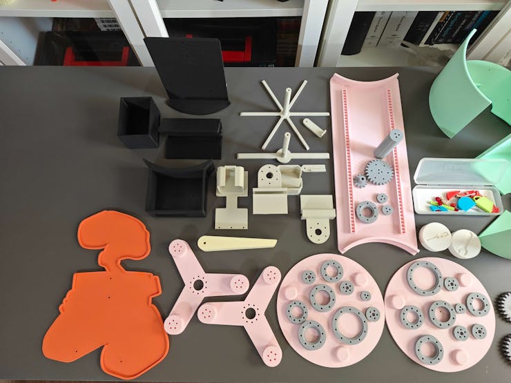
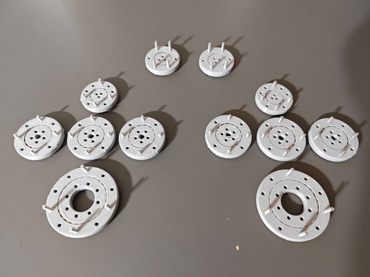
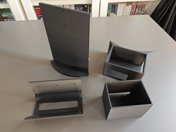
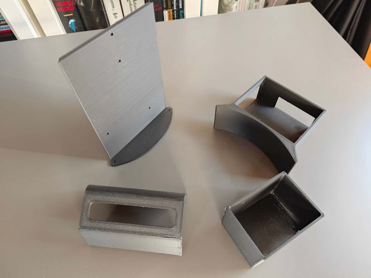
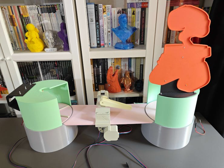
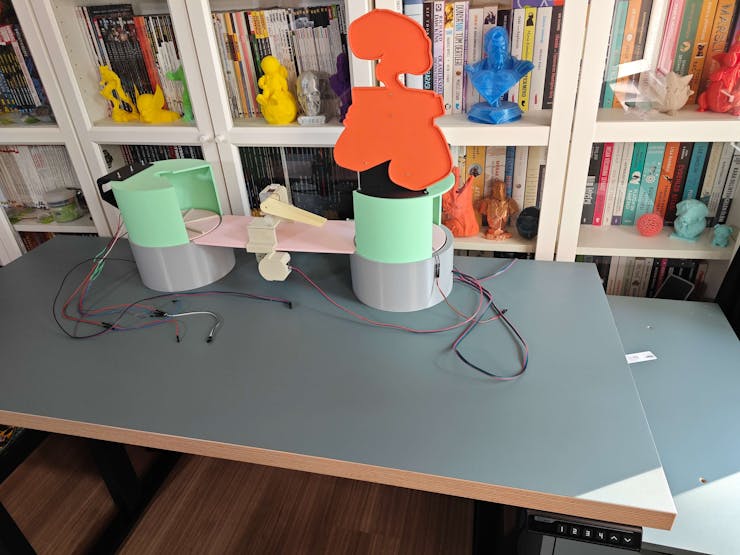
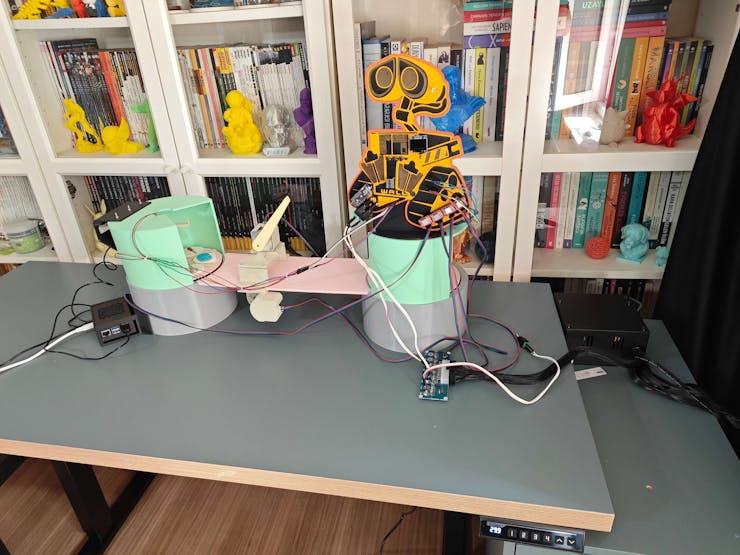
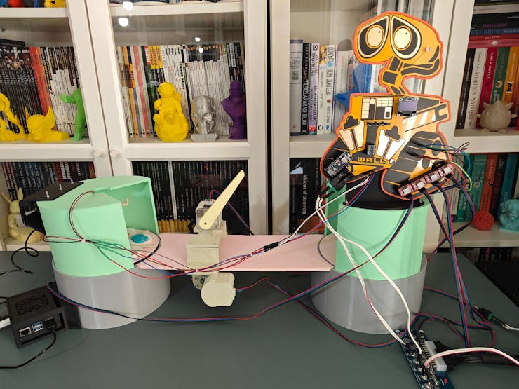
19Step 7: Printing and assembling 3D parts of the virtual shipping workstation to build its real-world counterpart
After concluding my assignments with the shipping workstation digital twin on NVIDIA Omniverse USD Composer, I started to work on building its real-world counterpart.
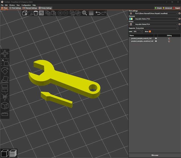
#️⃣ First, on Autodesk Fusion 360, I exported all virtual shipping workstation 3D parts in the STL format individually.
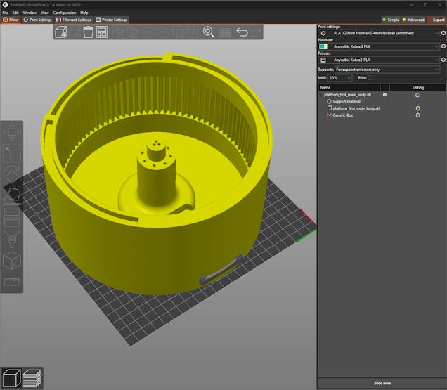
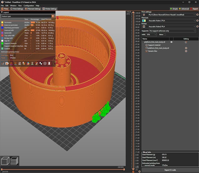
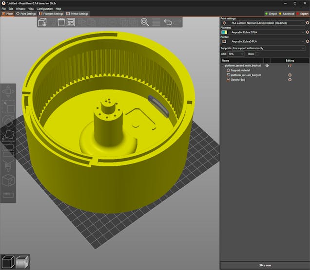
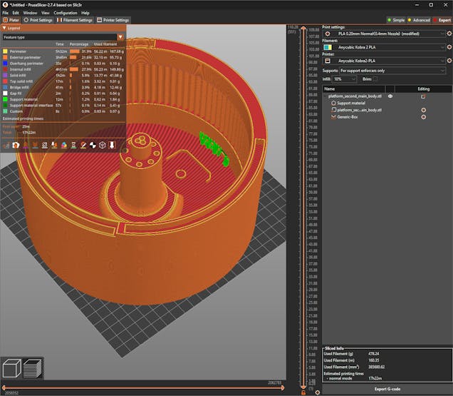
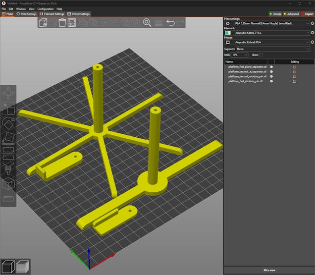
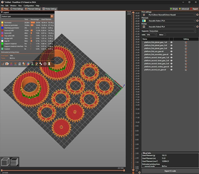
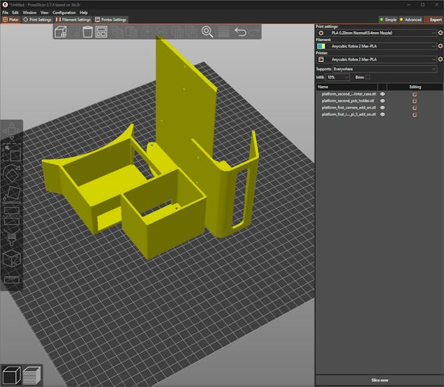
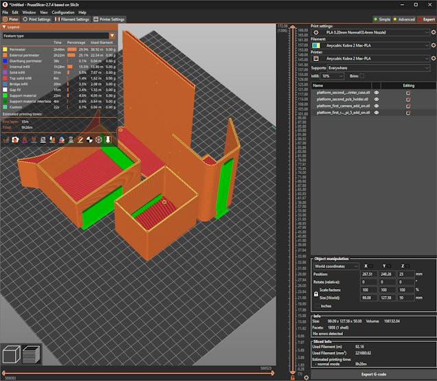
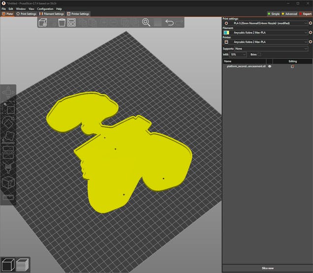
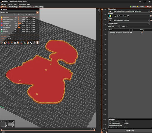
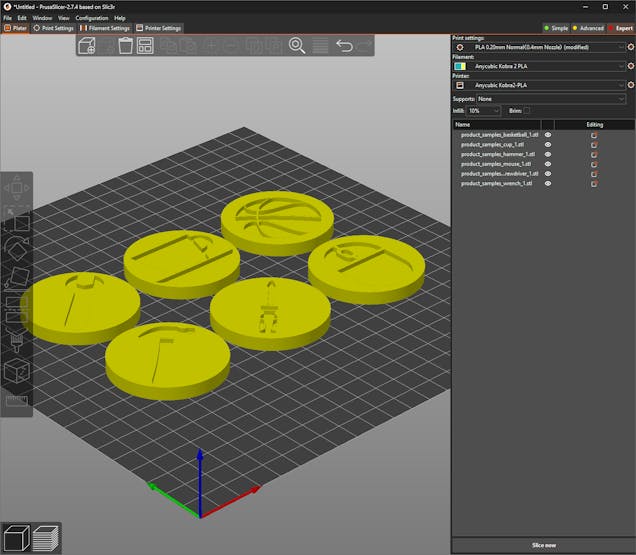
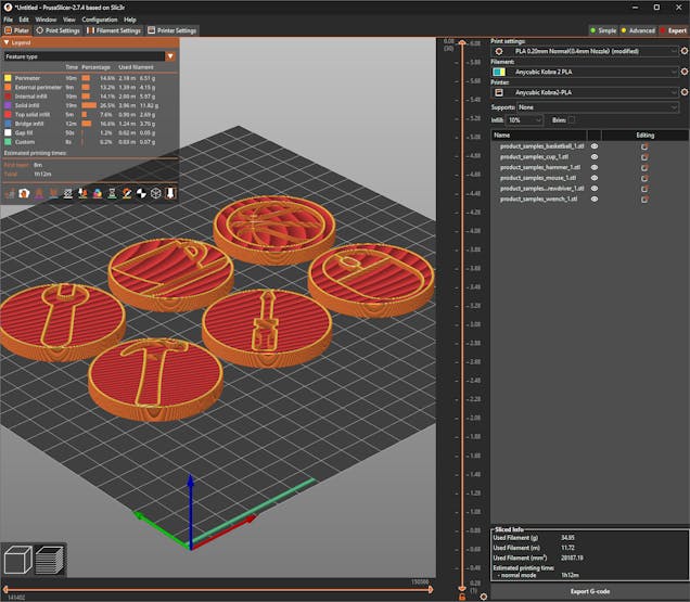
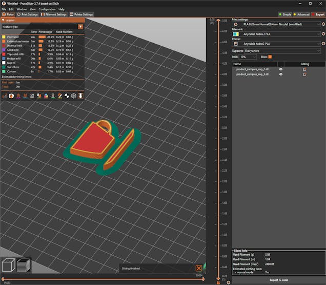
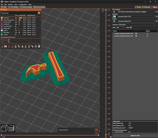
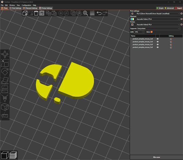
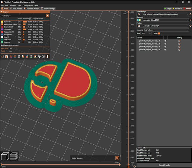
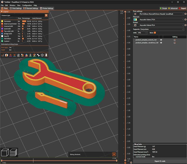
#️⃣ Then, I sliced the exported parts in PrusaSlicer, which provides lots of groundbreaking features such as paint-on supports and height range modifiers.
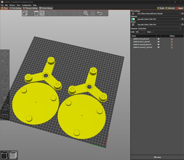
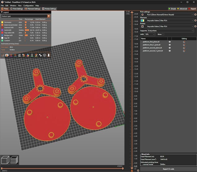
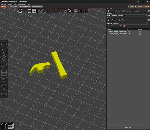
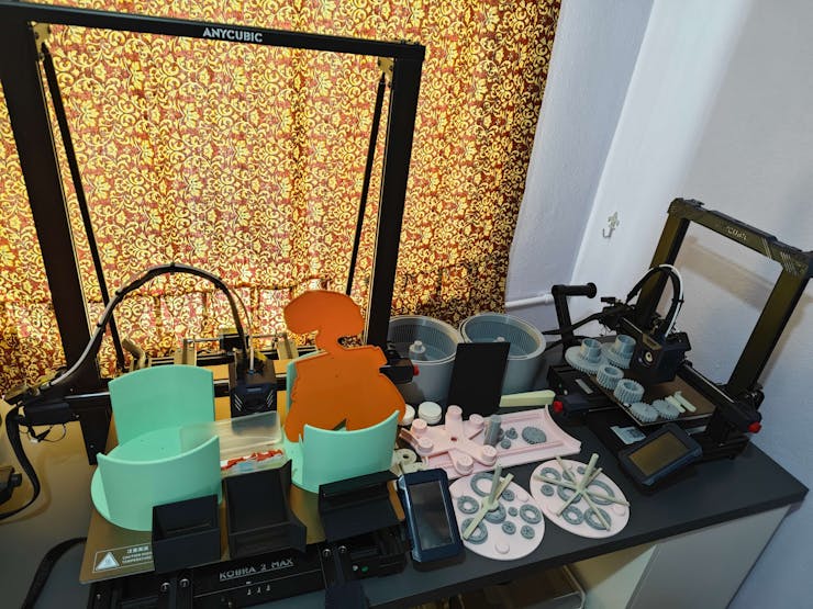
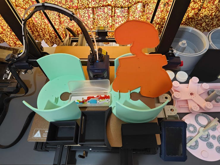
#️⃣ Due to the fluctuating part dimensions, I needed to utilize my Anycubic Kobra 2 and Kobra 2 Max 3D printers simultaneously while printing parts. Thus, I applied the relative slicer settings for each printer.
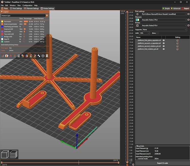
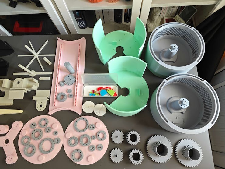
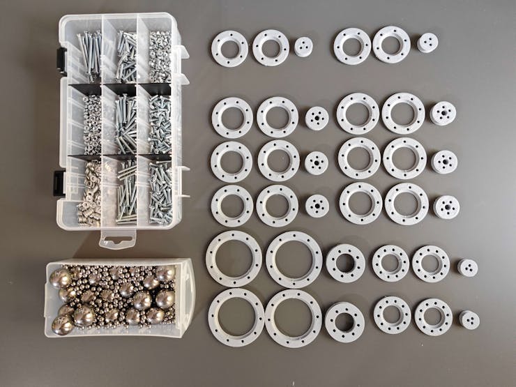
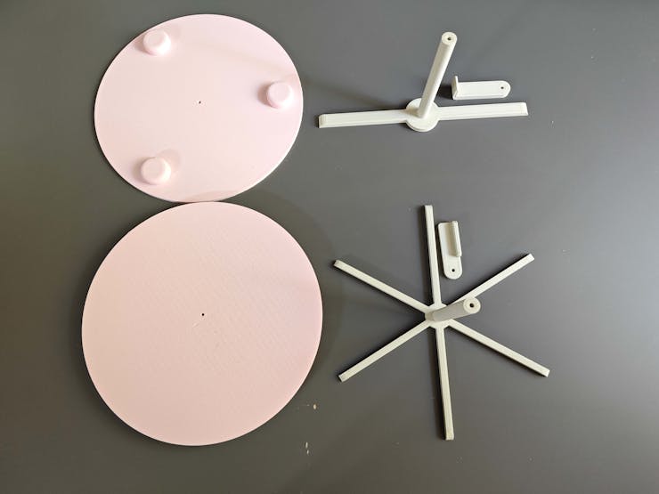
⚙️ Platforms:
![]()
![]()
![]()
![]()
![]()
![]()
![]()
![]()
![]()
![]()
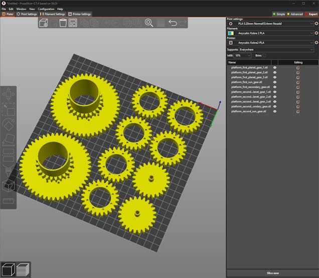
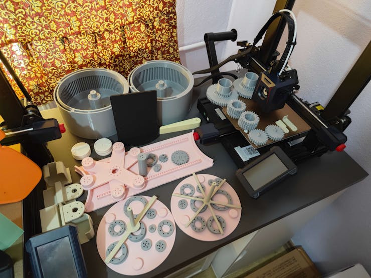
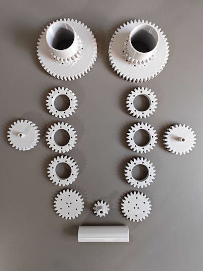
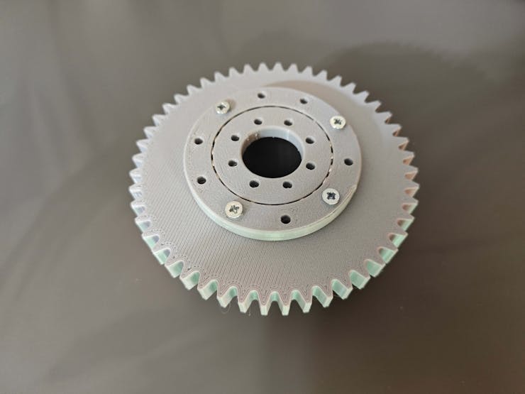
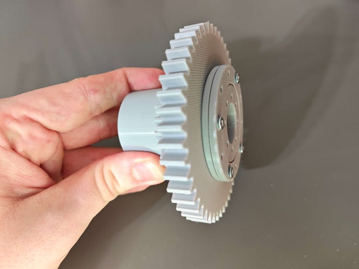
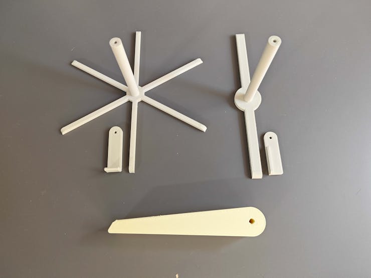
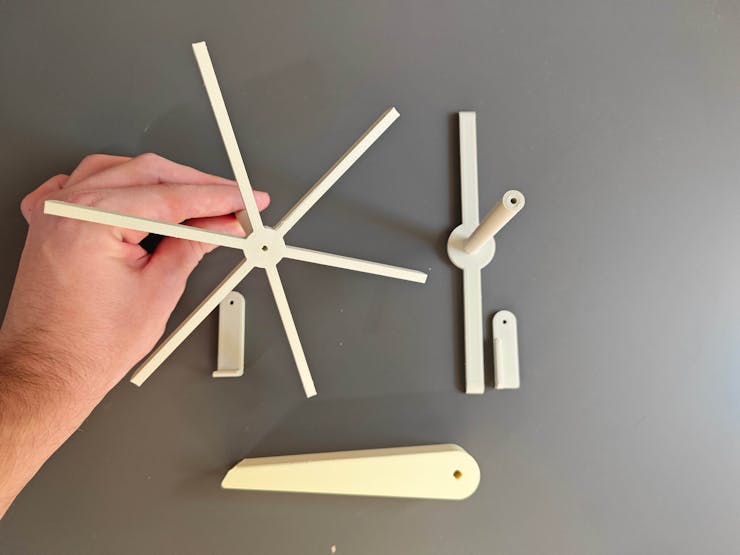
⚙️ Gears:
![]()
![]()
![]()
![]()
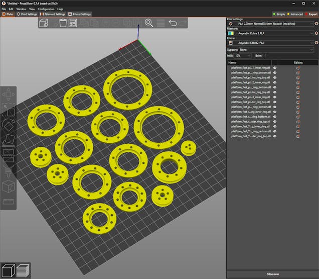
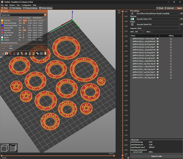
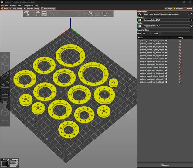
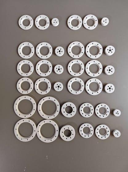
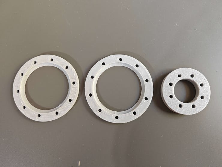
⚙️ Bearings:
![]()
![]()
![]()
![]()
⚙️ Transportation mechanism:
![]()
![]()
![]()
![]()
![]()
![]()
⚙️ Accessories:
![]()
![]()
![]()
![]()
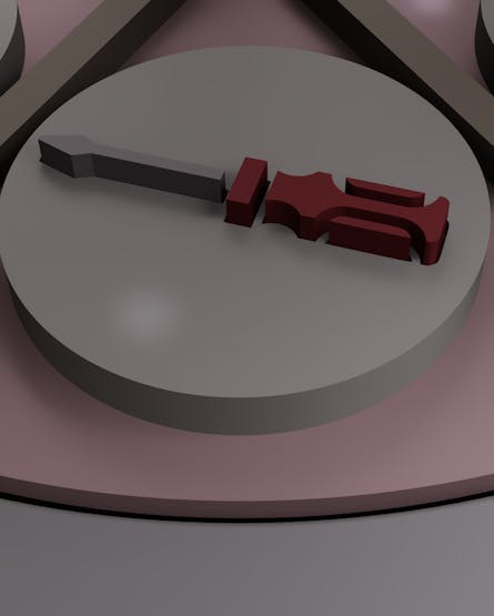
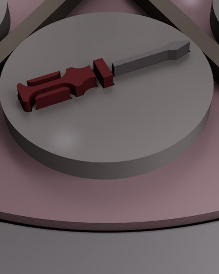
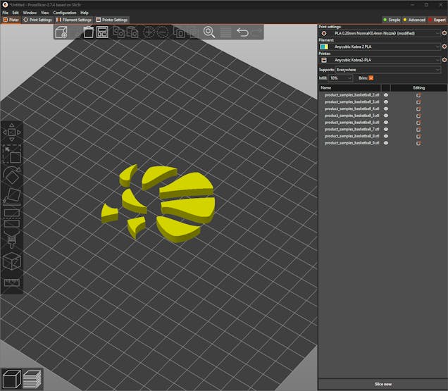
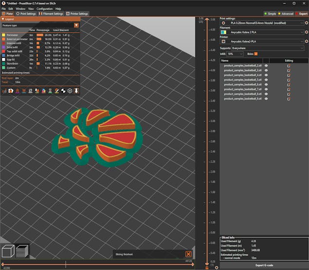
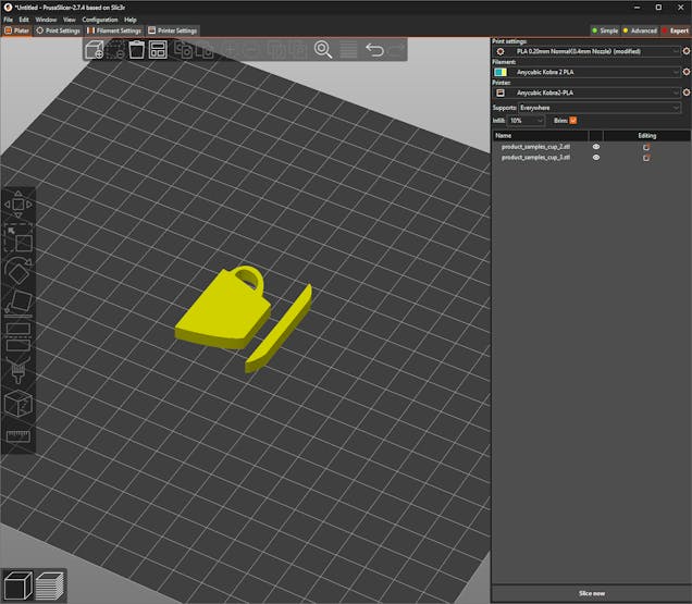
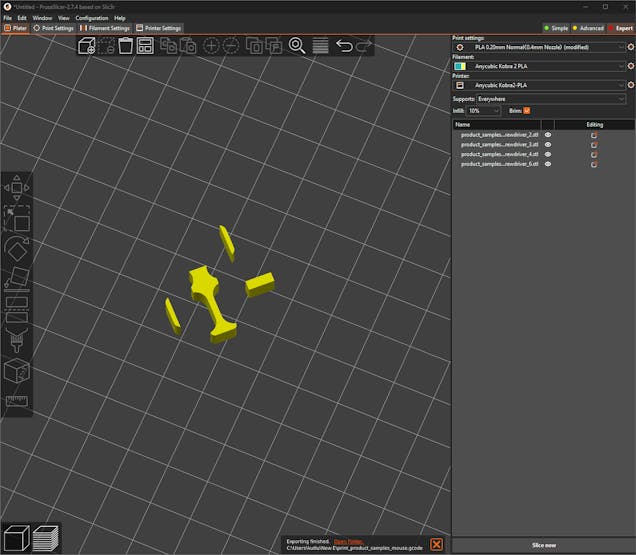
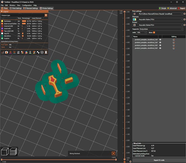
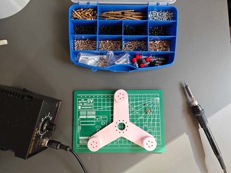
⚙️ Sample products:
![]()
![]()
![]()
![]()
![]()
![]()
![]()
![]()
![]()
![]()
![]()
![]()
![]()
![]()
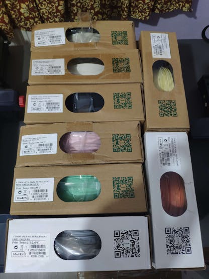
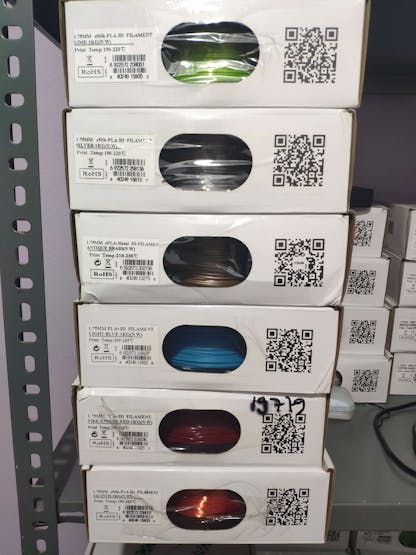
As mentioned earlier, I assigned PLA filament attributes for each virtual 3D part. I utilized the exact PLA filaments to print their real-world counterparts.
![]()
![]()
![]()
![]()
![]()
![]()
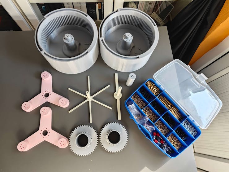
After printing all 3D parts successfully, I started to work on assembling the real-world shipping workstation.
![]()
![]()
![]()
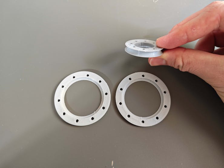
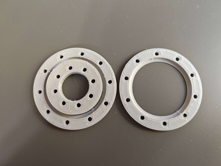
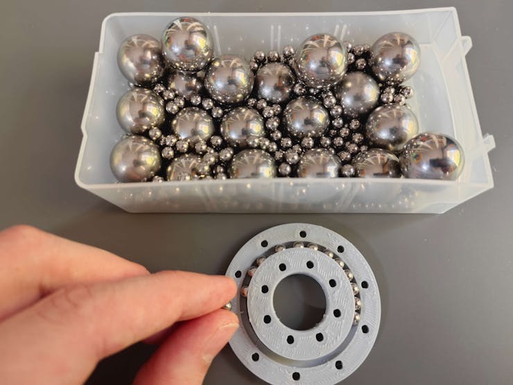
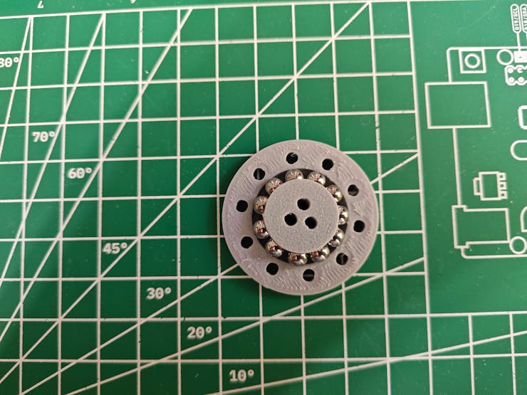
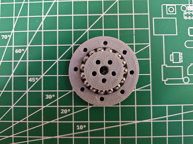
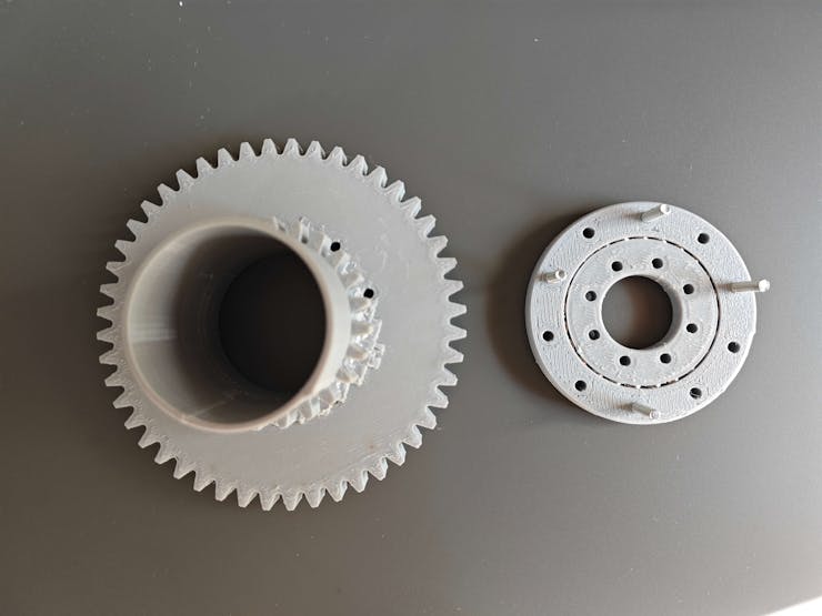
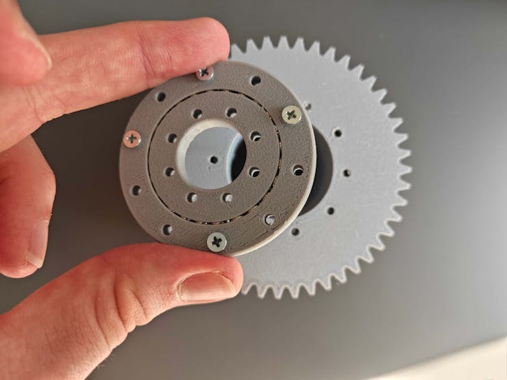
#️⃣ First, I assembled all custom ball bearings.
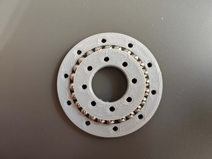
#️⃣ To assemble one of my custom bearings, place the required number of 5 mm steel balls between the inner ring and the bottom outer ring.
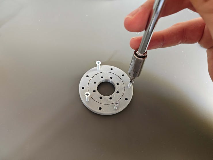
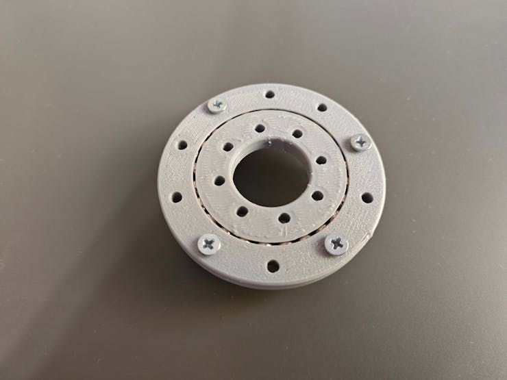
#️⃣ Then, cap the placed steel balls with the top outer ring and utilize M3 screws to adjust the bearing tightness.
![]()
![]()
![]()
![]()
![]()
![]()
![]()
![]()
![]()
![]()
![]()
![]()
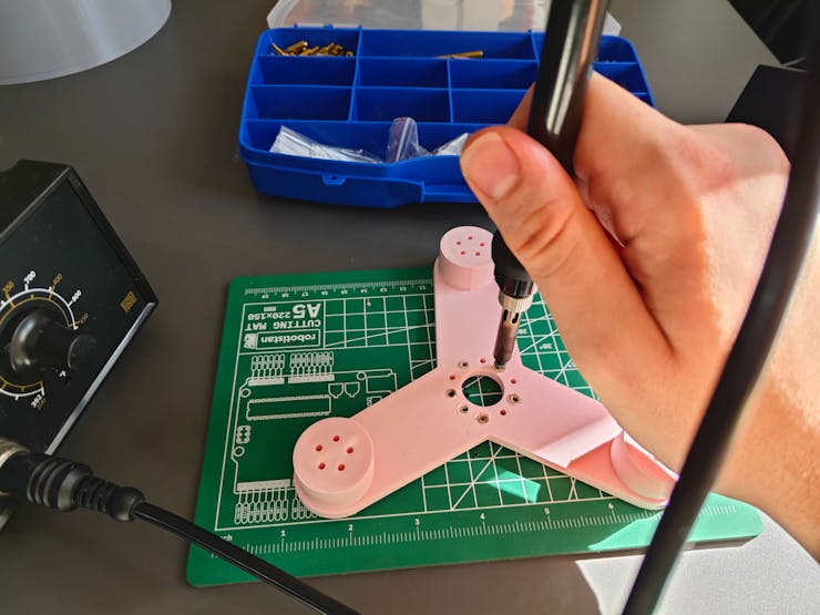
❗ Although all related 3D parts can be affixed via M3 screws after printing, plastic parts tend to loosen or break after a while due to friction and abrasion. Thus, I employed a well-known injection molding technique to make some connections more sturdy — M3 brass threaded inserts.
![]()
![]()
![]()
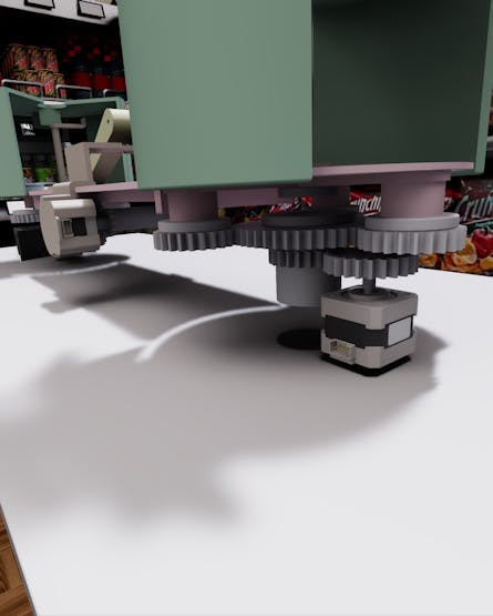
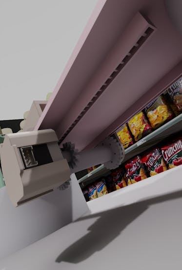
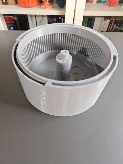
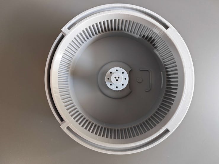
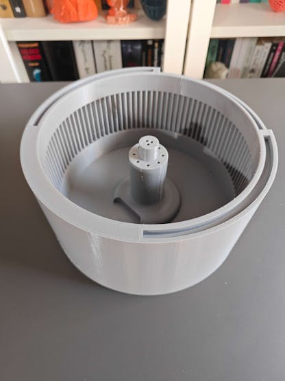
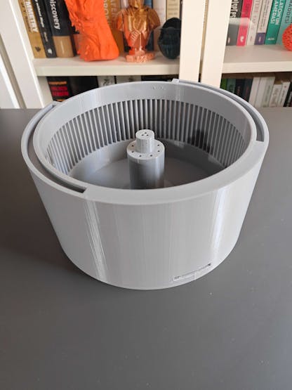
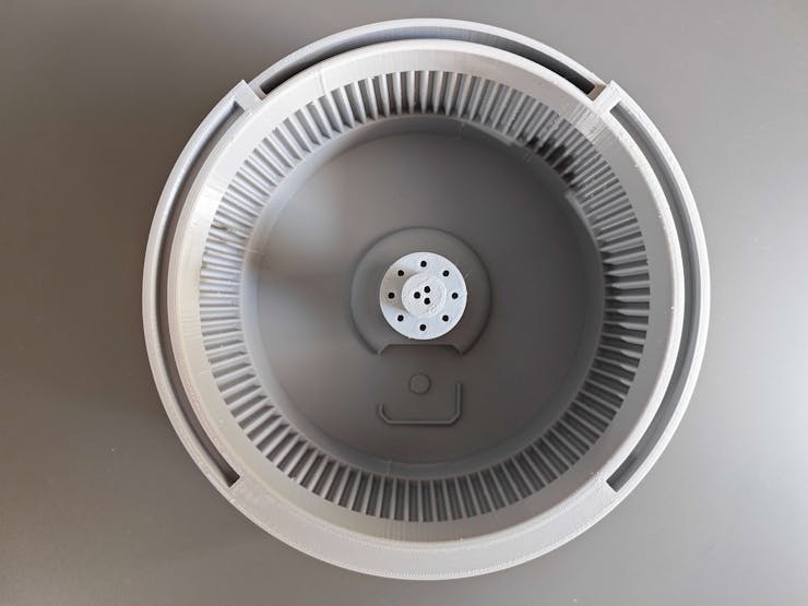
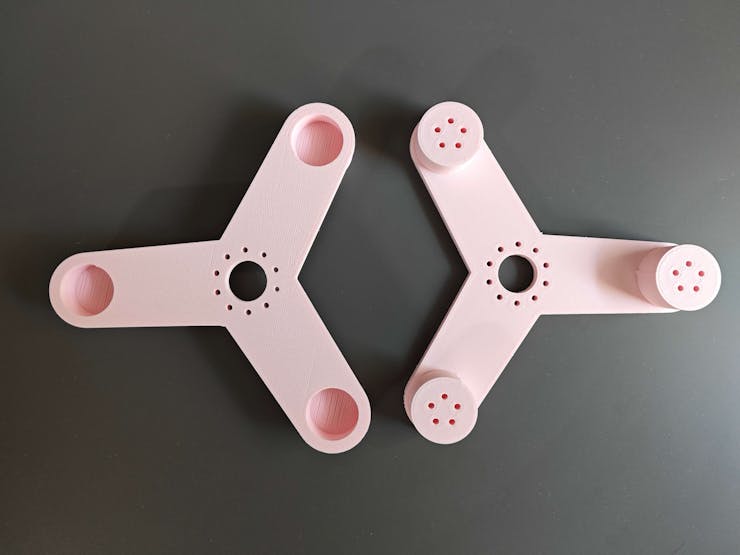
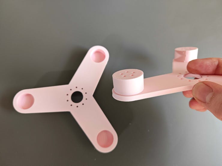
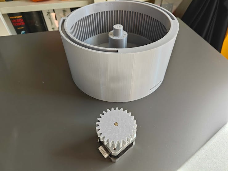
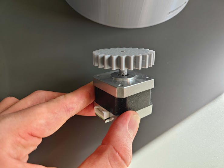
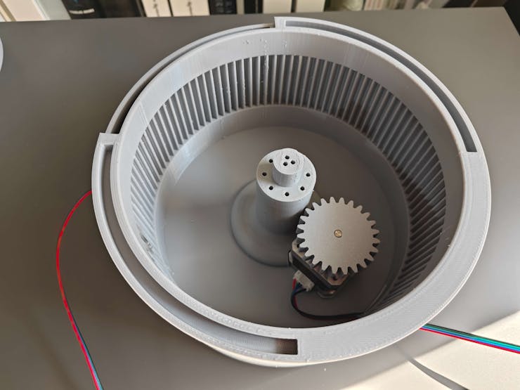
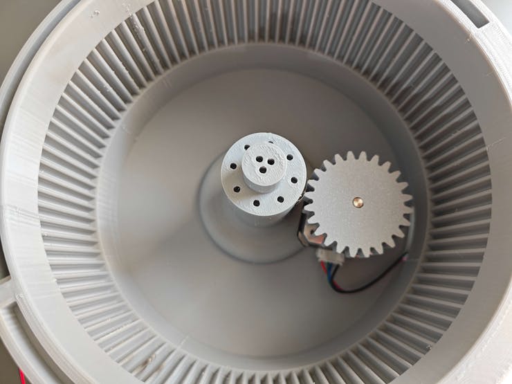
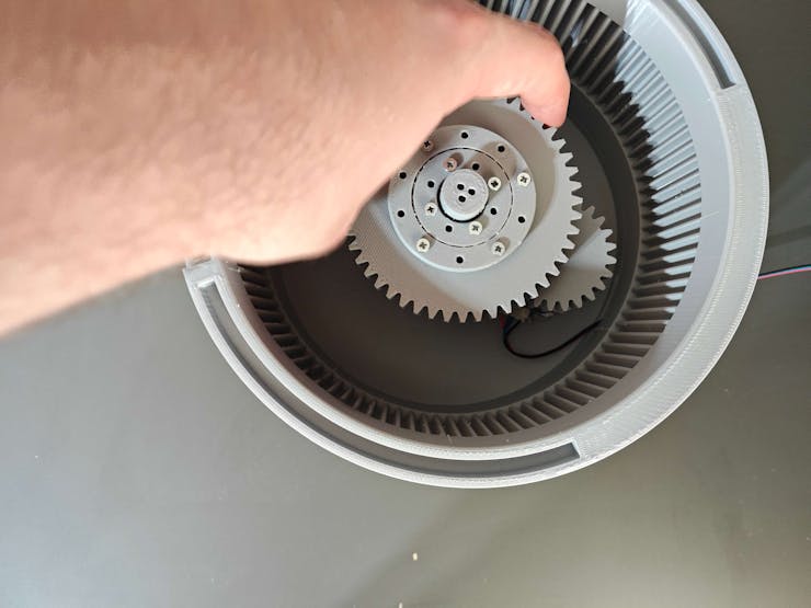
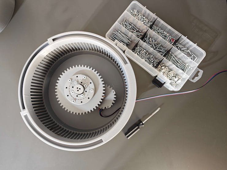
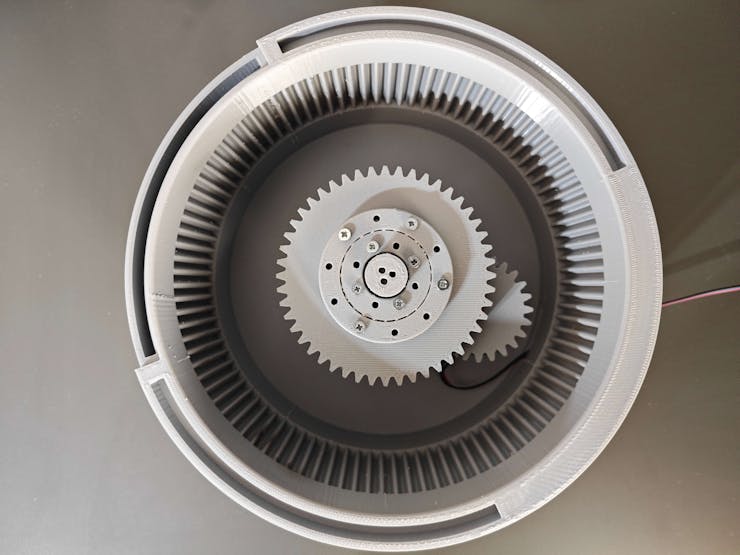
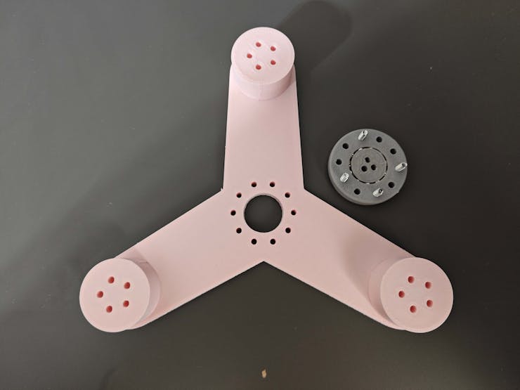
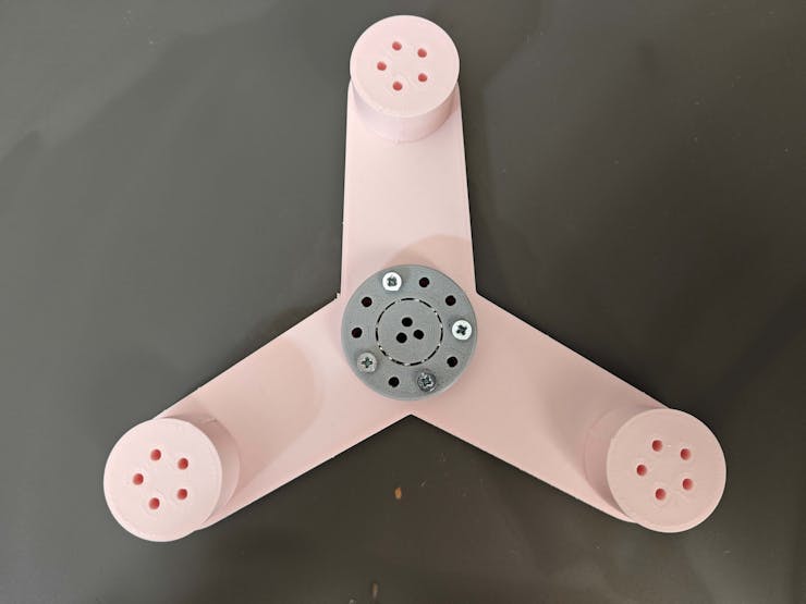
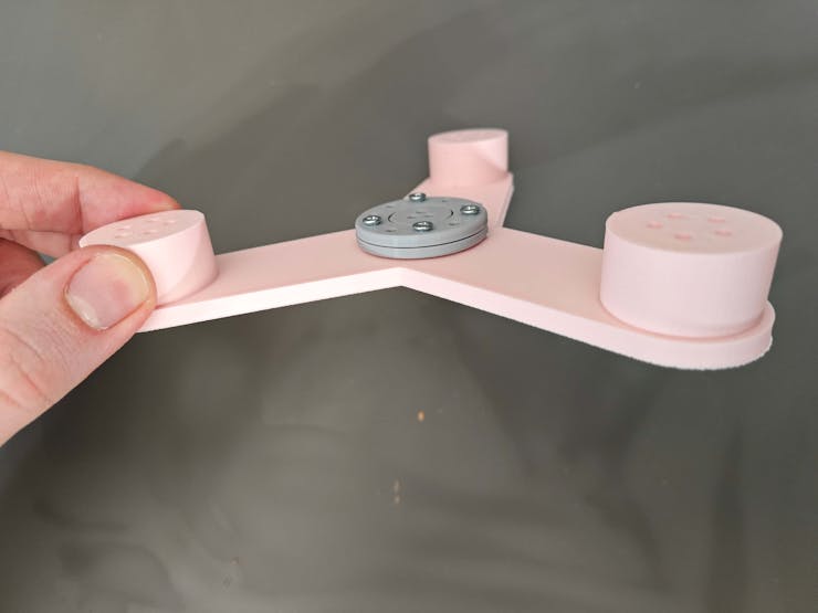
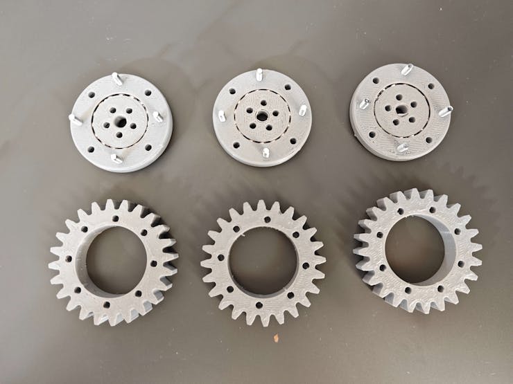
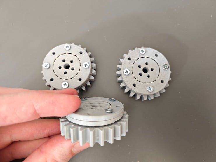
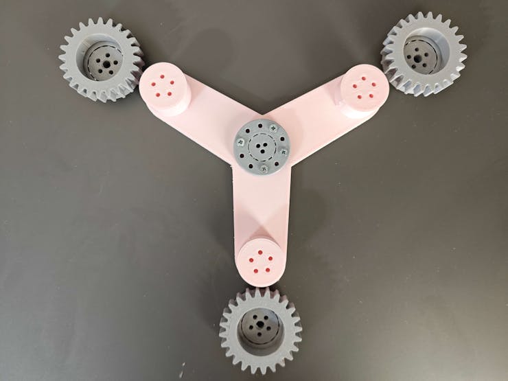
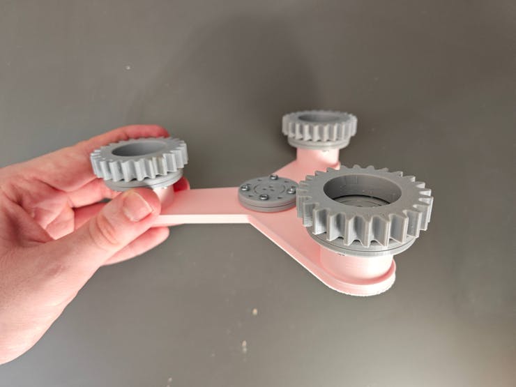
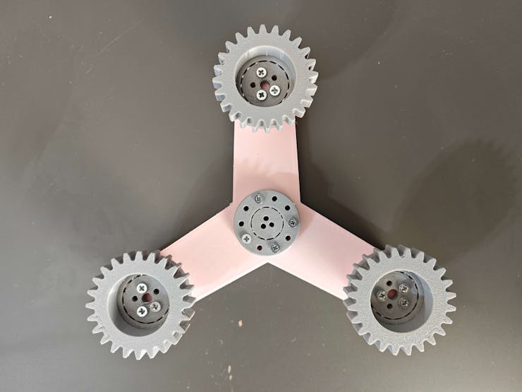
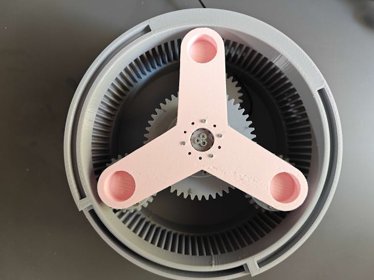
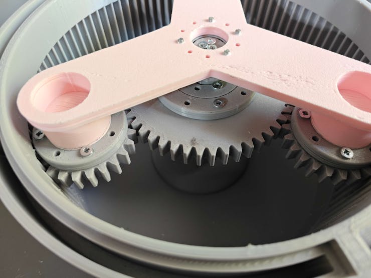
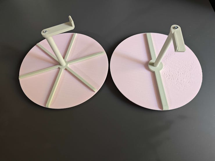
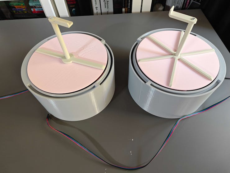
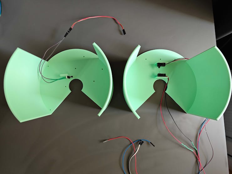
#️⃣ For each rotating platform, I fastened the required Nema 17 stepper motor and assembled the planetary gear mechanism consisting of a sun gear, three planet gears, a secondary stepper motor gear, and a Y-shaped planet carrier.
#️⃣ As explained earlier, I employed custom bearings to connect swiveling components to maintain stable torque distribution.
![]()
![]()
![]()
![]()
![]()
![]()
![]()
![]()
![]()
![]()
![]()
![]()
![]()
![]()
![]()
![]()
![]()
![]()
![]()
![]()
![]()
![]()
![]()
![]()
![]()
![]()
![]()
![]()
![]()
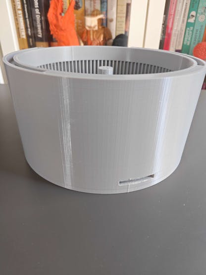
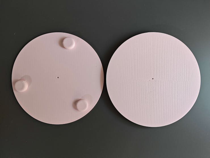
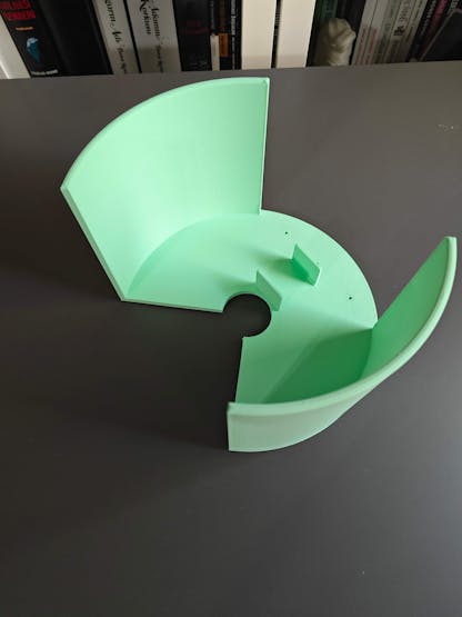
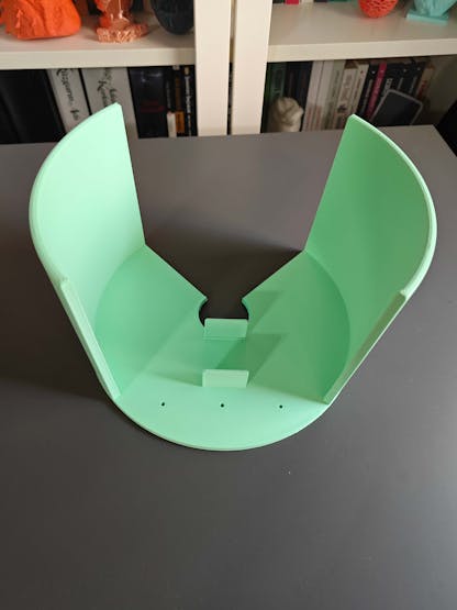
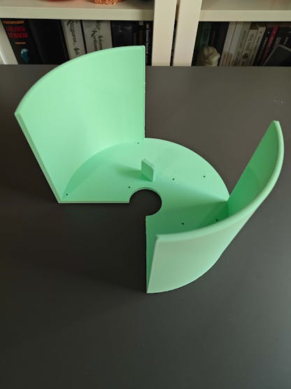
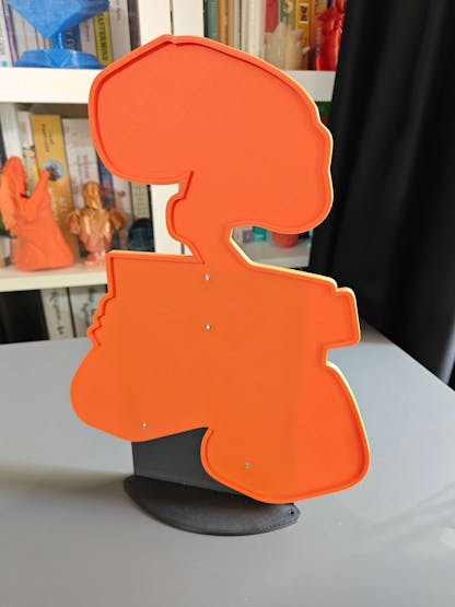
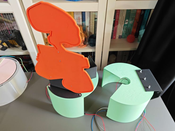
#️⃣ After completing the planetary gear mechanisms, I assembled the platform faces, face separators, and rotation pins respectively via M3 screws.
![]()
![]()
![]()
![]()
![]()
![]()
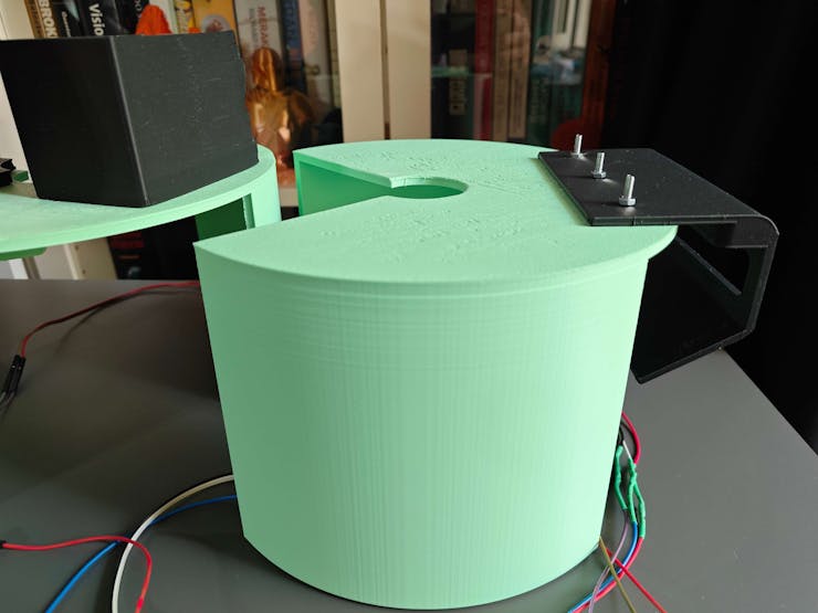
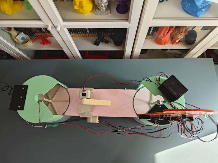
#️⃣ Then, I checked the straightness of the transportation road, bridging the first platform with the second platform.
![]()
![]()
![]()
![]()
#️⃣ I fastened the required Nema 17 stepper motors and assembled the transportation carrier consisting of two pinions, a pinion connection pin, a stepper motor direction gear, and a basic carrier arm.
#️⃣ As explained earlier, I employed custom bearings to connect swiveling components to maintain stable torque distribution.
#️⃣ Since the rack and pinion system has close-fitting components, I adjusted the tension of the M3 screws connecting the carrier components to reduce friction and stress.
#️⃣ After attaching the carrier arm, I fastened the micro switch via the hot glue gun to the left side of the transportation road, required for the automated homing sequence.
![]()
![]()
![]()
![]()
![]()
![]()
![]()
![]()
![]()
![]()
![]()
![]()
![]()
![]()
![]()
![]()
![]()
![]()
![]()
![]()
![]()
![]()
![]()
![]()
![]()
![]()
![]()
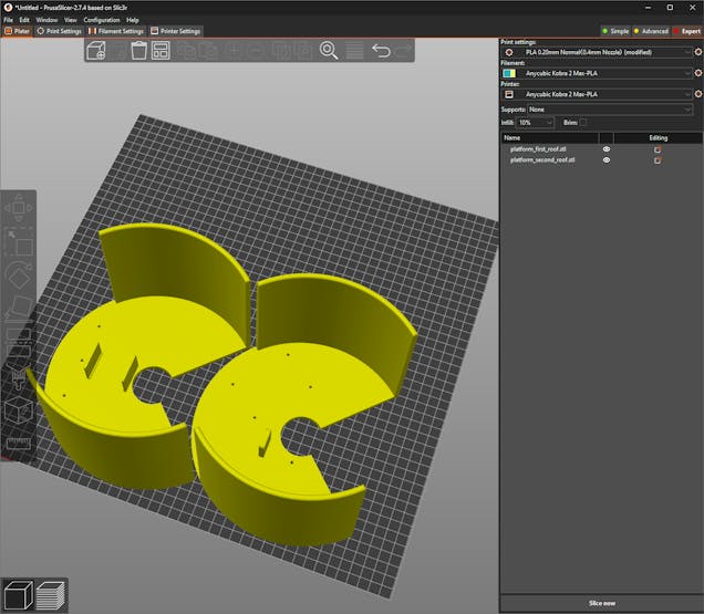
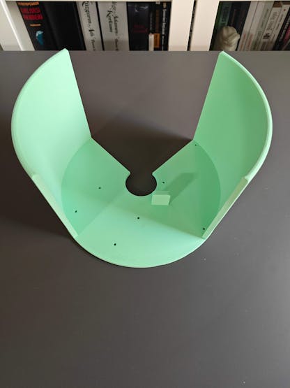
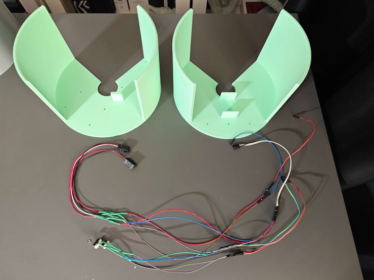
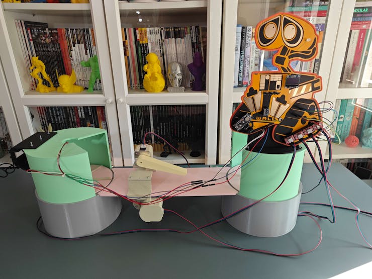
#️⃣ After completing the product transportation system, I assembled the platform roofs with their corresponding accessories.
#️⃣ As the selected homing methods, I fastened the IR break-beam sensor (receiver and transmitter) to the first platform roof and the micro switch to the second platform roof.
![]()
![]()
![]()
![]()
![]()
![]()
![]()
![]()
![]()
![]()
![]()
![]()
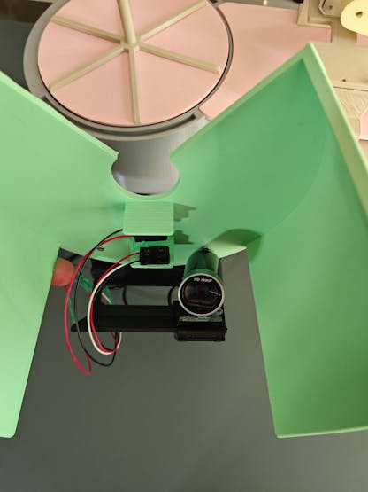
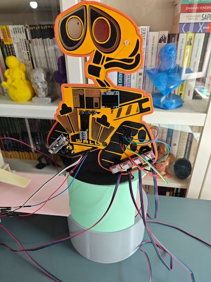
#️⃣ As I completed assembling all shipping workstation 3D parts, I attached Raspberry Pi 5, the USB webcam, and the tiny thermal printer to their corresponding add-ons.
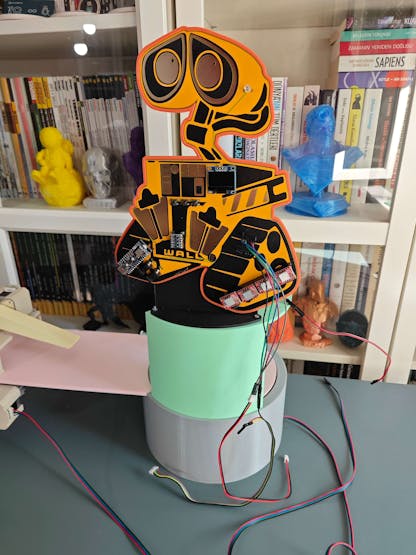
#️⃣ Then, I fastened the Wall-E PCB to its encasement and finished all remaining PCB wiring, including the ATX adapter board 5V and 12V power outputs.
![]()
![]()
![]()
![]()
![]()
![]()
![]()
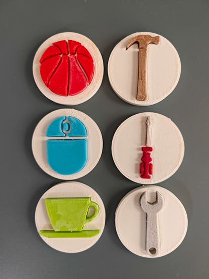
#️⃣ After affixing the Wall-E PCB successfully, I assembled all enamel pin-inspired sample products representing various objects by utilizing super glue.
![]()
![]()
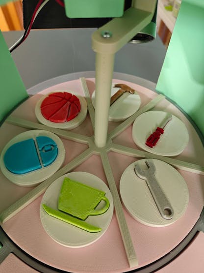
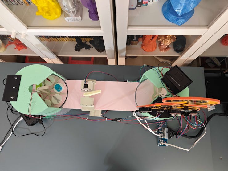
#️⃣ Then, I placed all sample products into their corresponding compartments on the first rotating platform, sectioned by the first face separator.
![]()
![]()
![]()
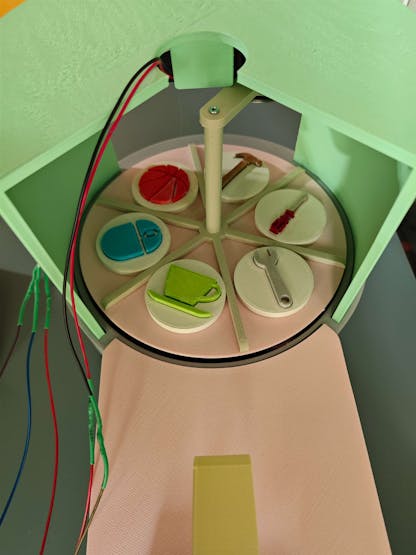
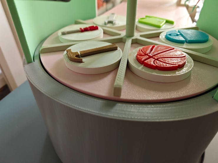
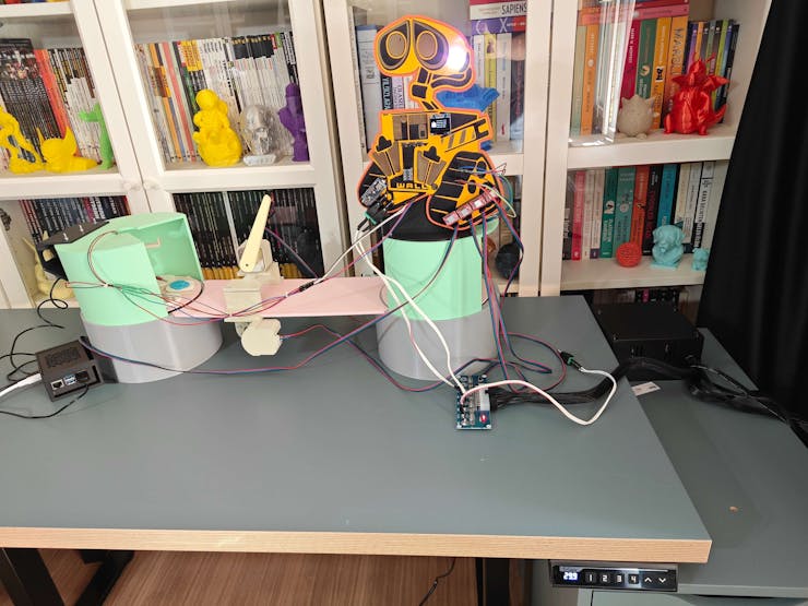
#️⃣ After preparing the enamel pin-inspired sample products, I rigorously analyzed the moving parts of the real-world shipping workstation to detect mechanical aberrations.
![]()
![]()
![]()
![]()
![]()
❗ After a while, I noticed the first iteration of the carrier arm with 35% infill engendered tension issues, resulting in sudden torque fluctuations. Thus, I printed the second iteration by reducing the carrier arm size and infill (12%).
![]()
-
20Step 8.0: Setting up Arduino Nano Matter on Arduino IDE
Before proceeding with programming Arduino Nano Matter, I needed to configure the required board settings and install the associated component libraries.
Since Nano Matter is a state-of-the-art IoT development board with the powerful MGM240S wireless module from Silicon Labs providing versatile connectivity options, enabling Matter IoT protocol and Bluetooth® Low Energy, it requires Arduino IDE 2.0+ or Arduino Cloud Editor to be programmed.
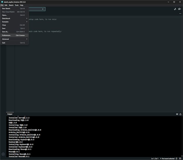
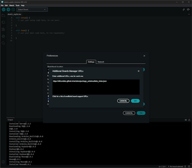
#️⃣ To enable the Silicon Labs core, go to File ➡ Preferences ➡ Additional boards manager URLs and add the official board package URL:
https://siliconlabs.github.io/arduino/package_arduinosilabs_index.json
![]()
![]()
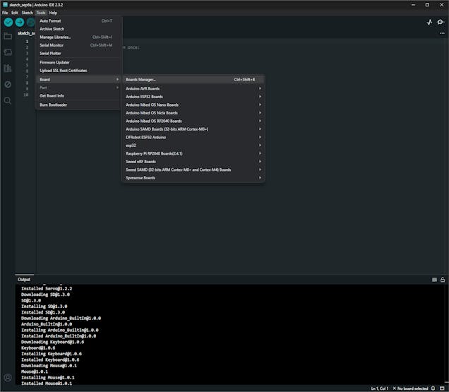
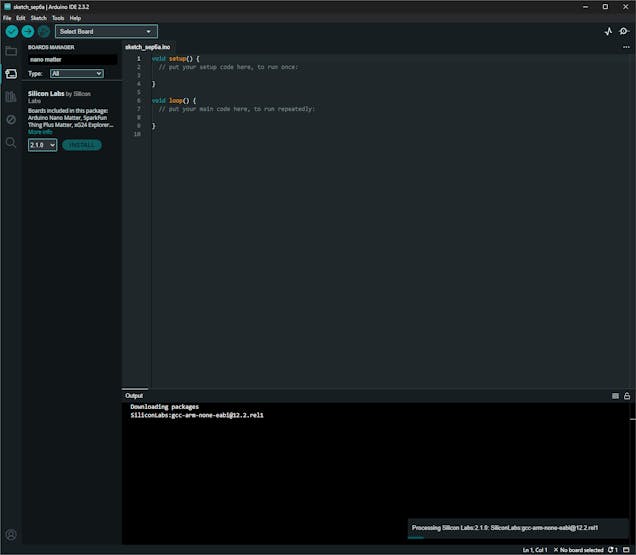
#️⃣ To install the required board core, navigate to Tools ➡ Board ➡ Boards Manager, search for Nano Matter, and download the latest version.
![]()
![]()
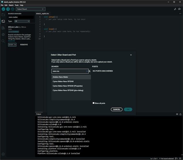
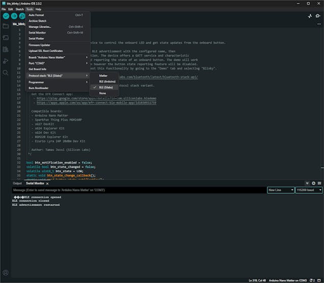
#️⃣ After installing the core successfully, choose Arduino Nano Matter to upload sketches. Then, navigate to Tools ➡ Protocol stack and select BLE (Silabs) to utilize the accurate configurations for establishing BLE connections.
![]()
![]()
#️⃣ After setting up Nano Matter, I installed the libraries required to control the attached electronic components:
Adafruit-Thermal-Printer-Library | Download
Adafruit_SSD1306 | Download
Adafruit-GFX-Library | Download
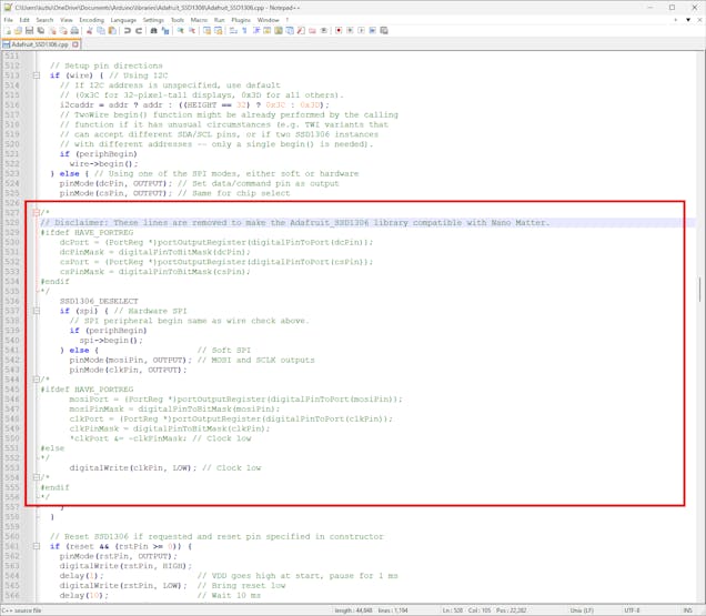
❗ As I started to program Nano Matter, the Arduino IDE threw some errors regarding the Adafruit SSD1306 library due to the functions incompatible with the Silicon Labs core, including but not limited to digitalPinToInterrupt and portOutputRegister. To solve these compiling issues, I modified the Adafruit_SSD1306.cpp file by removing the highlighted lines below.
![]()
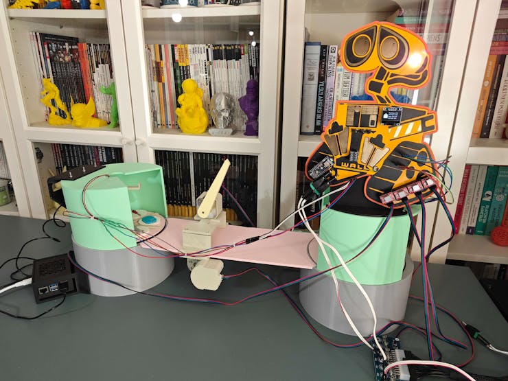
Digital twin-enabled Smart Shipping Workstation
Exploring the digital twin synthetic data generation and AI-oriented advancements on real-world shipping operations with NVIDIA Omniverse.


Discussions
Become a Hackaday.io Member
Create an account to leave a comment. Already have an account? Log In.