-
1Step 1
3D print all the pieces. I used PLA for stiffness. All my 3D models were designed to be printed without the need for any support structures. You will need a 3D printer with a minimum print volume of 220mm x 220mm x 120mm in order to print these files.
I should note that I actually designed and printed these parts *before* receiving the actual parts like the LCD screen, controller, speaker, amplifier etc. 3D printing takes quite a lot of time and I didn't want to wait till everything I ordered has arrived in the mail before I started printing. So, some of the parts were designed with some flexibility in terms of how it would be laid out. Also, this was a learning process for me as I am still relatively new to 3D printing, so some parts have gone through many changes as I experimented with the design. I believe all the files I uploaded should be correct, but in case there are any mistakes, do let me know.
Please understand that I am sharing these files AS IS. You do need to have a decent knowledge of 3D printing, Raspberry Pi, soldering, etc. in order to put it all together. Any information that I did not include here, you will be able to Google it.
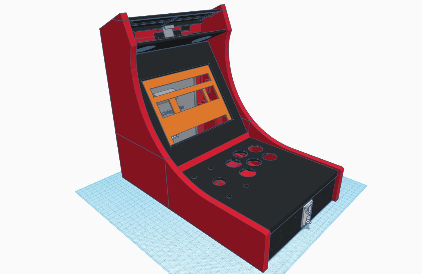
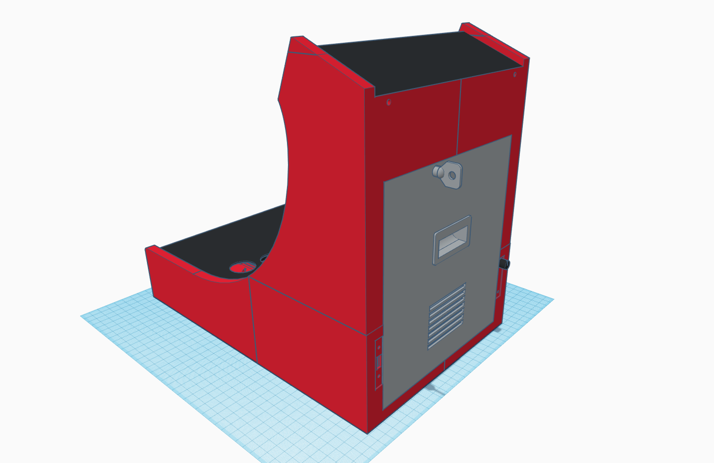
Here are reference photos to give you a better idea of how all the pieces fit together.
![]()
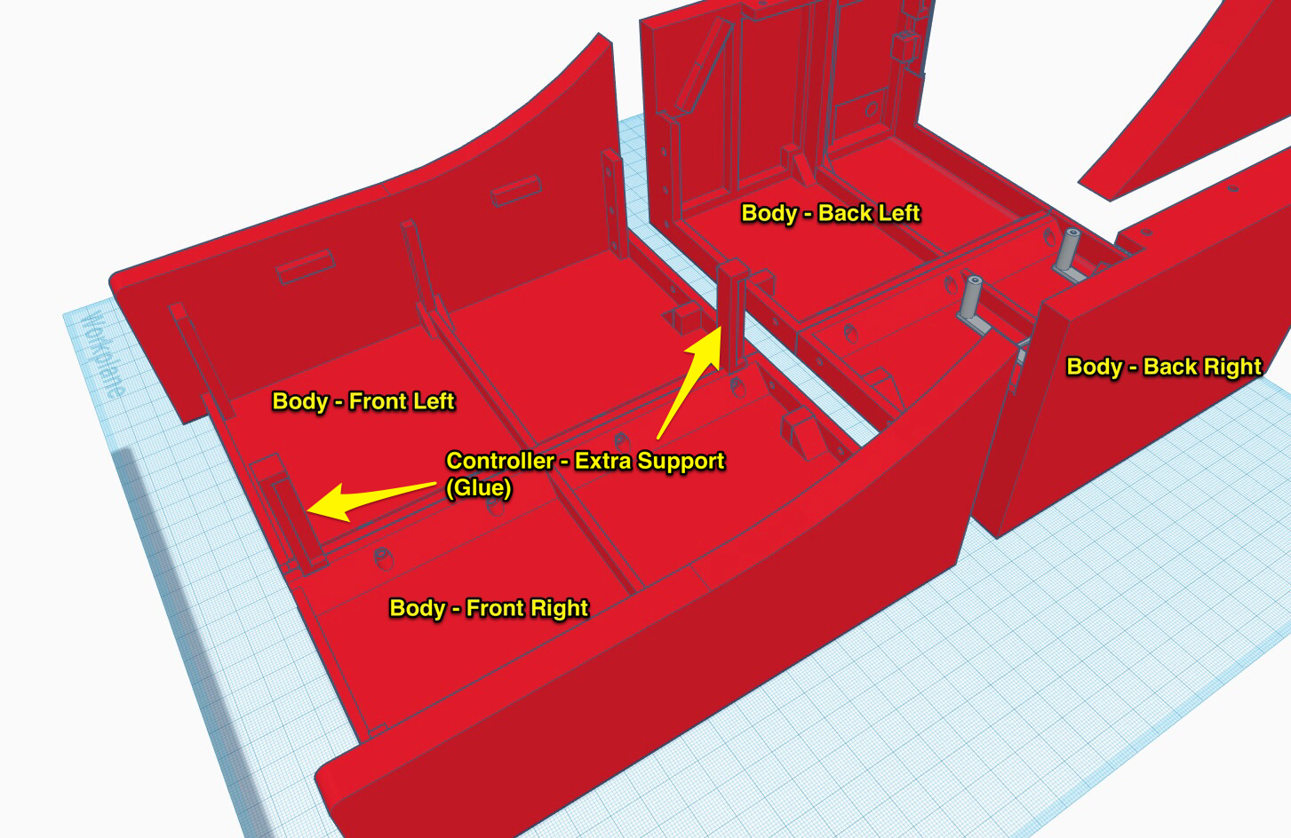
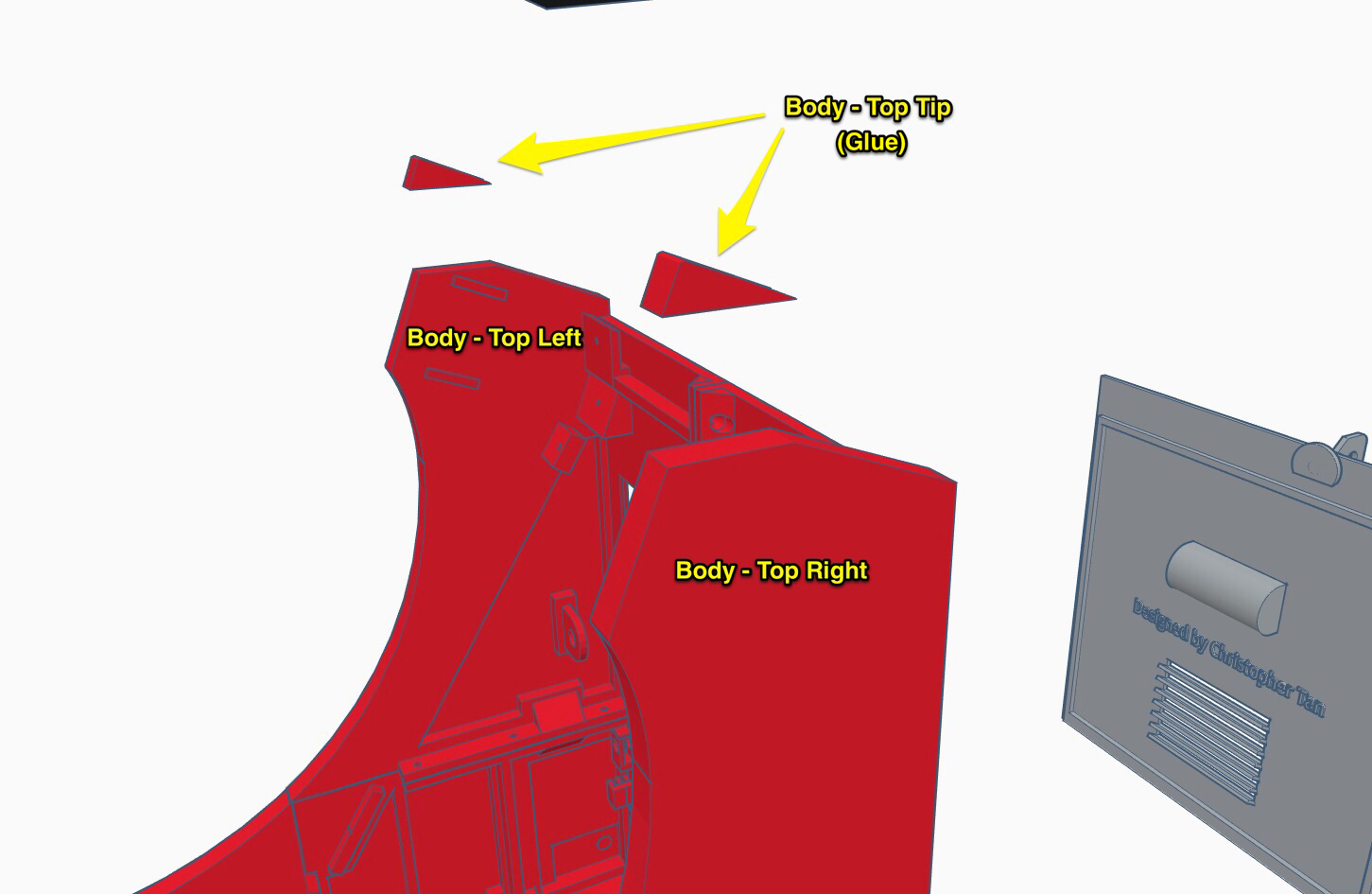
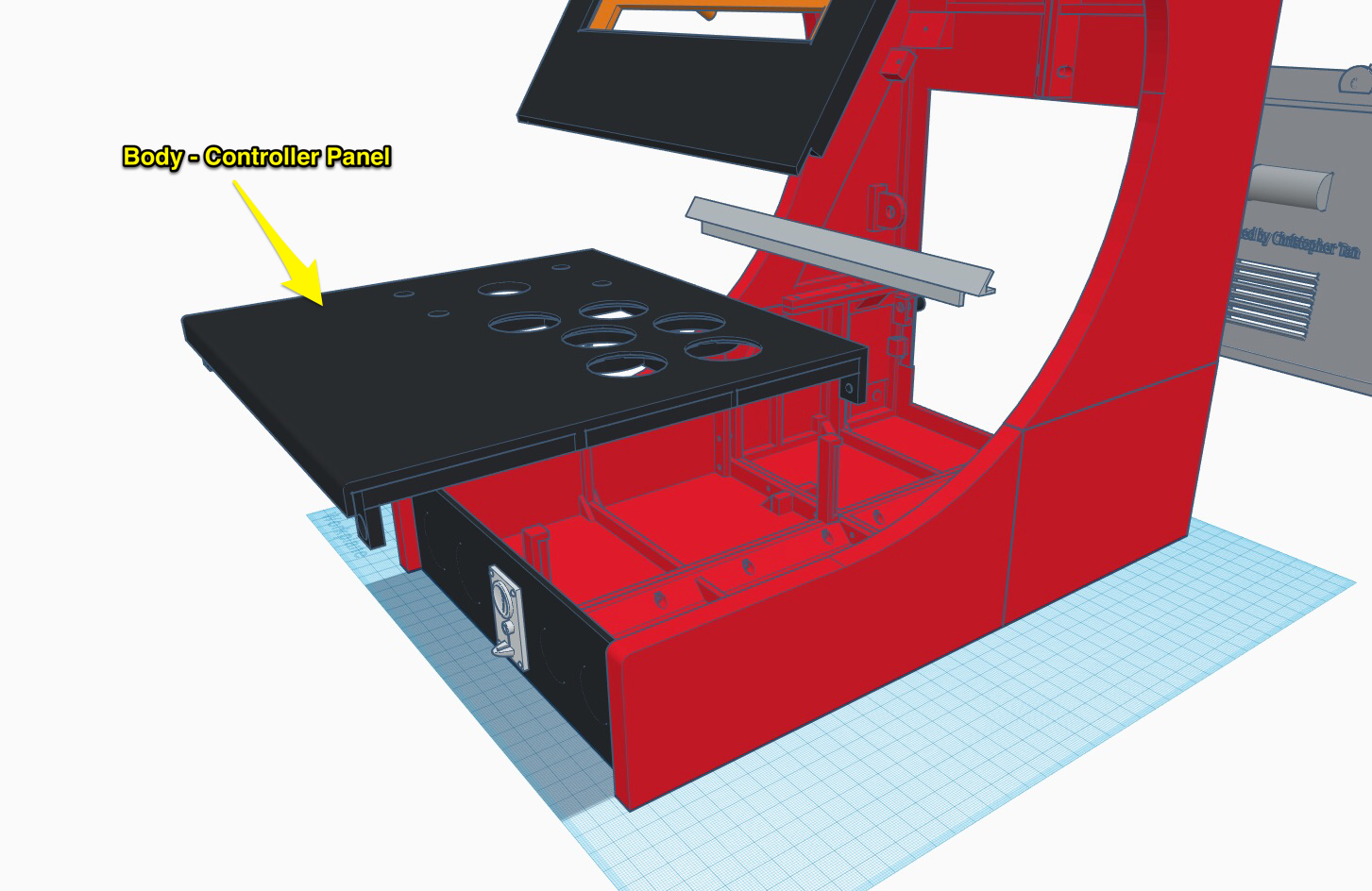
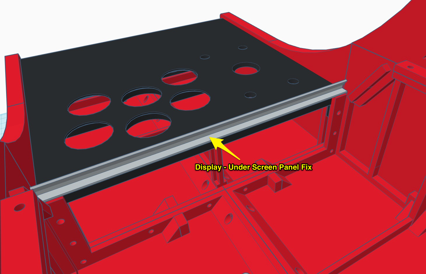
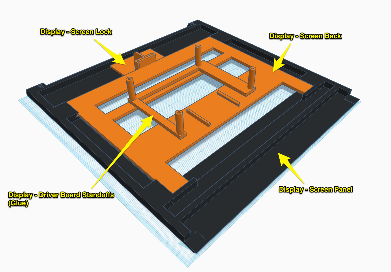
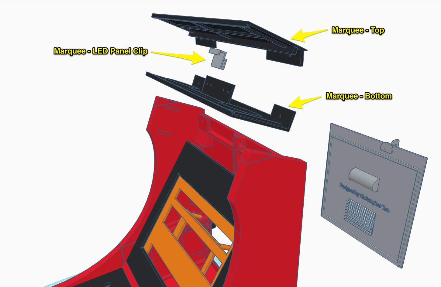
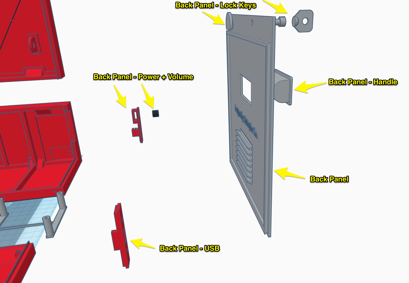
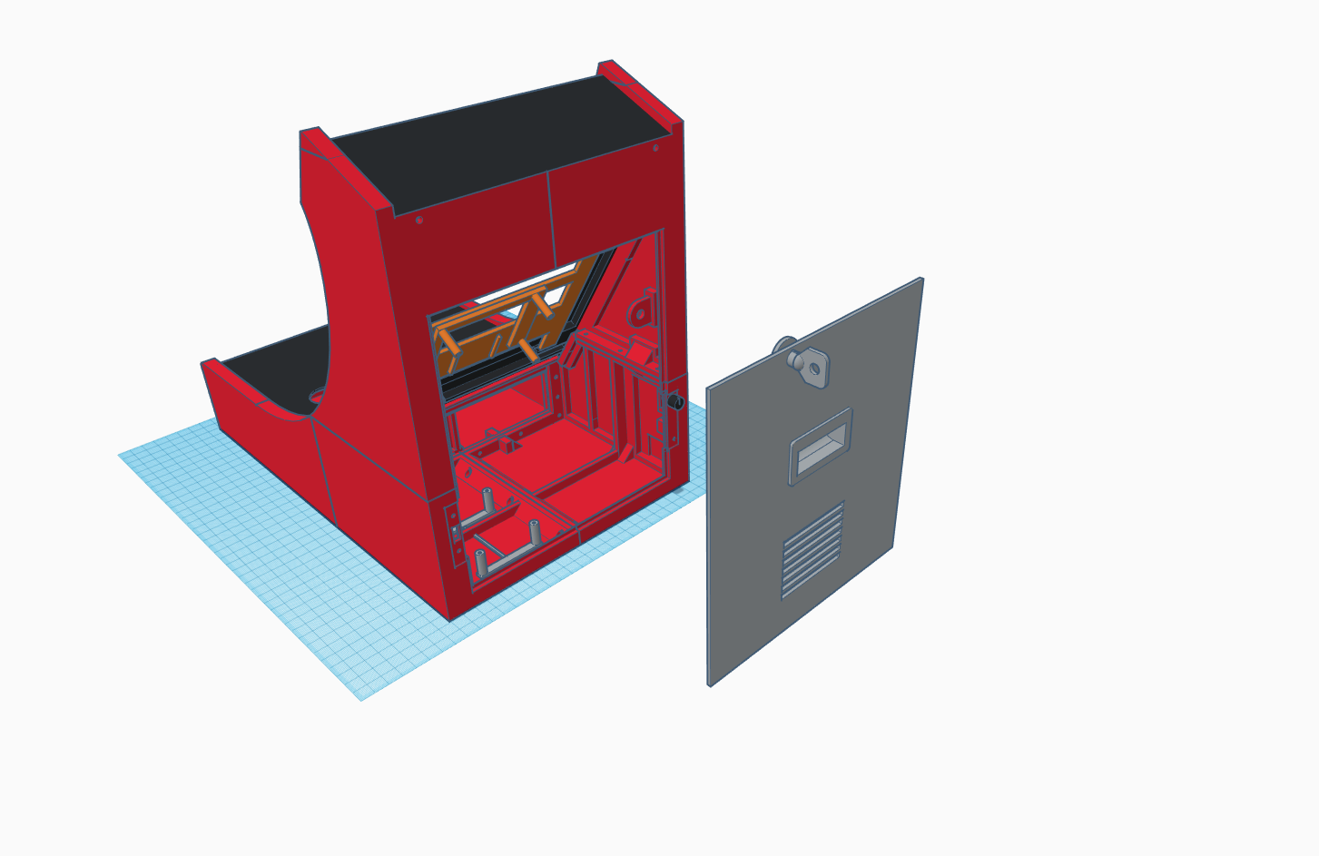
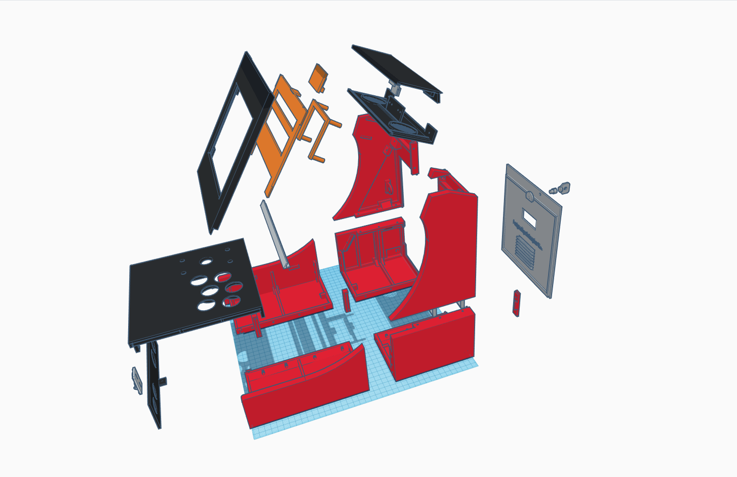
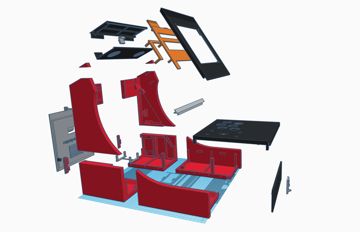
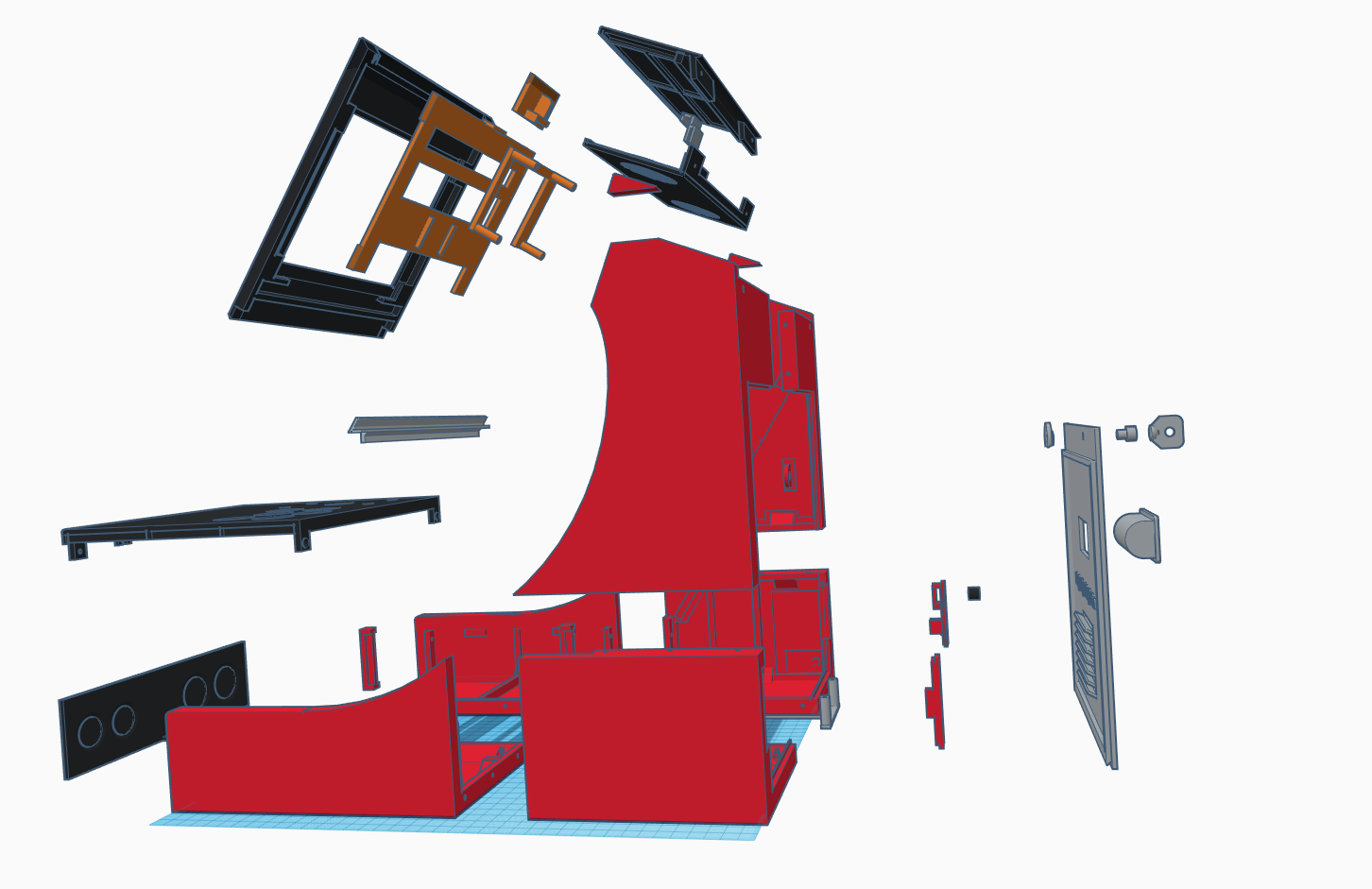
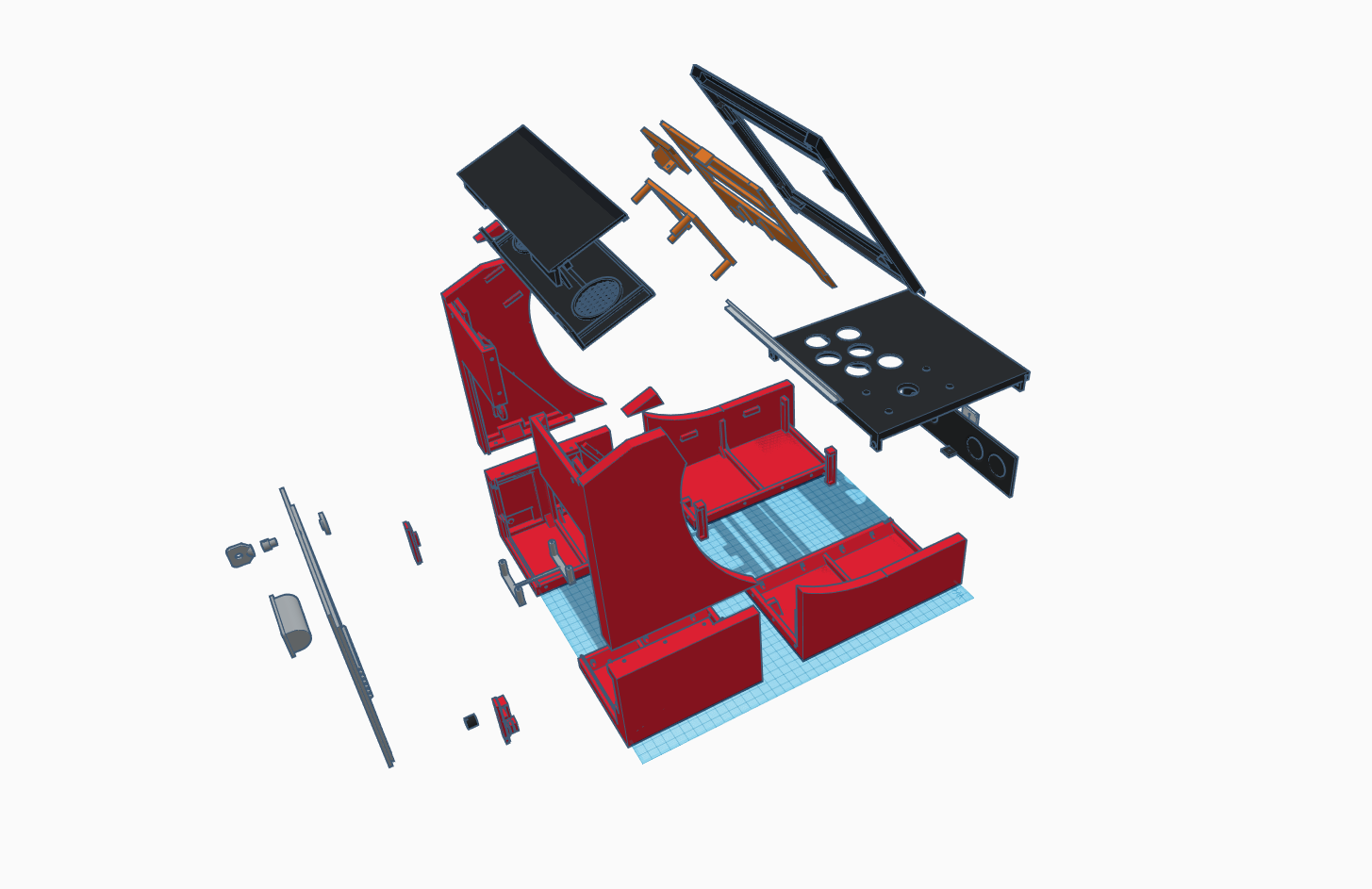
Here are exploded views to give you a general overview of where everything is positioned.
![]()
![]()
![]()
![]()
And here are the completely assembled views.
![]()
![]()
Most of the main pieces are held together using nuts and bolts, or screws. You will need M3 bolts of various lengths (probably 10mm - 16mm) and some screws. I am afraid I lost the specs of the screw I used, but it's about 10mm long and 2.5mm diameter. These were use for the marquee pieces.
I sprayed primer putty and sanded it down to a smooth finish before spraying matte black paint for the final finish. You want to make sure you sand the top edges of "Body - Front Left" and "Body - Front Right" so that they are nice and smooth, cause otherwise, when you rest your hands on them, the sharp edges will get irritating quite quickly.
In order to make it look like a commercial quality product, I did a lot of research into the designs of the artwork for old arcade machines. I took inspiration from them to create my own artwork for my arcade machine and had it commercially printed on vinyl stickers.
Connecting Everything Together
- The controller's USB connector will plug into the Raspberry Pi's USB socket.
- The power connecter for the display will plug into the Raspberry Pi's USB socket.
- The HDMI out on the Raspberry Pi needs to be connected to the HDMI input on the display controller board.
- The speaker needs to be soldered to the amplifier circuit, and the amplfier circuit's power input needs to the connected to the Raspberry Pi's GPIO pin 4 & 6 for the 5V power supply. You also need to solder an earphone jack connector to the amplifier circuit and plug that into the Raspberry Pi's audio socket.
- Solder together the LEDs and wire it to a USB connector. Plug it into the Raspberry Pi's USB socket.
So, everything is powered directly from the Raspberry Pi. The only cable going into the arcade machine is the Raspberry Pi's power supply cable.
Software Setup
You will need to get RetroPie setup and configured. For that, please check out RetroPie's website (https://retropie.org.uk) and Google for anything you need. All the resources you need are out there!
-
2Step 2
Display Issue Fix
The first time you try to power up the full setup, make sure to power the display from a SEPARATE USB power supply FIRST, before turning on your RPi. The display needs to be active first, otherwise your RPi would not use HDMI for display. Also, connect a keyboard to your RPi.
After powering up your Raspberry Pi, let it boot up all the way until Emulation Station/Attract Mode comes up (depending on your setup). Exit to terminal.
Open the Raspberry Pi configuration file for editing with this command:
sudo nano /boot/config.txt
Use arrows to get to the end of the file and add these 3 lines:
#Always force HDMI output and enable HDMI sound
hdmi_force_hotplug=1
hdmi_drive=2
Save the changes by pressing CTRL + O and ENTER
Exit the editor by pressing CTRL + X
Now you can turn everything off, reconnect your display's power supply to RPi's USB socket. Now when you turn it on, your RPi will default to HDMI output even though the screen is powering up later than your RPi.
Desktop Arcade Machine : 3D Printed + RetroPie
My attempt to build a desktop arcade machine by 3D printing the cabinet and using Raspberry Pi 3 running RetroPie.
 Christopher Tan



Discussions
Become a Hackaday.io Member
Create an account to leave a comment. Already have an account? Log In.