todbot
-
Lamp prototype #4: ufo1
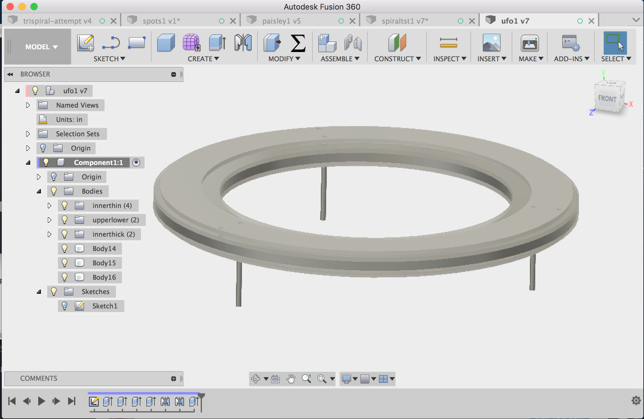
04/08/2017 at 19:11 • 0 commentsThis week's lamp is an experiment with circles and laser-cut acrylic & plywood. It emits light radially from both its inner and outer edges. Thus it is also a first attempt with what I'm calling "negative space" lights, where the lamp defines and illuminates an internal region that doesn't contain emitters. In this simplest case, it's the center of the ring.
![]()
This lamp's construction is essentially a "sandwich" of an acrylic inner ring encapsulated by two plywood outer rings. The whole assembly is held together in compression by long machine screws and aluminum standoffs. It can be placed on a table or hung against a wall. The LEDs side-emit through the acrylic to create a halo of light that bounces off the surface the lamp is on. The white faces of the inner ring emits a soft glow. The feet can be swapped to be low or tall, depending on the light bounce effect desired.
As with all these lamps, this one is dynamically controllable. Primarily you can control the "arc" of light that is emitted by changing which LEDs are turned on, as in this video. (And like all these prototypes, this is not the intended UI, just a simple set of potentiometers)
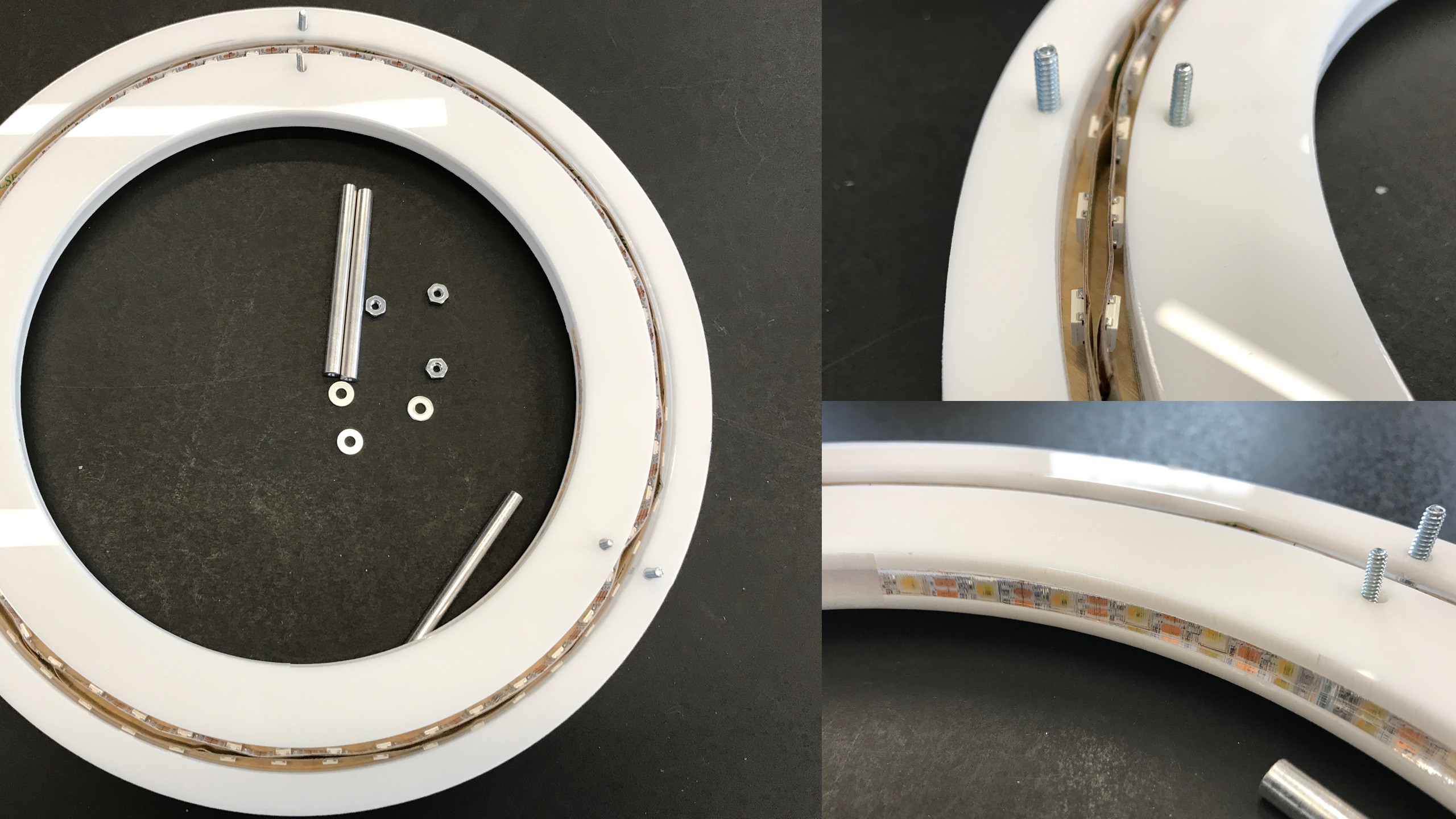
The LED strips are mounted both facing inwards and facing outwards, placed in a channel created in the inner acrylic layer. The innermost acrylic is clear and you can see the LEDs from the outside when they're in their channel.
![]()
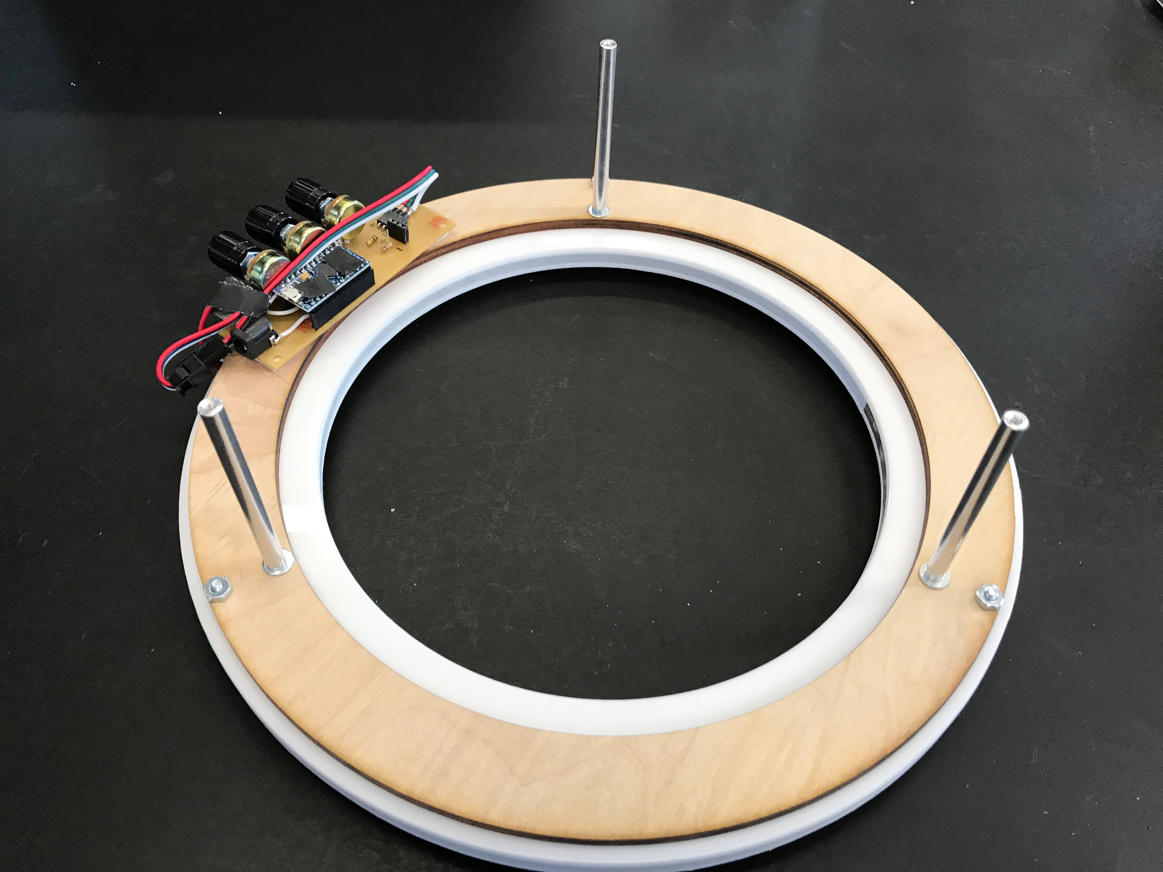
The inner and outer rings of acrylic (which would normally be free-floating) are registered and held in placed by 3 pairs of screws that also go through the outer wood layers. These wood layers cover the LED channel, lock the acrylic rings in place, and keep the LEDs secured without needing adhesive.
![]()
(In the above image, you can see the temporary UI & LED driver board from before that's rather unceremoniously foam-taped to the bottom)
Edge-lighting Acrylic and Diffusion
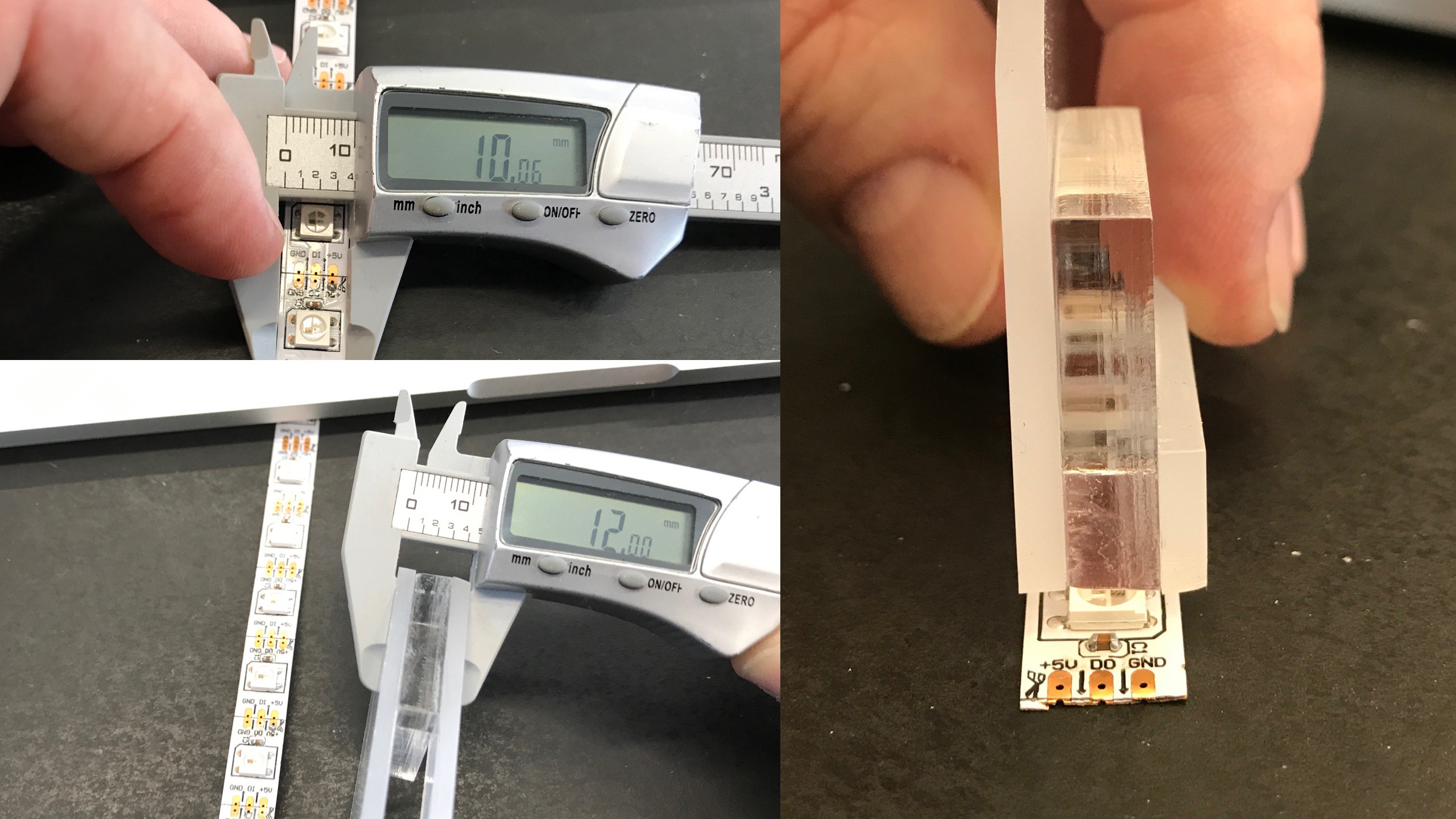
If you've ever tried to edge-light acrylic sheet with LED strip, you may have noticed a problem. LED strips are typically around 10mm wide but standard 1/4" acrylic sheet is only 6mm wide. This is enough to cover the 5mm LED but not enough for the entire strip. If you want the acrylic to completely cover the strip, you need to use two 1/4" sheets. But then the seam is directly over the LED, and that looks crappy. What I like to do is take two 1/8" sheets and use them to sandwich a 1/4" sheet.
![]()
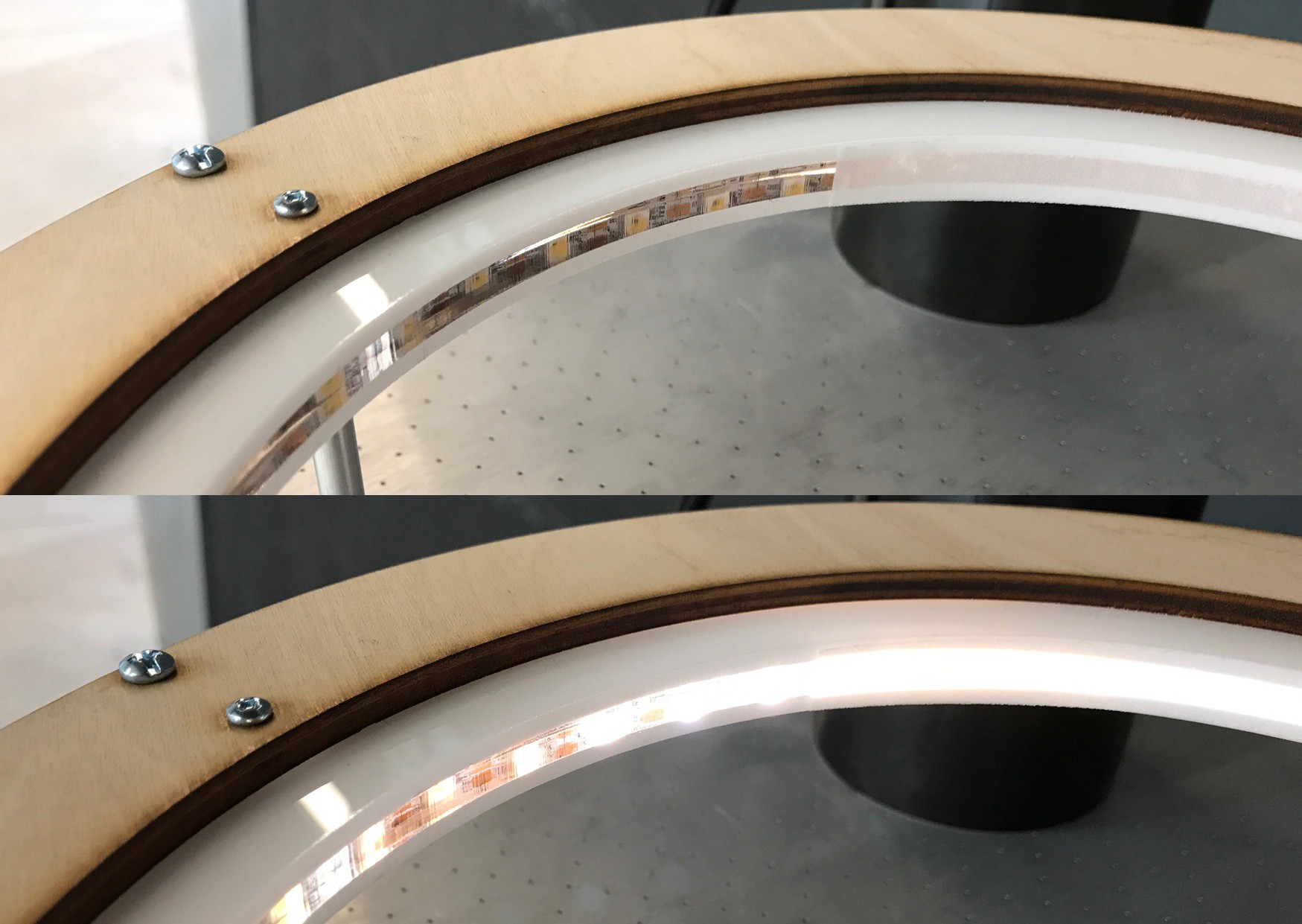
This creates a 12mm wide structure that completely covers the strip and creates a nice edge-light effect. By using different types of acrylic for the 1/4" vs 1/8" sheets (as I did here), you can create different effects. In this case, I wanted the light to come directly out but have the upper and lower ring faces glow. To accomplish this, I used clear acrylic for the 1/4" center edge-lit sheet and 1/8" frosted white acrylic for the top and bottom pieces. The result was pretty nice, but the edge-lit acrylic edge faces needed some diffusion. To solve this, I finally got to use the roll of frosted privacy screen film I got off Amazon. It works great!
![]()
This film is meant to adhere to clean class via static cling. Between the thinness of the 12mm (1/2") strips I made for the ufo edges and the fact that edges of laser cut acrylic aren't perfectly smooth, static cling wasn't going to keep the strips on. It turns out, coating the diffuser film strips with a light coating of spray adhesive made them stick great. The stuff is clear so no optical issues and it's repositionable for a time after spraying, making it easy to apply the strips around the curve of the ufo.
The end result turned out pretty good and matched up well with my initial CAD sketch.
![]()
![]()
-
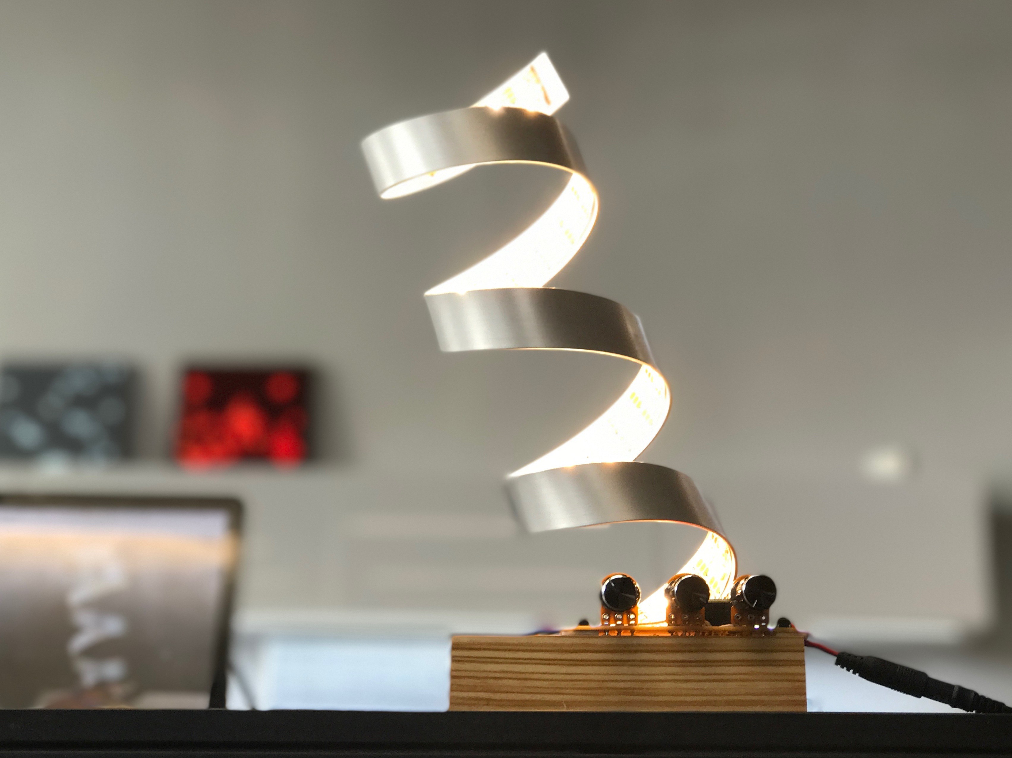
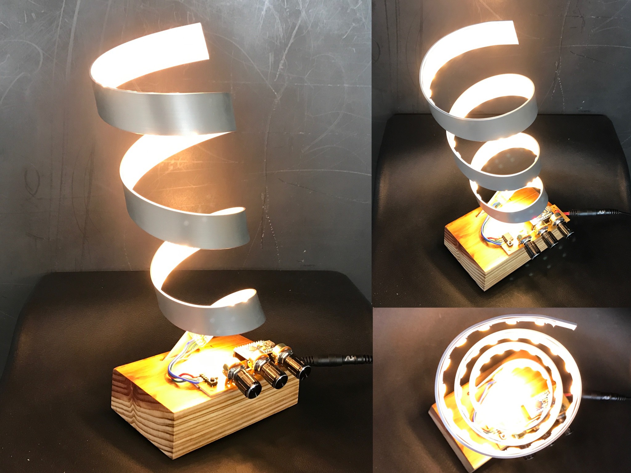
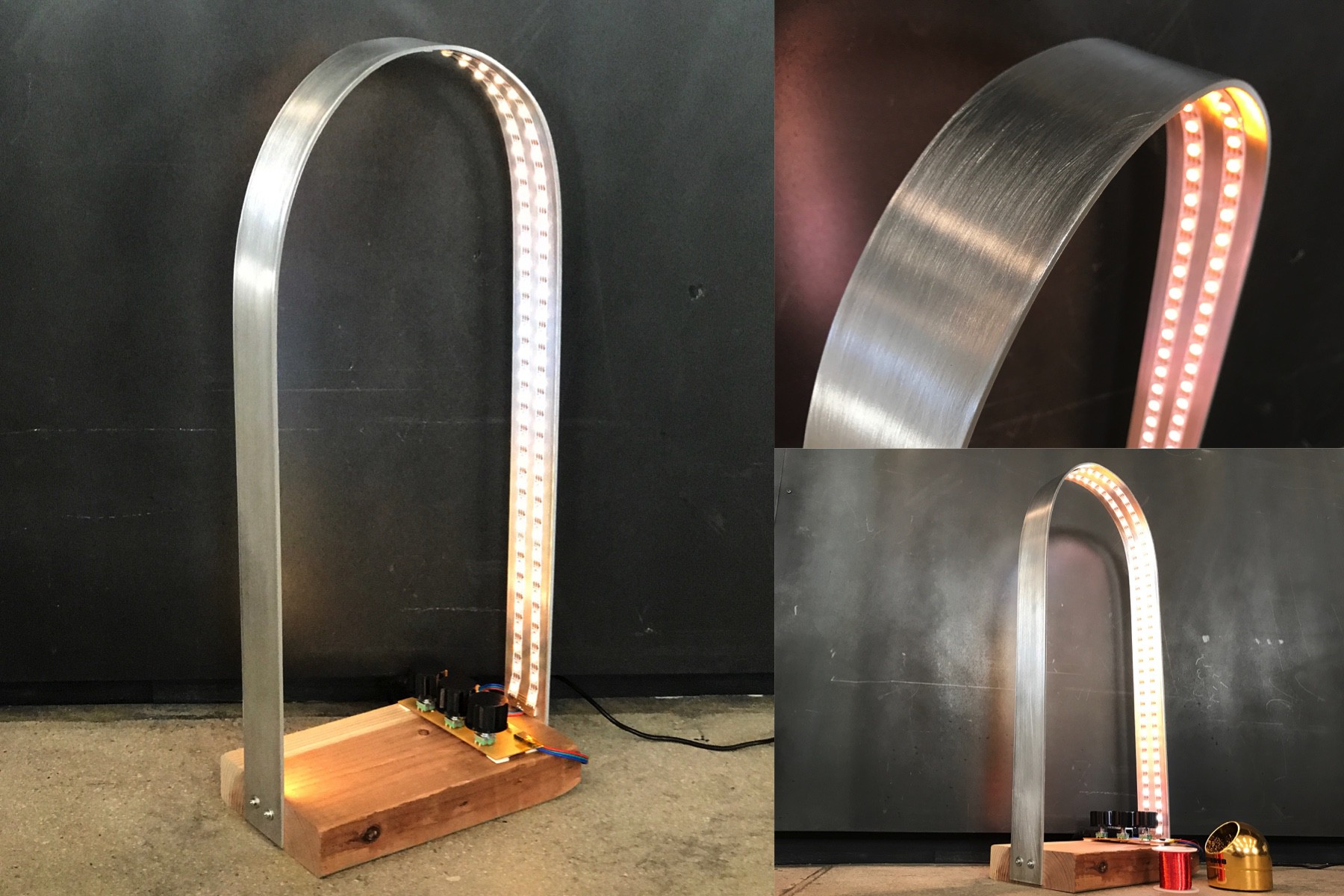
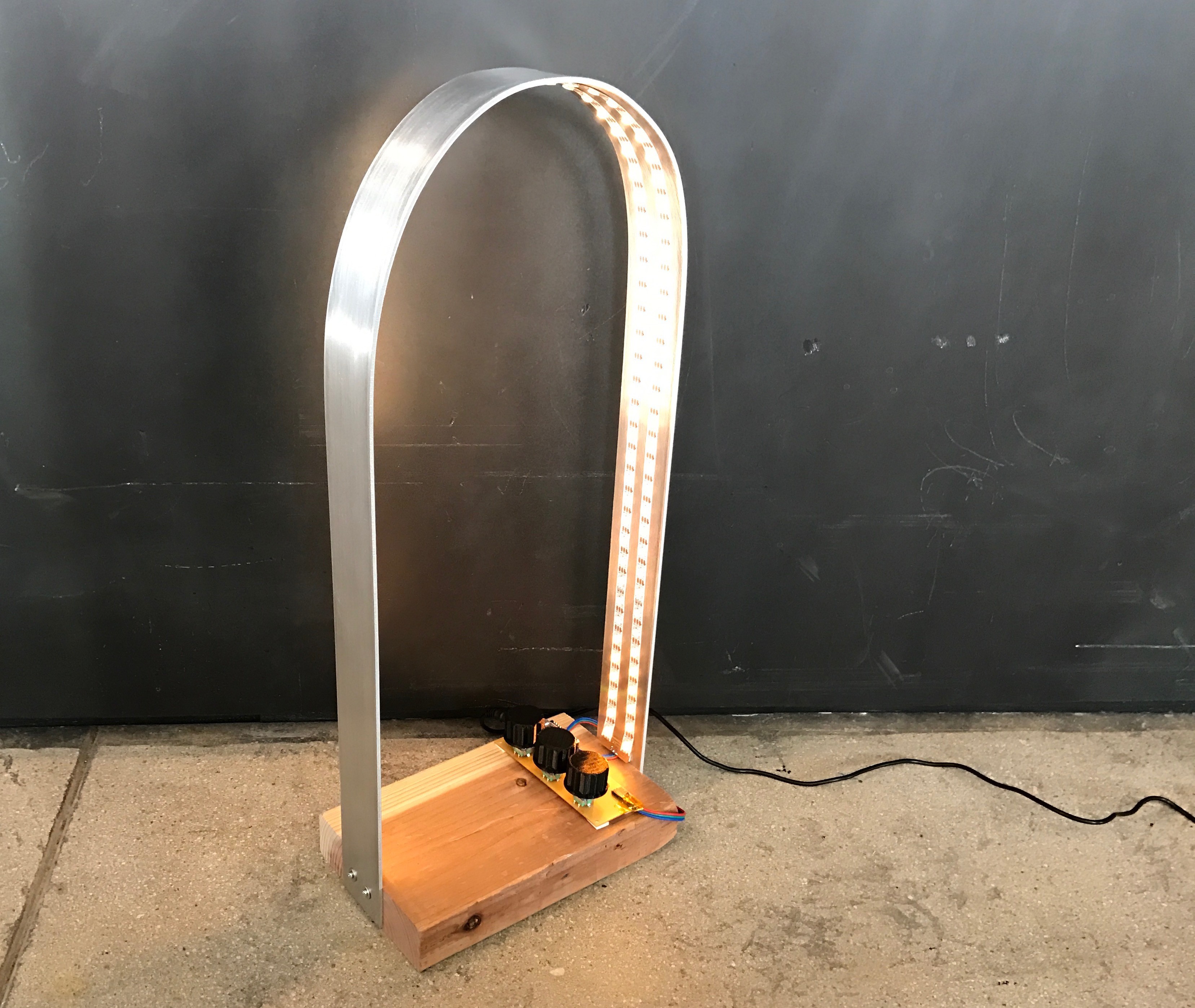
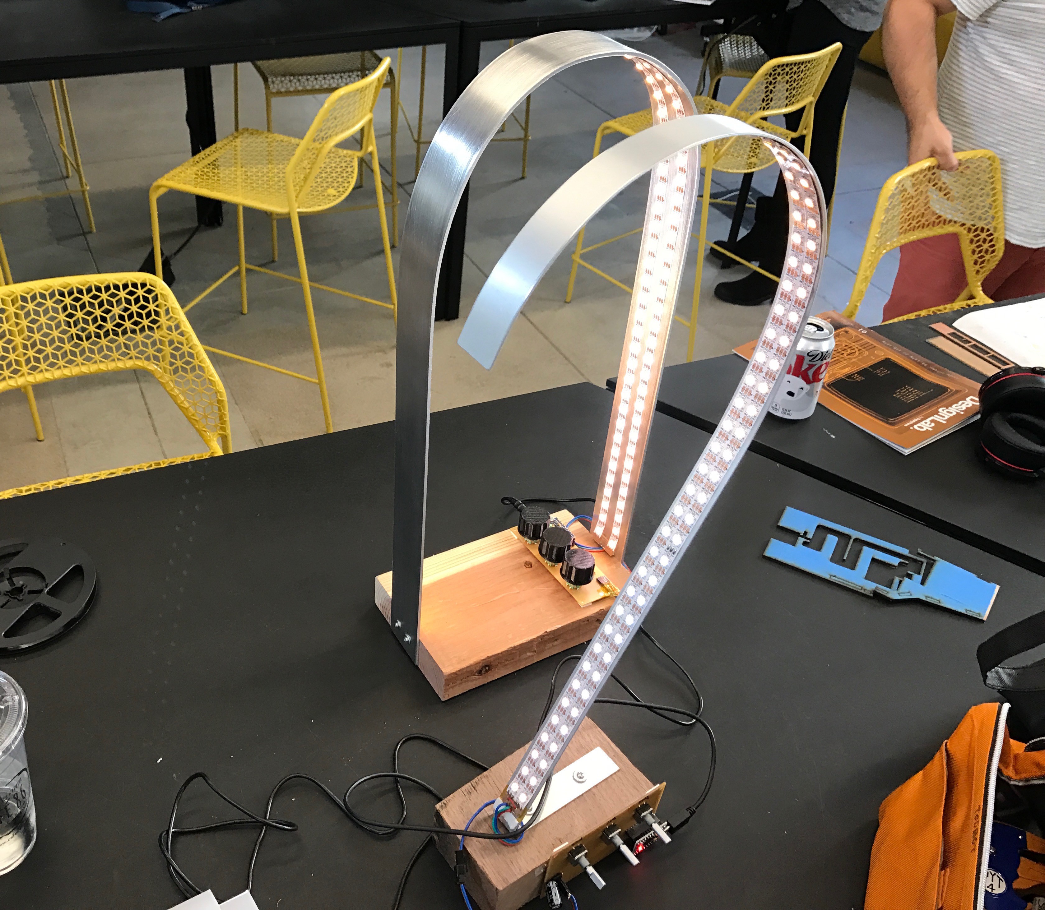
Lamp prototype #3: helixMetal1
03/31/2017 at 23:16 • 1 commentThis week's lamp is called "helixMetal1" and is a first experiment with spirals and helixes. This lamp continues the material exploration of bent aluminum bar, wood base, flexible WWA WS2812 LED strip and my simple LED driver board.
![]()
![]()
Here's a small video showing it in action:
As you can see, this lamp is comparatively small. It's probably one of the smallest I'm going to create. It could handily work as a desk lamp, but I generally am thinking larger and want to build a few floor lamps after this. Structurally, this lamp is exploring the tightest radius possible with these standard LED strips. I think 75mm diameter radius is about as small as you should go.
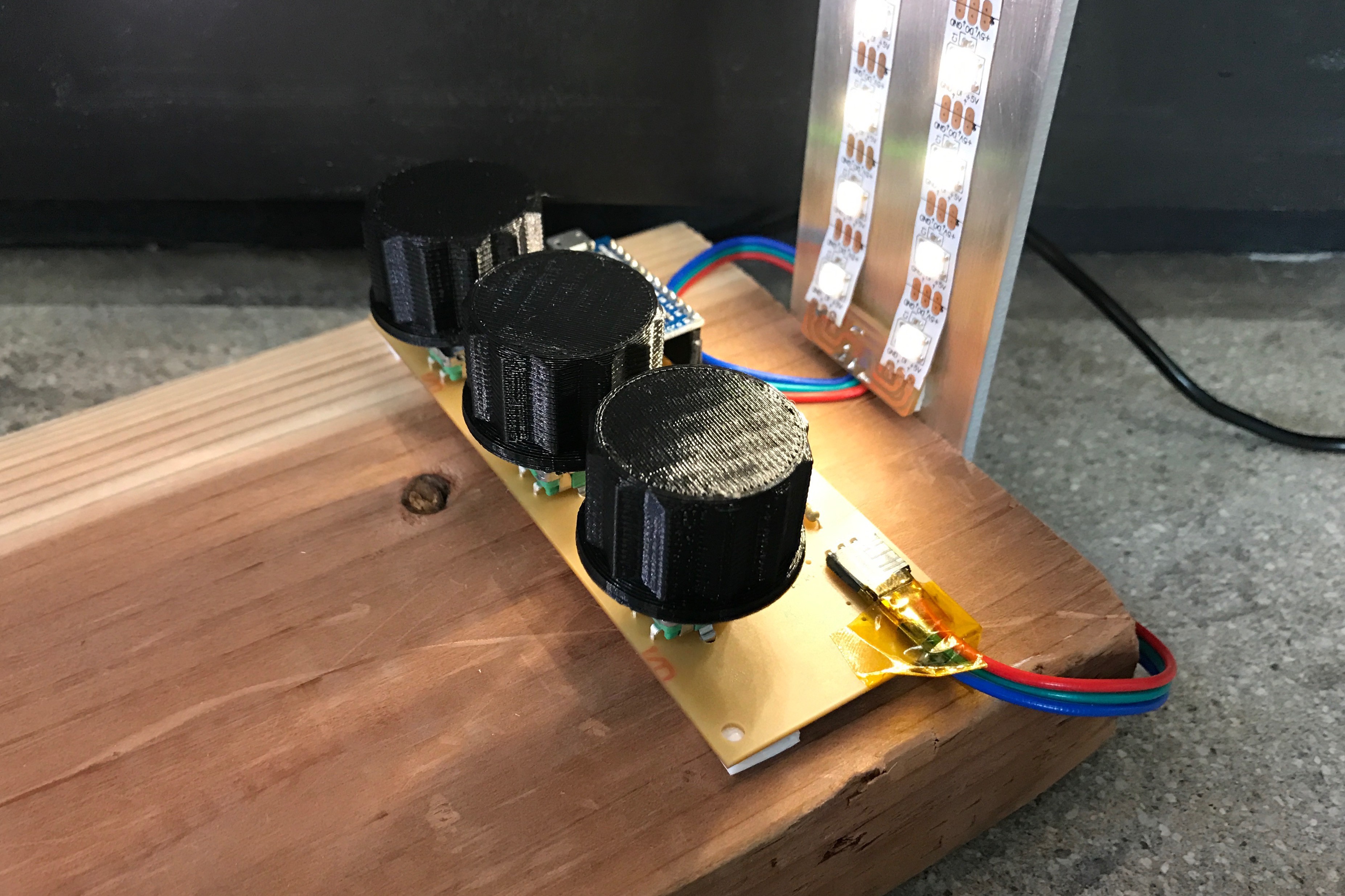
This prototype has three potentiometer knobs to play with the capabilities of the lamp. Those knobs control:
- Overall brightness
- Amount of LEDs lit (starting from top going smoothly to bottom)
- Color temperature from amber through warm white to cool white
Like previous prototypes, the electronics are purposefully exposed. I initially was a bit embarrassed by this but now I'm kind of liking the aesthetic. My original intention was to hide the electronics but maybe they get enclosed in something clear? (Maybe potted in clear resin even?)
This lamp also does not show any diffusion experiments. Next week is documentation for that. I have some potentially promising results and an interesting new idea. Stay tuned for that.
Some of the challenges I have been facing while working on these lamps:
- I still haven't had time to get on the Shopbot to try some of wood-based ideas. Not a huge issue, but I'd like to get a feel for how that material works as a 3d material (instead of sawing flat stock like you do without a CNC mill)
- Bending aluminum bar accurately requires more than jig when exploring. Some sort of mechanism. I think this bender on Amazon would work and I think I'll order it now. It's difficult to find a non-pipe bender that'll work for flat stock.
- I also haven't found a good way to collapse the UI to allow ease-of-use but still expose the dynamism and playfulness these lamps are capable of. A bank of knobs is fun for nerds but for general use it won't do. But maybe like the exposed electronics it's to be embraced?
- Photographing LEDs is an ever-present challenge.
-
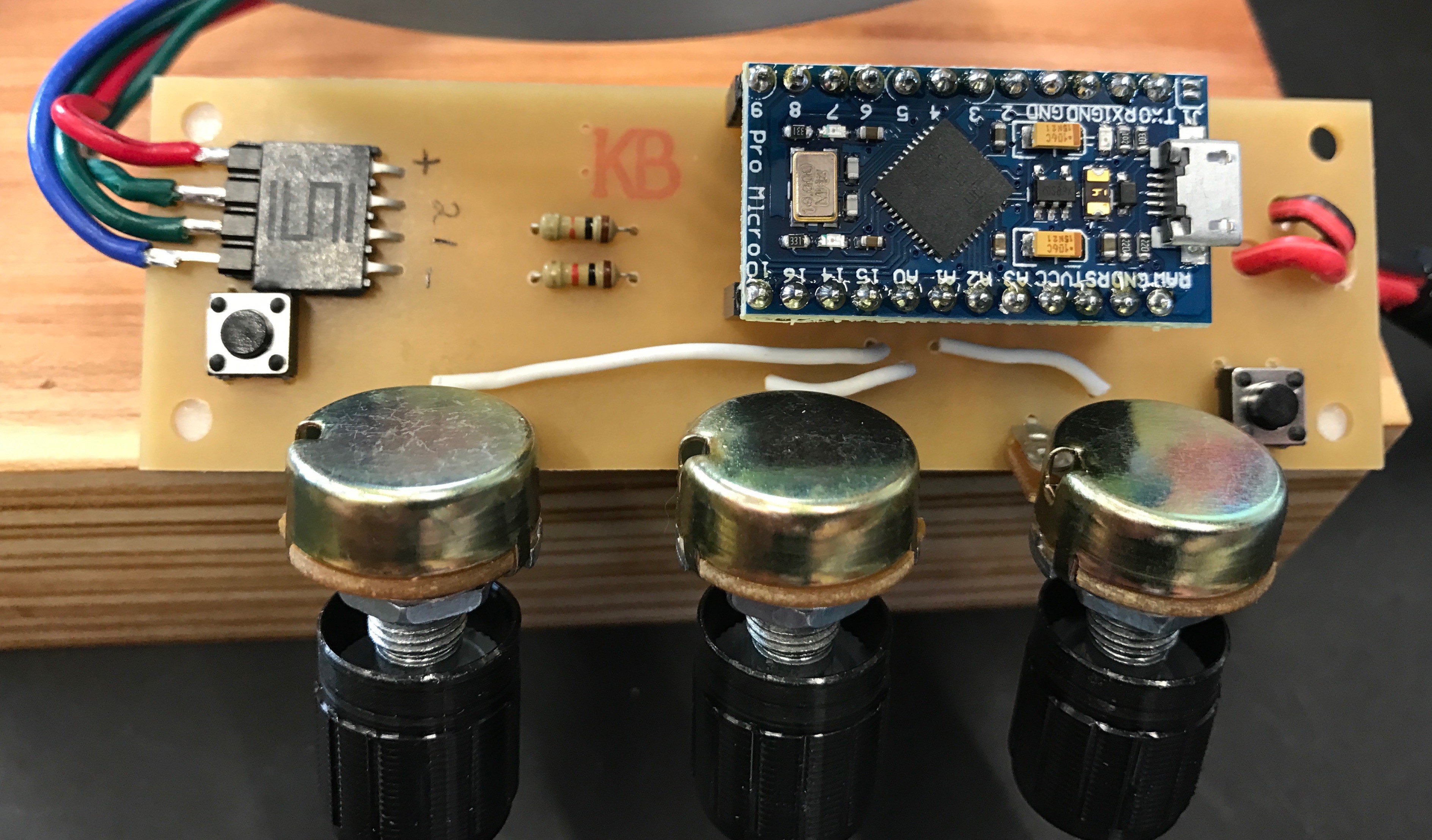
New lamp driver board: all pots
03/31/2017 at 22:09 • 0 commentsThe lamp drivers I have been making for ILOVELAMP are very simple carriers for the following:
- Arduino Pro Micro
- Power jack
- LED output jack
- Various sensor inputs (knobs,etc)
I chose a Pro Micro because I wanted a 5V microcontroller that had: a decent amount of I/O, analog inputs, pin change interrupts on most pins, I2C/SPI, easy to program / built-in USB, and good support with FastLED. The ATmega32U4-based "Pro Micro" is fits most all these and you can get a 5-pack from Amazon for $27. I don't need or want BLE or WiFi yet (or potentially ever) and didn't want to deal with the hassle of 3v3 to 5V conversion for WS2812s.
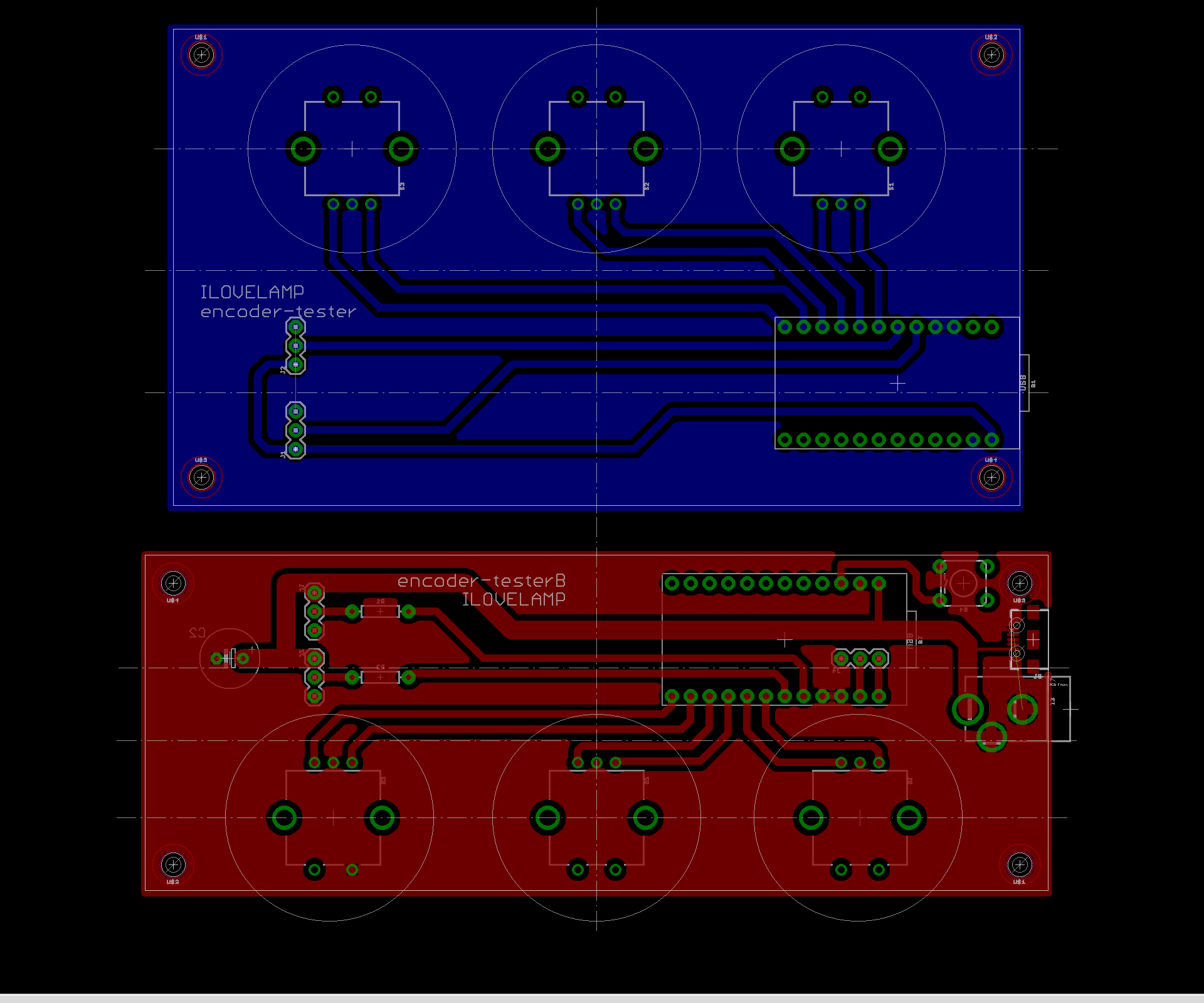
The first two of these lamp driver boards I made explicitly had mounting for standard rotary encoder knob inputs. I love rotary encoders and thought they could be a good input method for the lamps. After using them for a few weeks, I think there are much better alternatives.
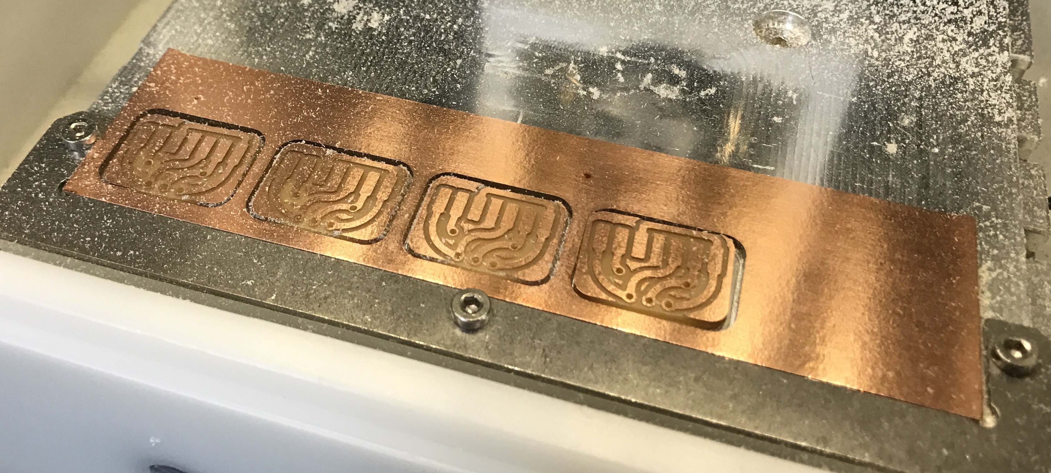
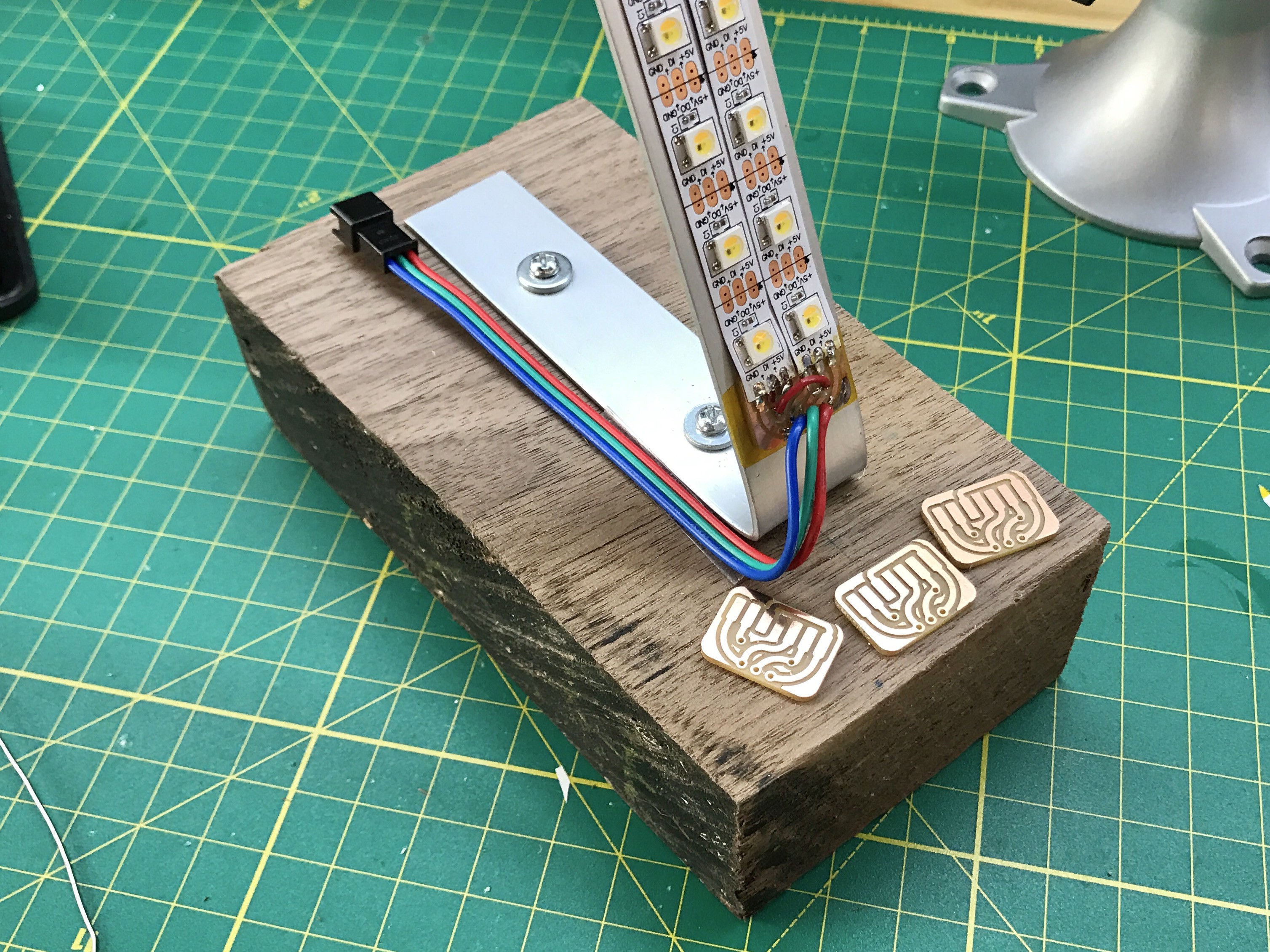
One obvious alternative is potentiometers. So the current board I designed and am using is a smaller version with pots instead encoders and has the ability to drive two LED strips more easily.
Here is the layout of the previous board and the new board.
![]()
I'm still keeping the traces exceedingly thick to make Othermill milling and soldering faster and less error-prone.
Here's the new board milled and populated.
![]()
A trick with the Othermill: try to always do a single-sided board. If you can't get single-sided to work, perhaps you can get away with a handful of "traces" on the other side that you then wire as jumpers. That's what this new board has for the pot wipers. Notice the three white wires on the top of the PCB. These are the "bottom" traces (colored blue) in the board layout above.
Another Othermill trick: put your traces on your "top copper" layer and your through-hole components on the "bottom" of your PCB. Yes, you can mill the bottom of boards, but it's easier to think of the main copper layer as the top, even though with through-hole components it'll be on the other side.
-
DIY Linear Encoders for Slider Knobs
03/29/2017 at 22:25 • 2 commentsAlong with experimenting with lamp shapes, materials, diffusers, and LED types, I really want to explore different input methods for controlling these lamps. They have the opportunity to be so expressive, a simple on/off switch or dimmer seems too restrictive.
That's why my initial test board to drive the LED strips also had three rotary encoder knobs on it. I feel rotary encoders are more interesting, since they offer "infinite" rotation and effectively report the delta of the angle rotated. Unfortunately commercial rotary encoders have fairly low PPR (pulses per revolution).
So let's build our own encoders! But instead of rotary, what if they were linear? Can we make our own sliders? And if so, can they be made on a curve? Turns out, the answer to all these is yes.
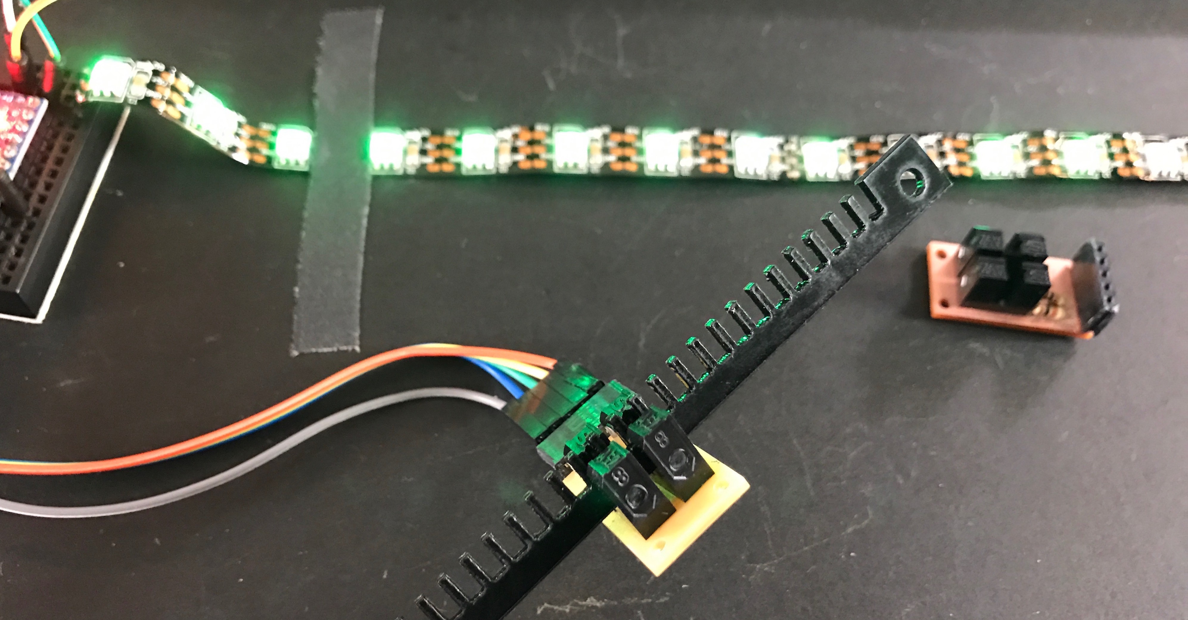
![]()
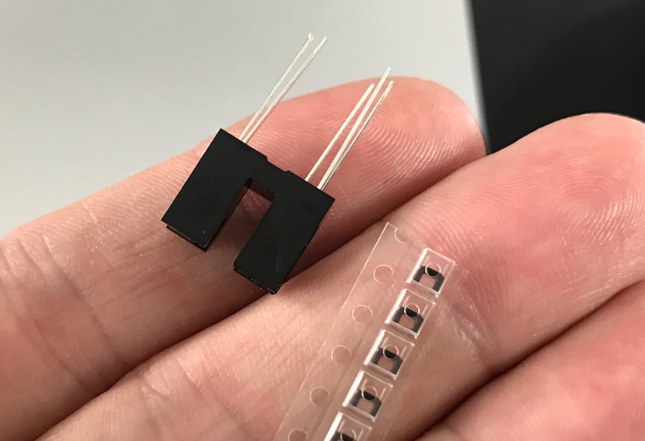
In use, I'm imagining the encoder strip is mounted stationary and the slider knob is the PCB with the optointerrupters. I think that can be made robust. The cable to the interrupters can be made light. (only four wires are needed) And it would allow the encoder strip to be curved to follow the shape of a lamp. The interrupters used in the test are some of the most common (and thus the cheapest) but they are quite large for this use. The "slider knob" PCB could be made *much* smaller. For instance, here is a comparison of the interrupters used in the test and the super tiny interrupters used in some digital cameras:
![]()
So tiny!
The test circuit was created by mounting two standard optointerrupters on a PCB and making an interrupter strip on the laser cutter. This created a quadrature signal just like a regular rotary encoder. So, the standard Encoder Arduino library could be used to parse the output of the interrupters. The code used in the above example is on the ILOVELAMP github as "diy-linear-encoder-test0.ino" so you can see how simple it is.
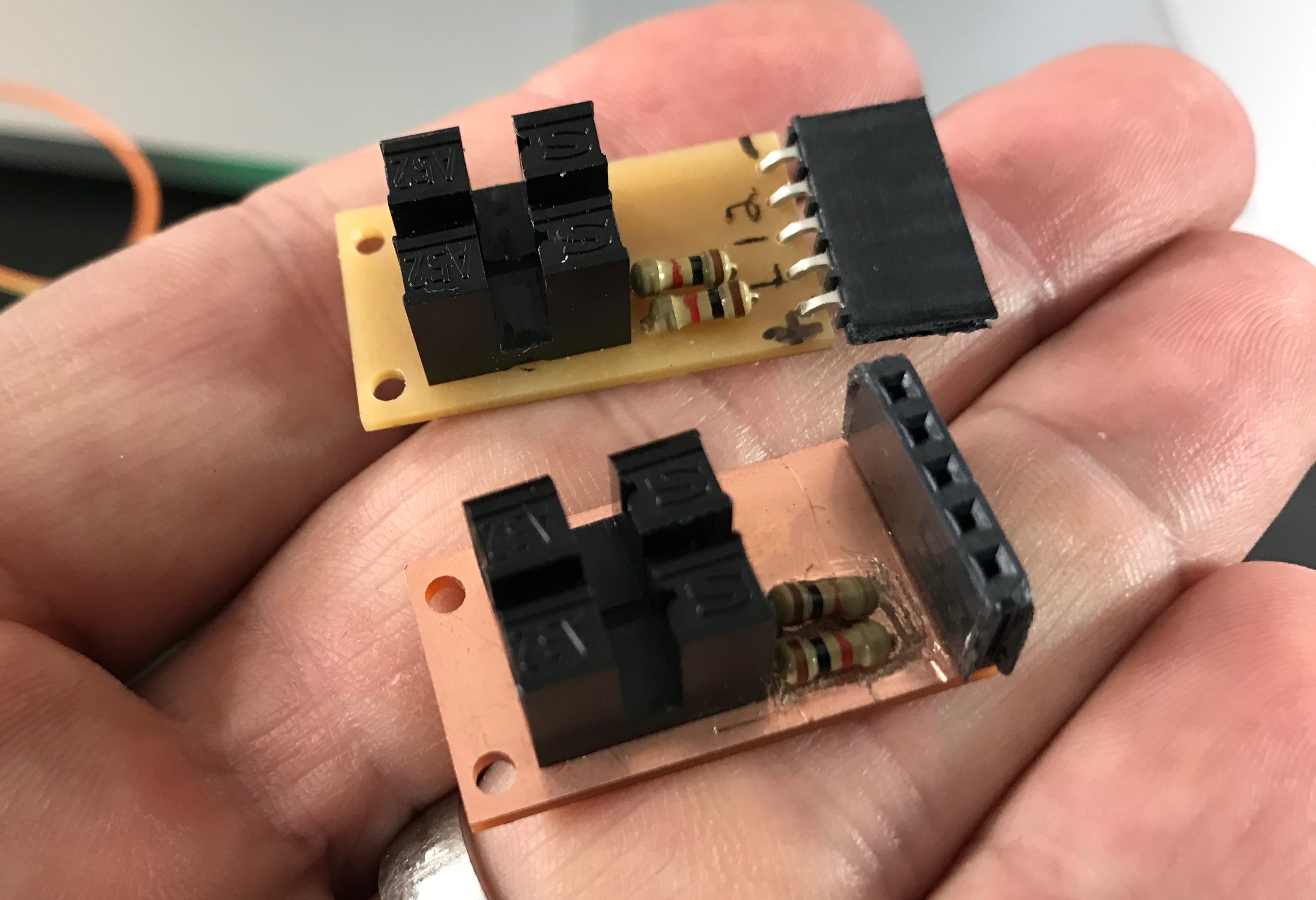
The schematic & PCB for this test is equally simple:
![]()
One thing I neglected to remember when I first made this PCB on the Othermill, is to use a single-sided board blank when milling a single-side board! If you have *any* through-hole components, they will short together on the unused (but covered in METAL) side of the PCB.
![]()
Ooops. I ended up frying two optointerrupters but it was a good reminder about always checking what kind of PCB blank I'm using.
-
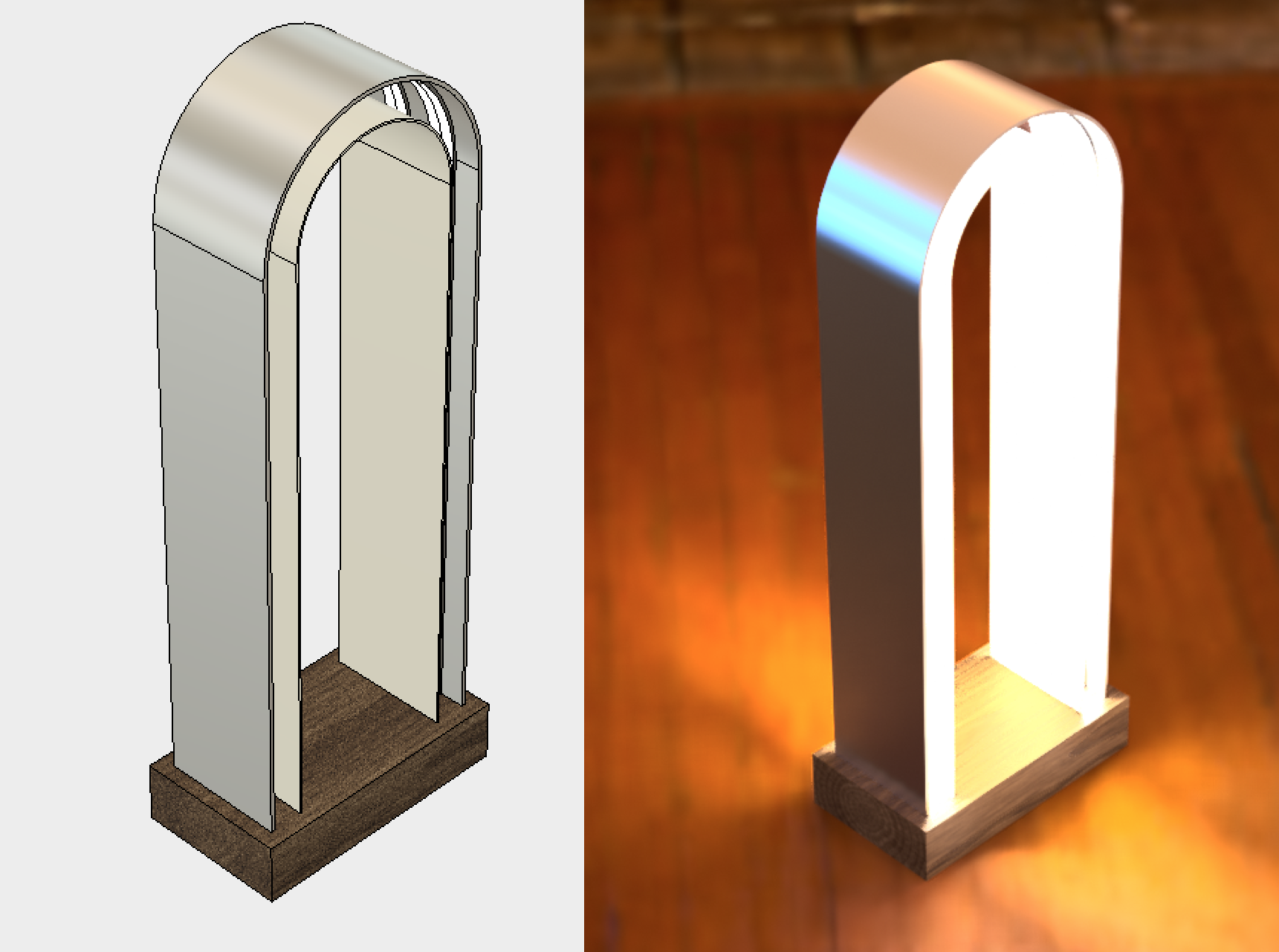
Lamp prototype #2: "archMetal1"
03/18/2017 at 01:27 • 0 commentsThis last week has been spent getting more up to speed tools like the ShopBot and designing lamps that can be accomplished using tools available in the Design Lab. This next design prototype is called "archMetal1".
![]()
This design is a better platform than the first lamp for testing flexible but structured diffusion materials (plastic PP & PET sheets, maybe velum, but not cloth or plexiglass). The design consists of a main metal arch embedded in wood, with the LEDs attached on the inner side of the arch. The diffusion material attaches with standoffs from either the centerline or edges of the metal bar, like this:
![]()
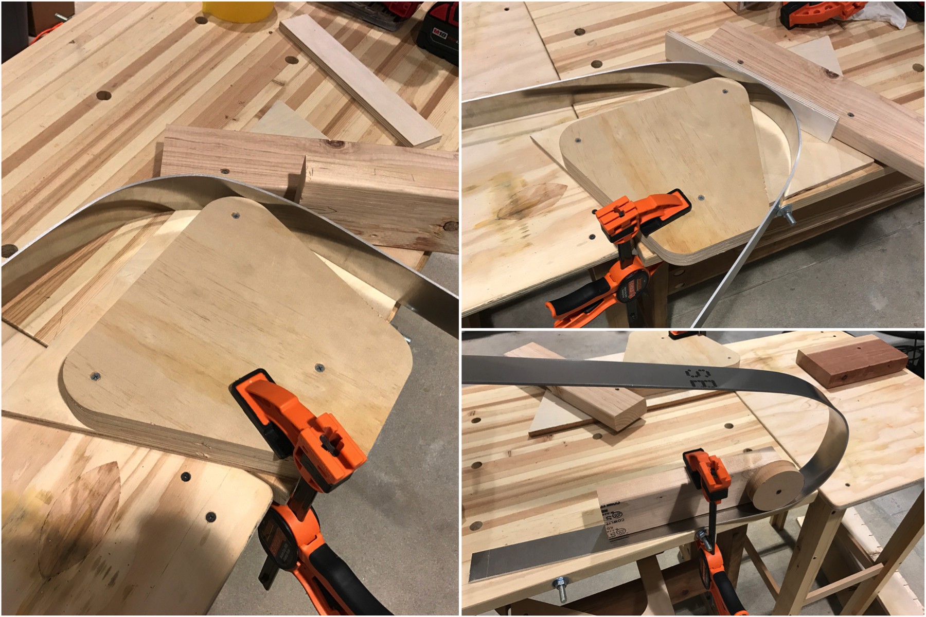
Can we prototype this up in a few days? The design specifies a 4"-wide bar of aluminum at 1/8" thick and 48" long, sunk into a 9"x5"x2" wood block. All I had was 2" x 1/8" x 48" aluminum bar. This should still be wide enough to demonstrate the design and for future diffusion experiments.
That width turned out for the best given that the Design Lab doesn't yet have the metalworking tools needed and I don't have full command of the ShopBot yet to make my own tools. I think this bender might work for me in the future. For this prototype, I faked up a few metal benders using scrap wood, based on what I've seen on Youtube, particularly this video:
![]()
These benders worked up to 120º bends but I did end up manhandling it quite a bit to get it into the shape I wanted. And even then it's not very even due to the lack of precise tooling. Oh well, this is a prototype after all. After a small amount of sanding, the U-shaped bar was mounted to a block of solid wood.
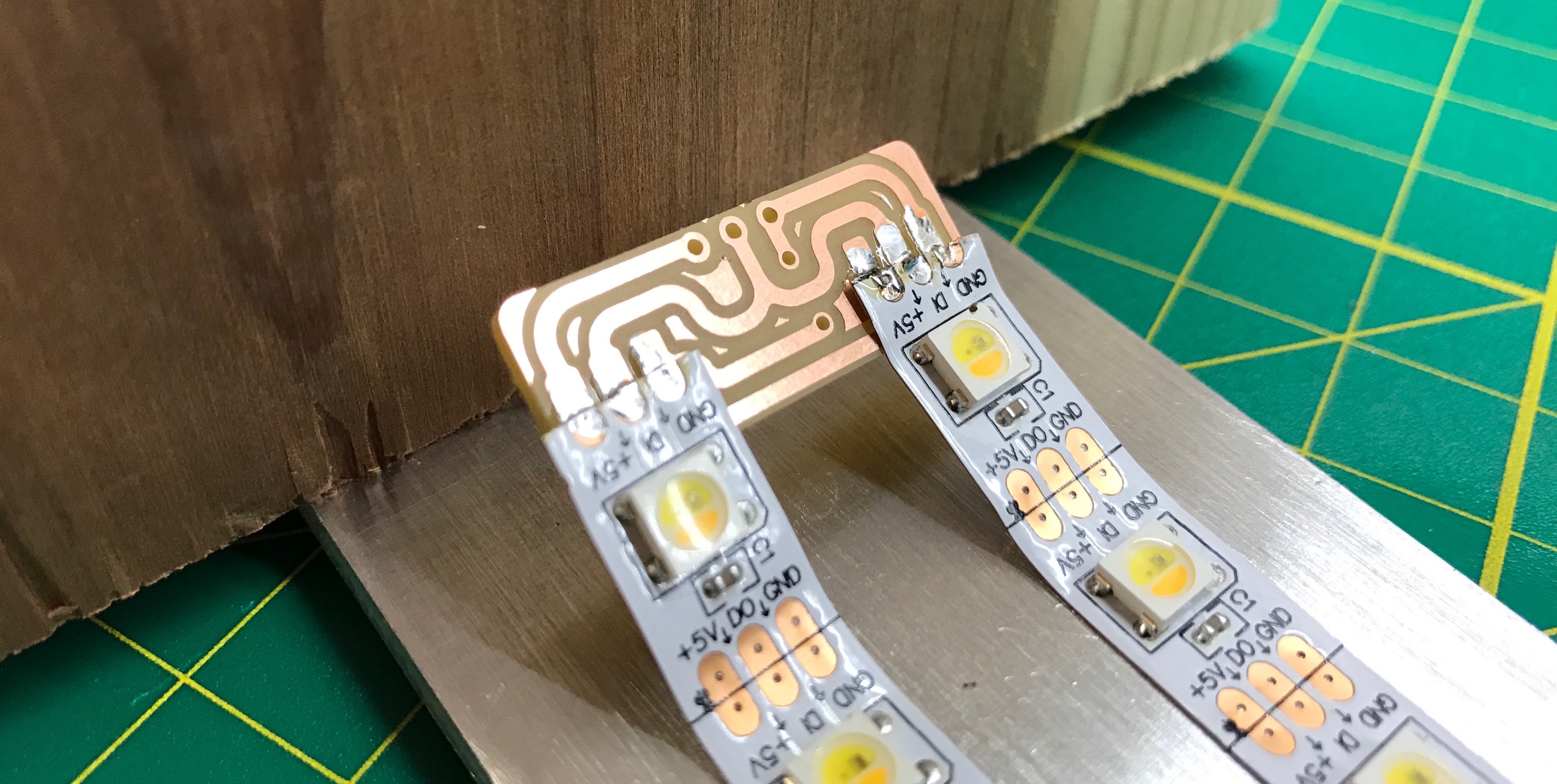
The next step was laying out the LEDs and wiring them up. The original design calls for four LED strips arranged as two pairs, with space in between and on the sides. With the smaller 2" bar I reduced the number of strips to two so I could have the spacing I wanted for diffusion standoffs. To help with wiring, I quickly made a special NeoJoint splitter in Eagle to accommodate the spacing. After a 2-minute milling on the Othermill I had it and It works great. And it looks pretty neat:
![]()
I also made an updated version of the rotary encoder test board. It's lower profile and features a separate DC power input for easier stand-alone operation. It also swaps top & bottom copper layer because on the Othermill, it's faster to mill top copper (saves a button press). In the image below, original test board is on top, the updated one is below it.
![]()
I milled up one of these on the Othermill, populated it, tested and mounted it.
![]()
All that's left is to upload a test sketch to the Arduino Pro Micro that's driving the lamp and power it up. This is the result.
![]()
![]()
It turned out okay. With dynamic patterns on it, it really comes to life.
Here it is in size compared to lamp 1. About the same height but much more stable.
![]()
Next steps:
- Gain control over ShopBot to try out some wood-based ideas
- Mod this lamp to add diffusers
-
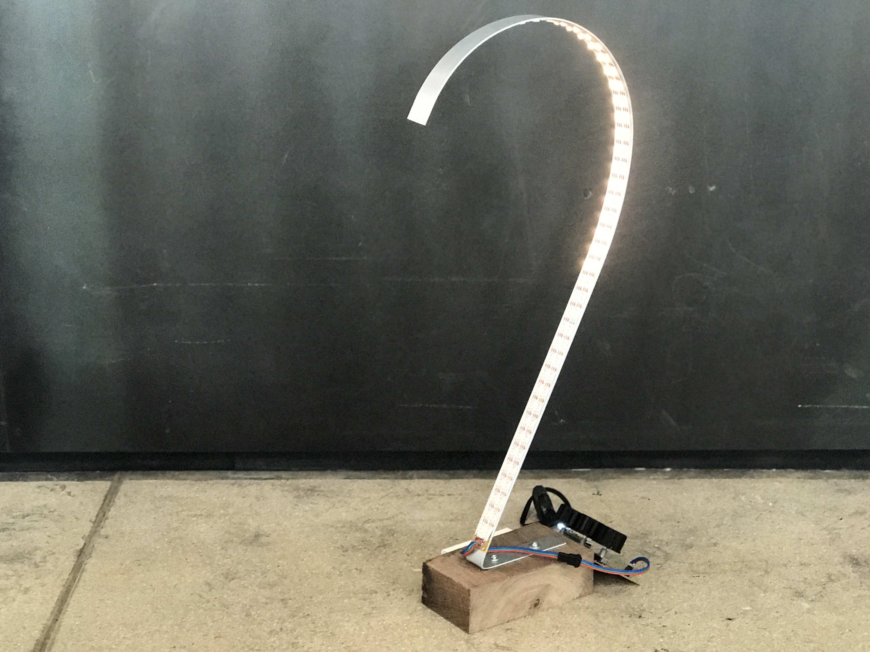
Week 1: first lamp idea done (mostly)
03/09/2017 at 23:36 • 1 commentAfter having this idea so many years ago, I finally have a desktop-sized extant version of it. It's pretty cool.
![]()
It's made from cheap aluminum extrusion, a chunk of waste walnut, WWA LEDs strip, and my rotary encoder test board. It has several issues but the form exists and I can use it as a platform to bounce future ideas off of. And now I can finally put this idea to bed after having it rattle around in my head for so long.
This prototype uses two strips in parallel, so I needed to wire a cable to two strips. If you've ever soldered up stuff before, then you know wiring to *three* things is frustrating. But since we had an Othermill in the house, I spent 10 minutes designing a custom NeoJoints splitter and cut several out. The resulting solder up was super easy.
![]()
![]()
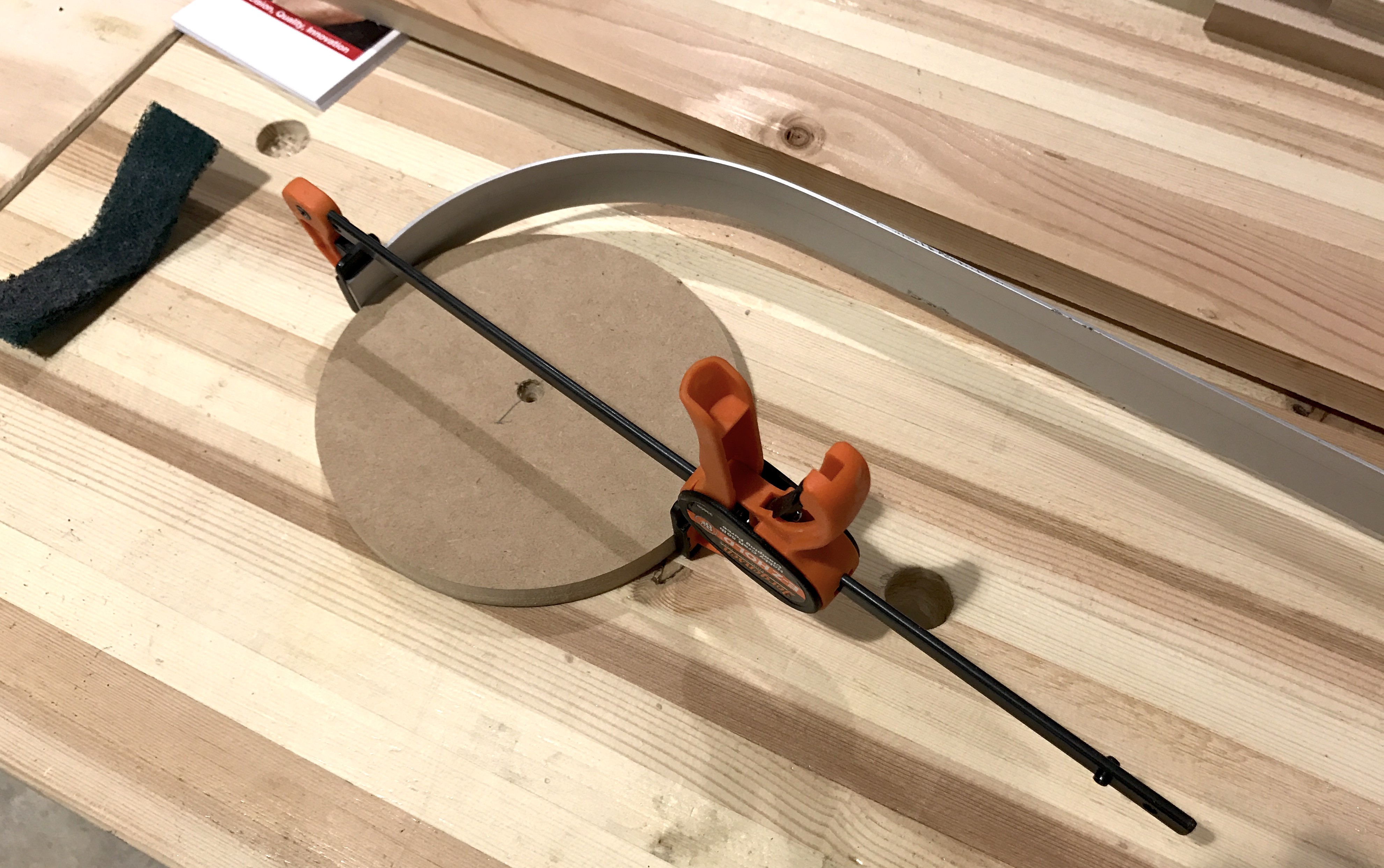
To form the arc, I used an existing MDF form that was laying around the Lab. While its radius was too small, it was actually good to use since the aluminum bar springs back after forming.
![]()
Next week: a different design and diffuser explorations
-
Knobs On
03/09/2017 at 03:25 • 0 commentsHere's a quick video of the rotary encoder test board with 3d printed knobs.
These knobs & encoders suck for the lamp UI, but at least it gives me three independent axes of control to experiment with.
-
Another input option: DIY rotary encoders
03/07/2017 at 06:48 • 4 commentsRotary encoders today mostly suck.
The "infinite turning" knobs you see on some products today are rotary encoders. The common commercially-available ones use mechanical wipers to sense rotation and have a low number of PPR (pulses per revolution, a measure of rotation) of 12-24. To me this is sad: it means your angular resolution is only around 15 degrees (360/24) and the friction from the mechanical wipers means you can't "spin the knob". These rotary encoders are ubiquitous though because they're so cheap: < $1.00 in single quantity.
![]()
One alternative to these is optical rotary encoders. They use LEDs & phototransistors instead of mechanical wipers to sense rotation. Unfortunately, they're almost 10x expense. These were the kind I used when I was a tiny EE and they were awesome.
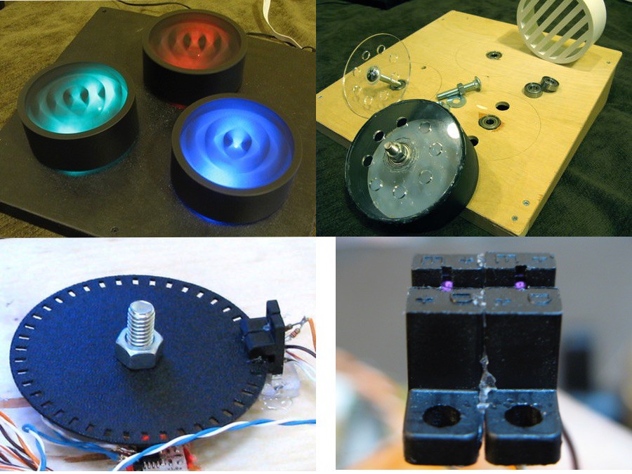
Several years ago (2008!), I built a set of three HUGE optical rotary encoders out of standard optical interrupter modules, rollerskate bearings, and PVC pipe caps. The resulting knobs were 4" in diameter and you could get them spinning for over a minute.
![]()
So I may experiment with making a few subtler, smaller versions of this idea
-
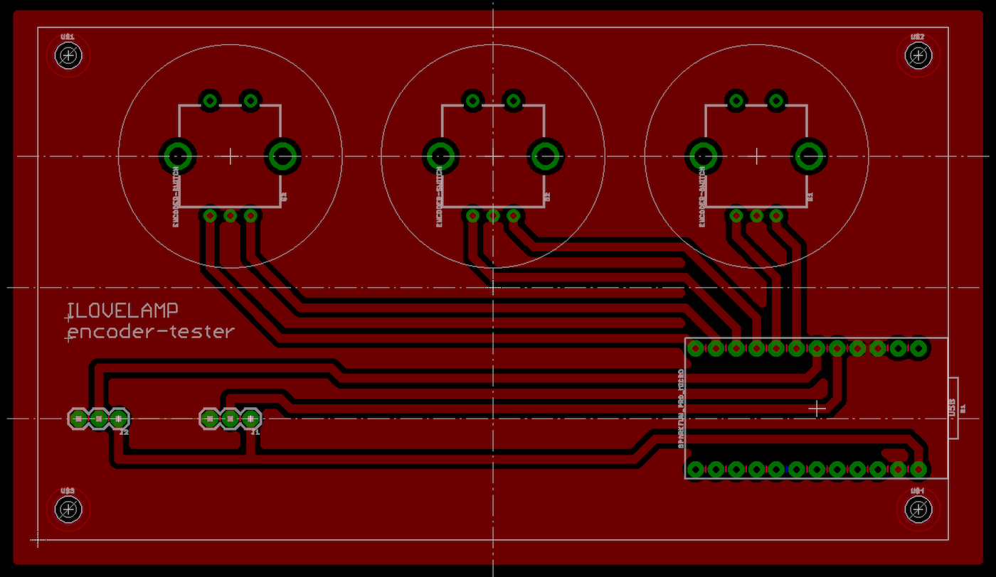
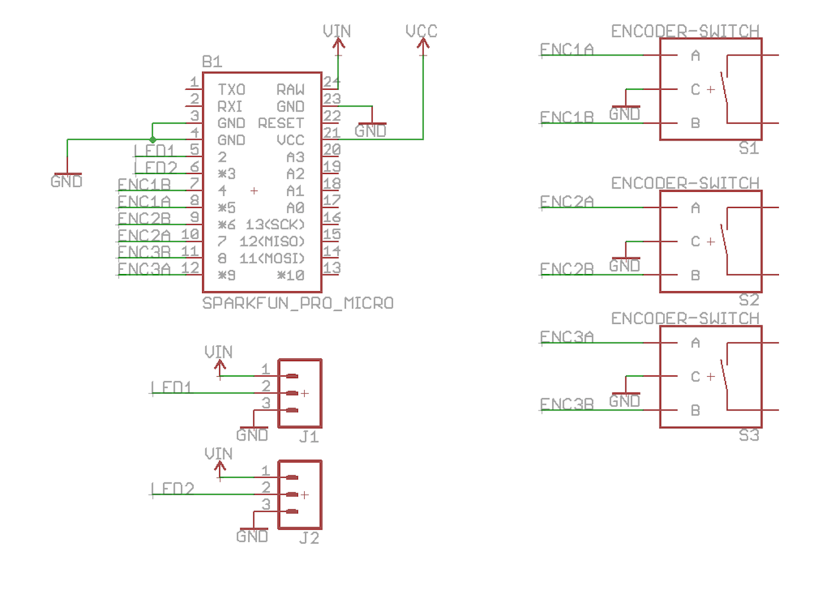
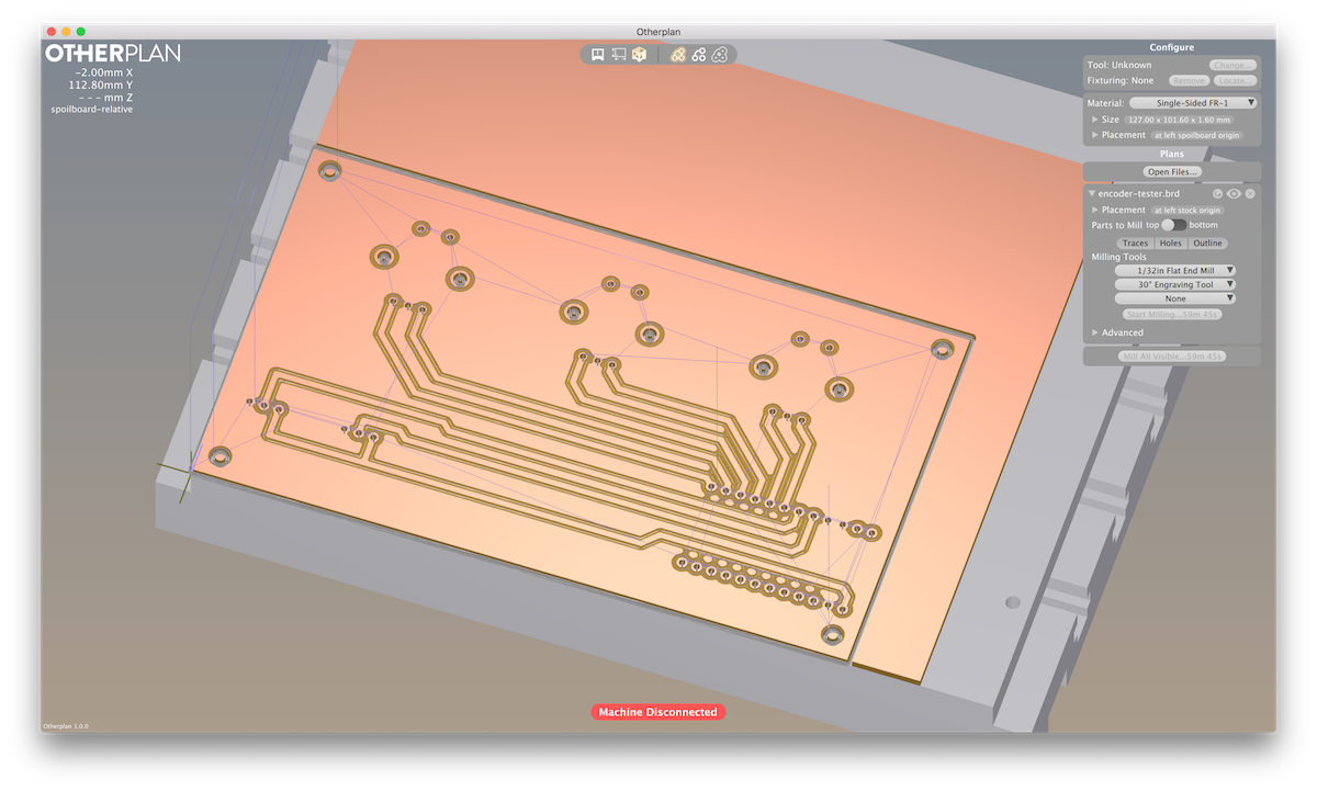
github & encoder tester
03/06/2017 at 23:34 • 0 commentsI worked up a quick and simple rotary encoder tester board. It may be that a good UI for the lamp is a couple of rotary encoders. Here's a quick board that is millable on the Othermill and mounts 3 standard PCB-mount rotary encoders, an Arduino Pro MIcro, and has two different LED strip outputs.
Time to start milling, then back to materials tests.
Also, I'm putting everything that is code & schematics in this repo: https://github.com/todbot/ILOVELAMP
I'm still not sure how to properly share Fusion360 models (The Autodesk A360 is much better than either Hackaday.io or Github, but it's really closed off), but I'll try to put models in the github repo too.
![]()
![]()
![]()
-
First day: Start!
03/02/2017 at 00:49 • 0 commentsToday is the first day of my SupplyFrame Design Lab residency.
In preparation, I've spent the last month getting up to speed on Fusion 360 and sketching out some (bad) ideas.
Here are some renders of those ideas. None of these are what I want. They are about playing with Fusion, thinking about designs I can make easily on a laser cutter or Shopbot, and experimenting with the "emissive" material type when rendering to get a baseline for how 3d renders match reality.
![]()
![]()
![]()
I LOVE LAMP
Explorations in creating lamps with flexible light emitters & curved surfaces