Utilizing a solder paste dispensing syringe, we apply solder paste to each component pad to begin the Main Circuit Assembly process. Here, we are utilizing Sn/Pb 63/37 solder paste, which has a melting temperature of 190 °C.
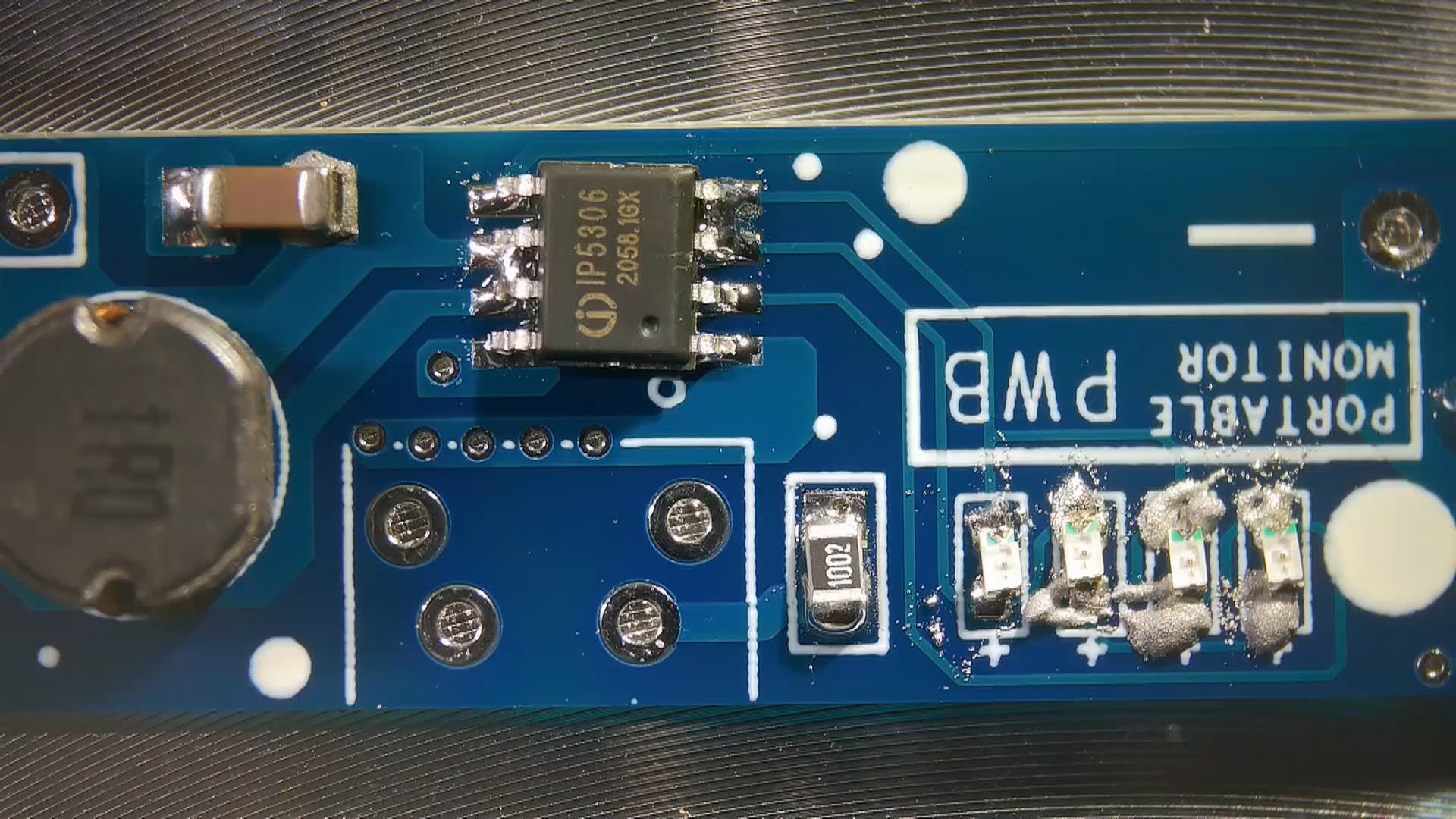
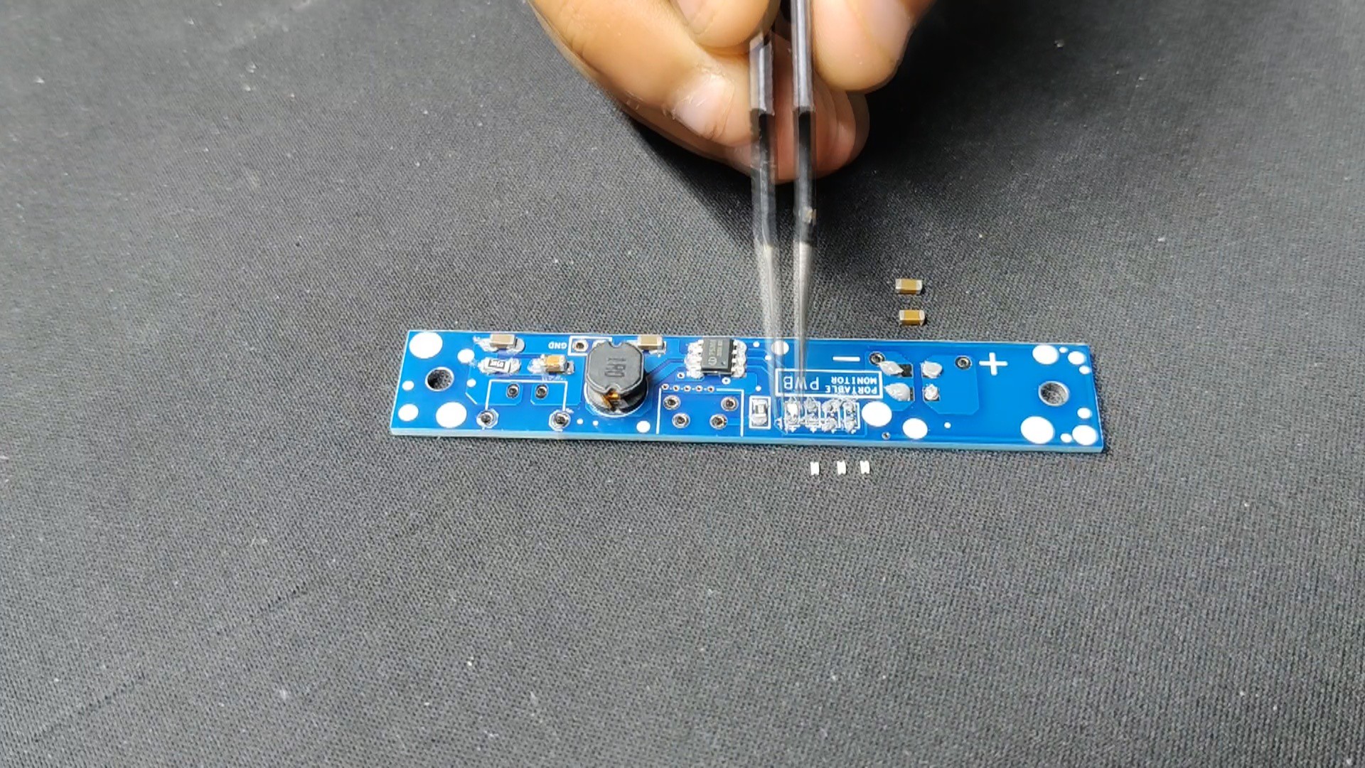
Next, we pick each SMD component and place them in their correct locations.
All of the components are then permanently bound to their pads when the entire circuit is set on the reflow hotplate, which heats the PCB to the solder paste melting temperature.
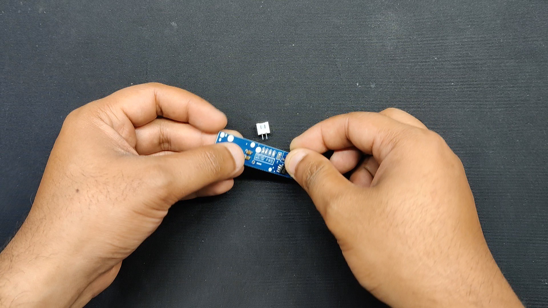
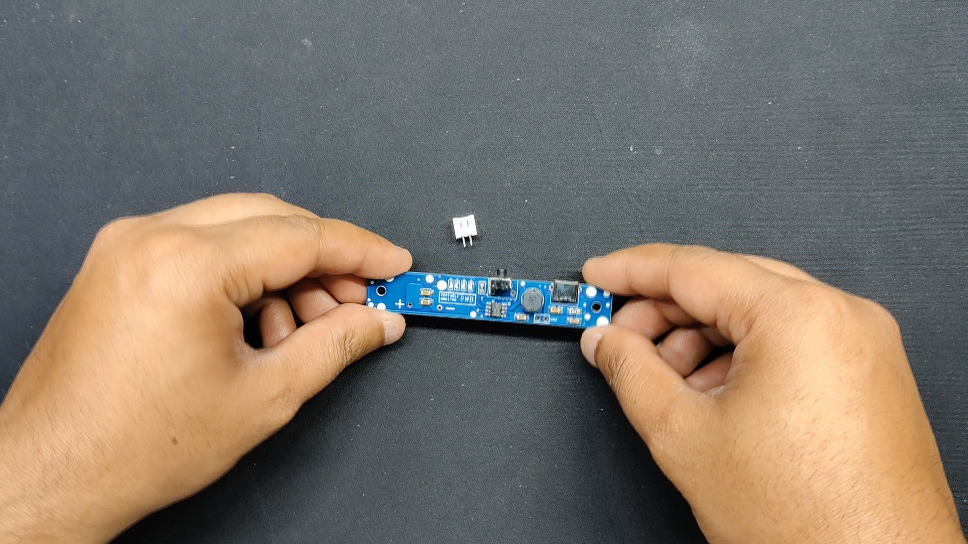
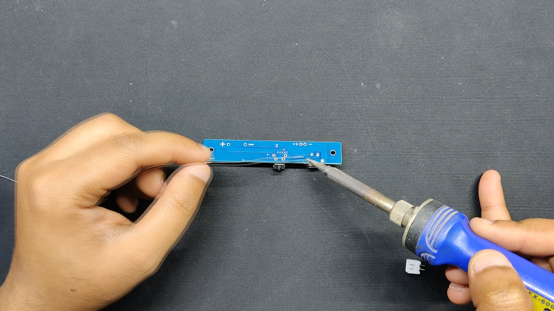
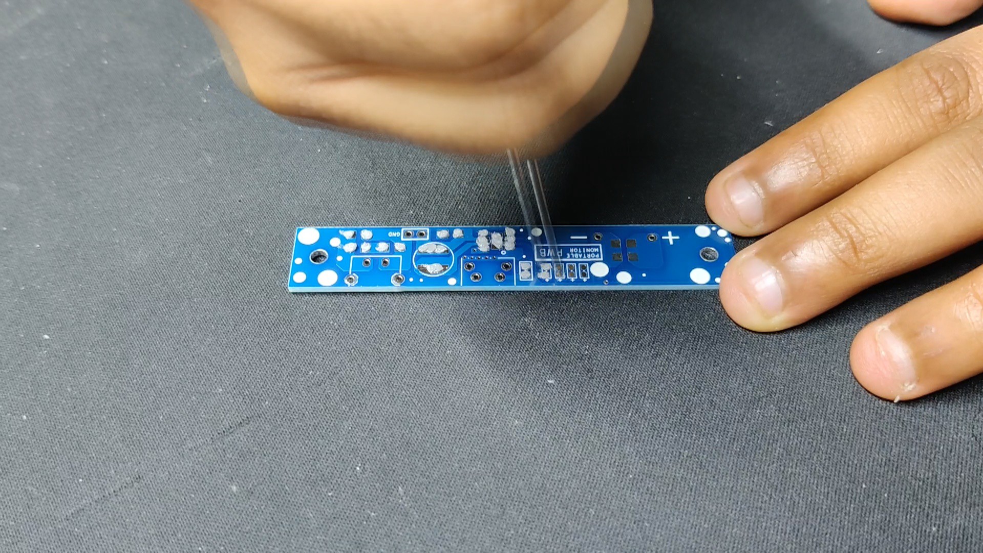
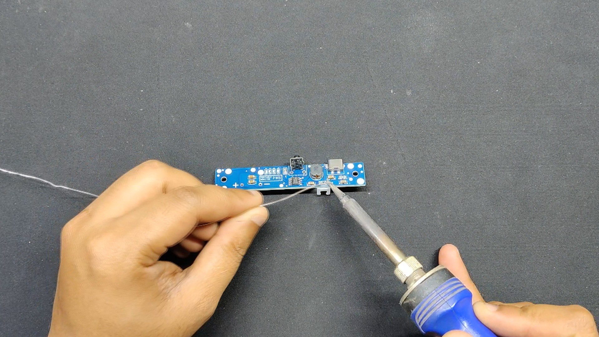
Next, we positioned every THT component—including the Type C port, the vertical push button, and the CON2 JST connector—in its proper location.
The soldering iron is then used to solder the pads of each THT component from the board's bottom side.
2
Power Source and Testing
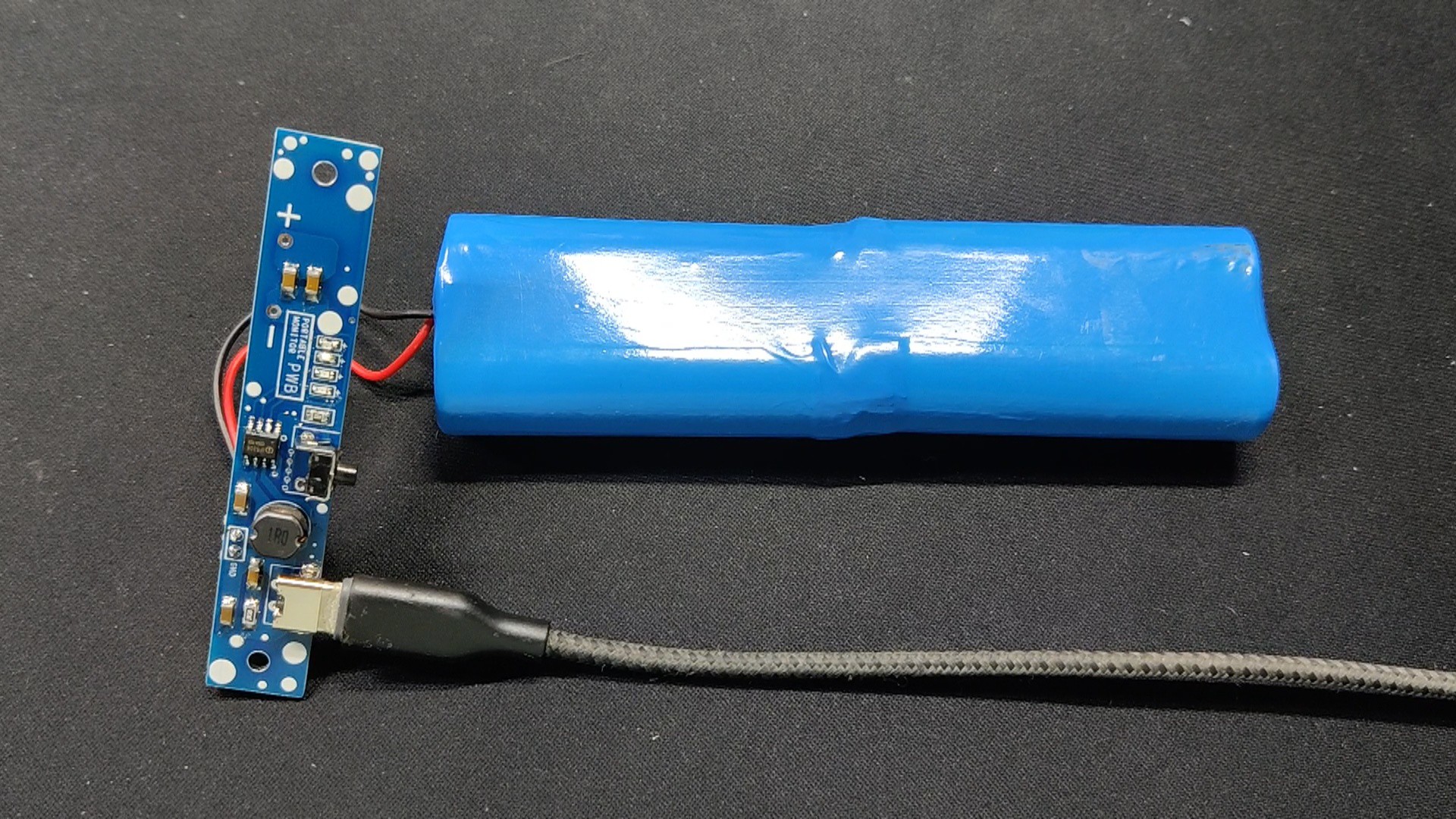
As the power source, we use a specially designed battery pack that has four 18650 3.7V lithium ion cells, each of which has a capacity of 2600 mAh. Since the display only requires 5V/1A, the 10400 mAh (38.48 Wh) total capacity that results from connecting all of the cells in parallel is enough to power it for more than seven hours.
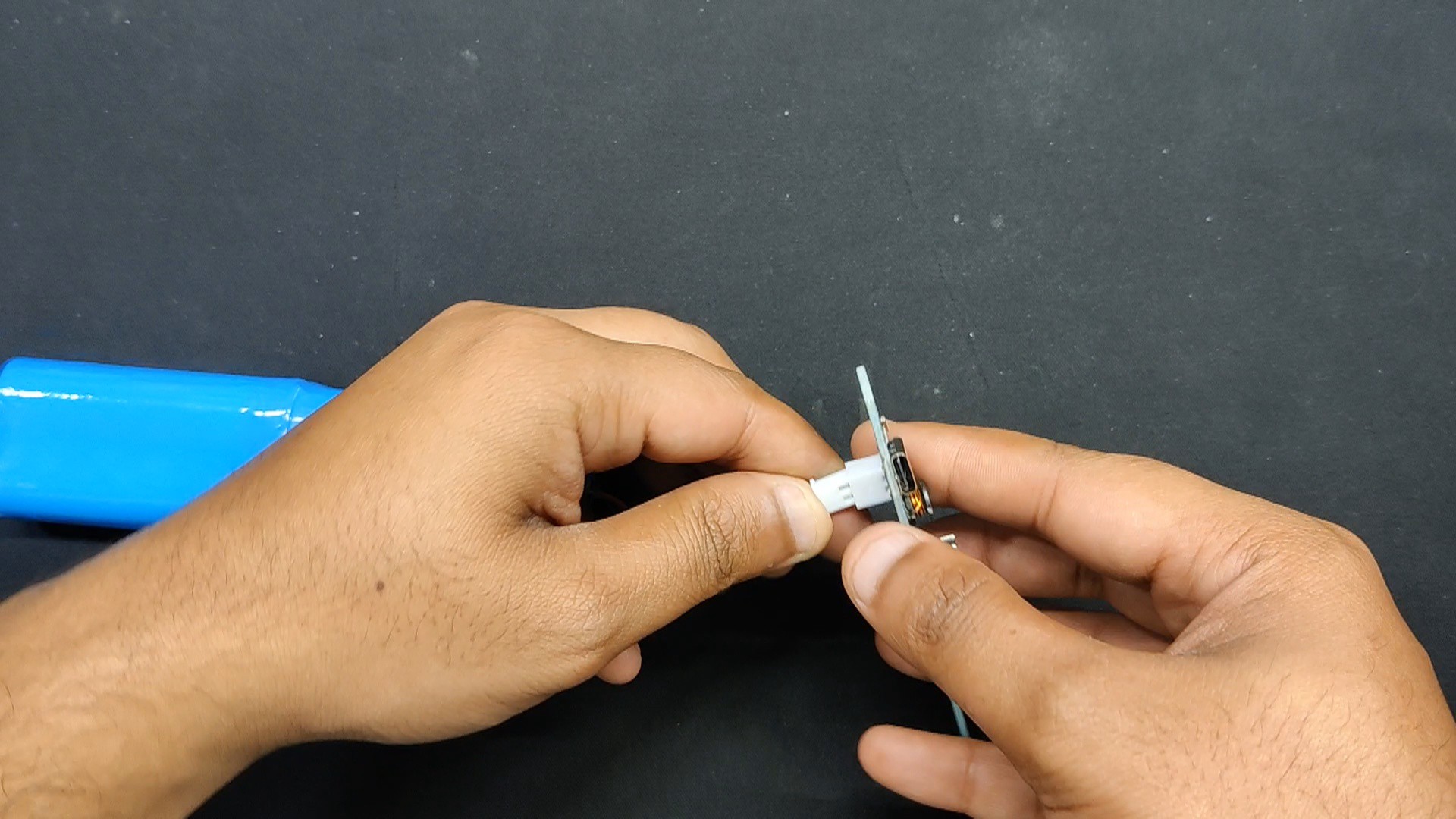
The battery's CON2 JST wire harness was linked to the CON2 JST connector that was added to the circuit.
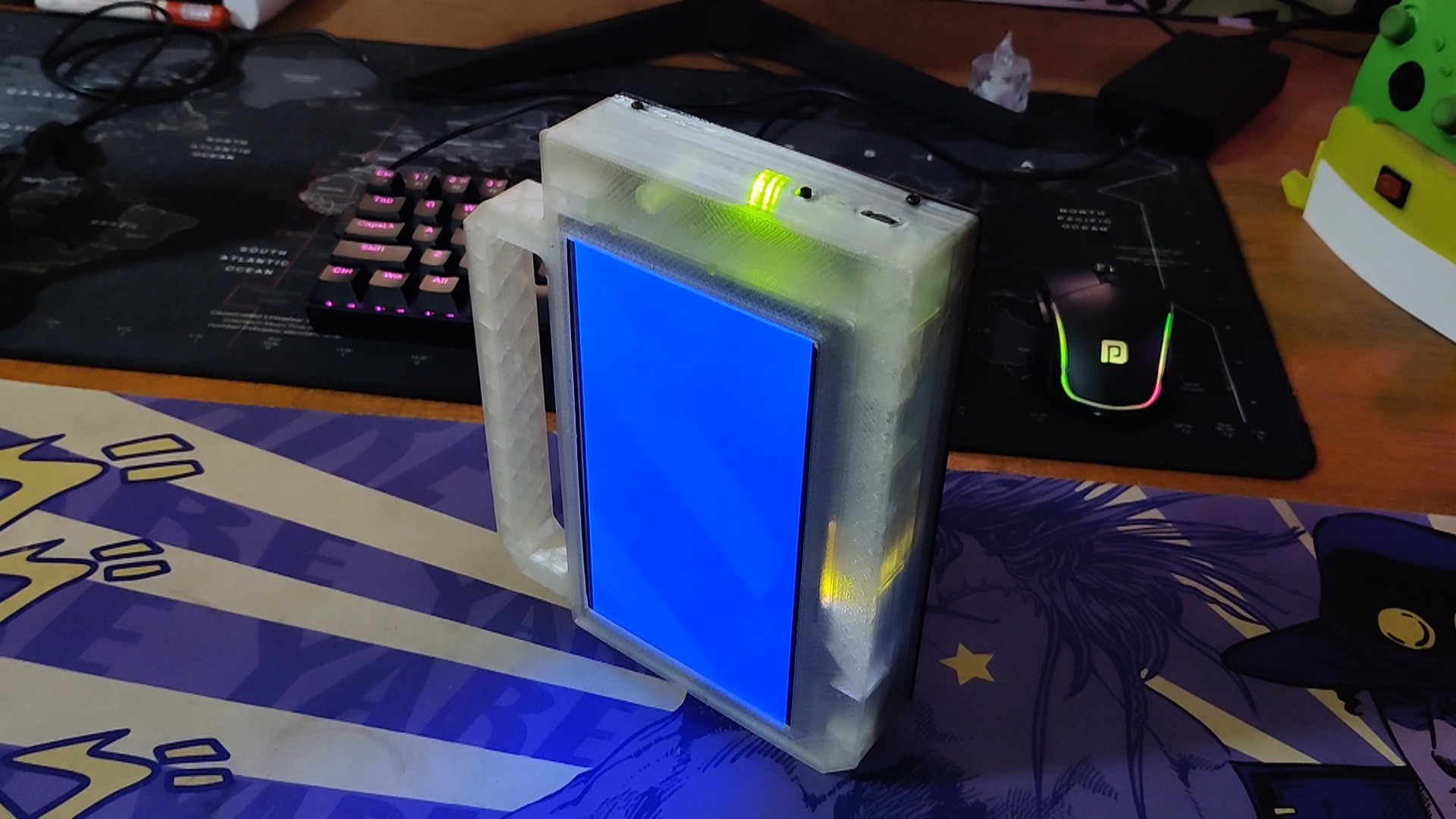
Upon pressing the Vertical Push button, the circuit is triggered, and the 5V output value of the power module signifies that the circuit is functioning.
Pressing the vertical push button twice will turn off the circuit.
We can also use this setup to connect a smartphone charger via the type C connector in order to charge the lithium-ion battery pack.
3
Display
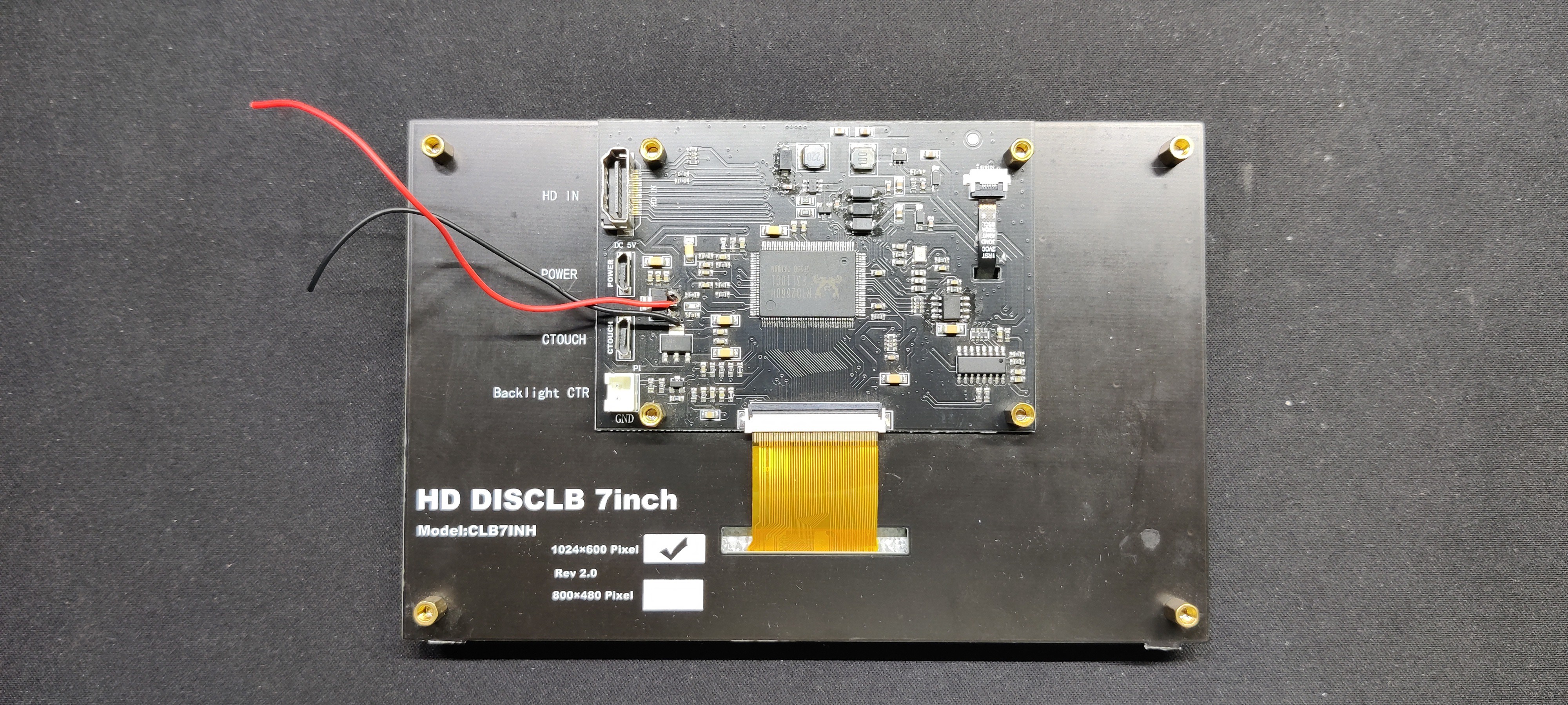
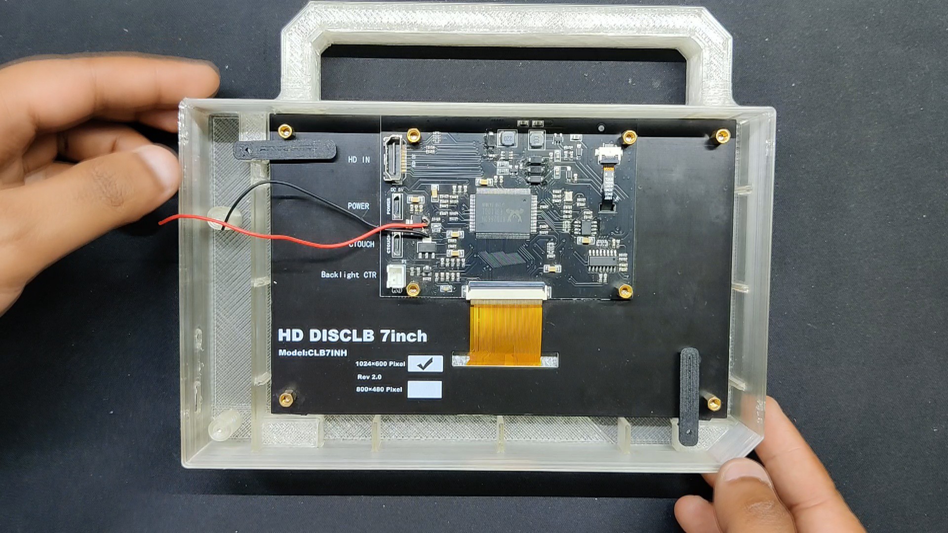
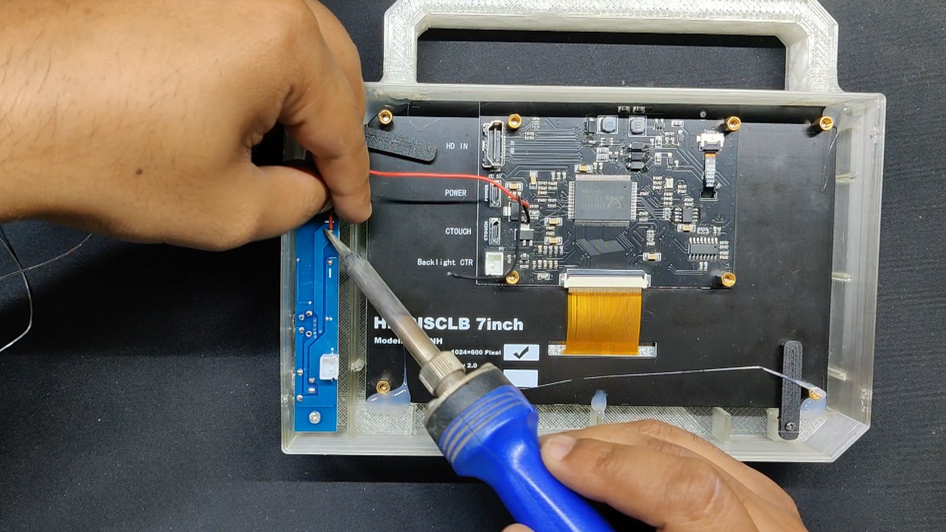
We are utilizing a typical 7-inch HD LCD panel with an HDMI input connection and an extra USB port that can be used to give it touch functionality. Since the display's touch is not very good, we will be ignoring this completely and concentrating just on the HDMI port.
The display has a resolution of 1024x600 pixels, is suitable for use with Raspberry Pi, NVIDIA, and Windows devices, and it weighs approximately 265 grams.
Additionally, it offers support for the Raspberry Pi as it contains four M3 PCB stanoffs onto which we can connect any Raspberry Pi exceot for the Zero Series.
4
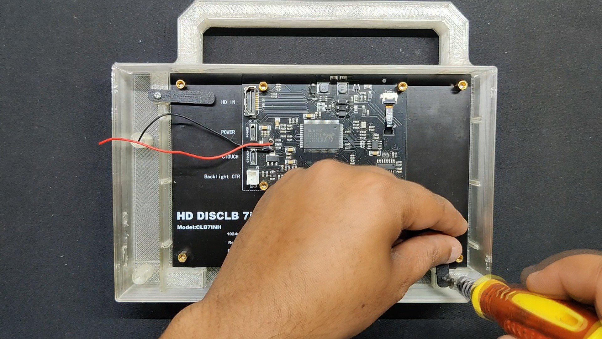
Frame Assembly
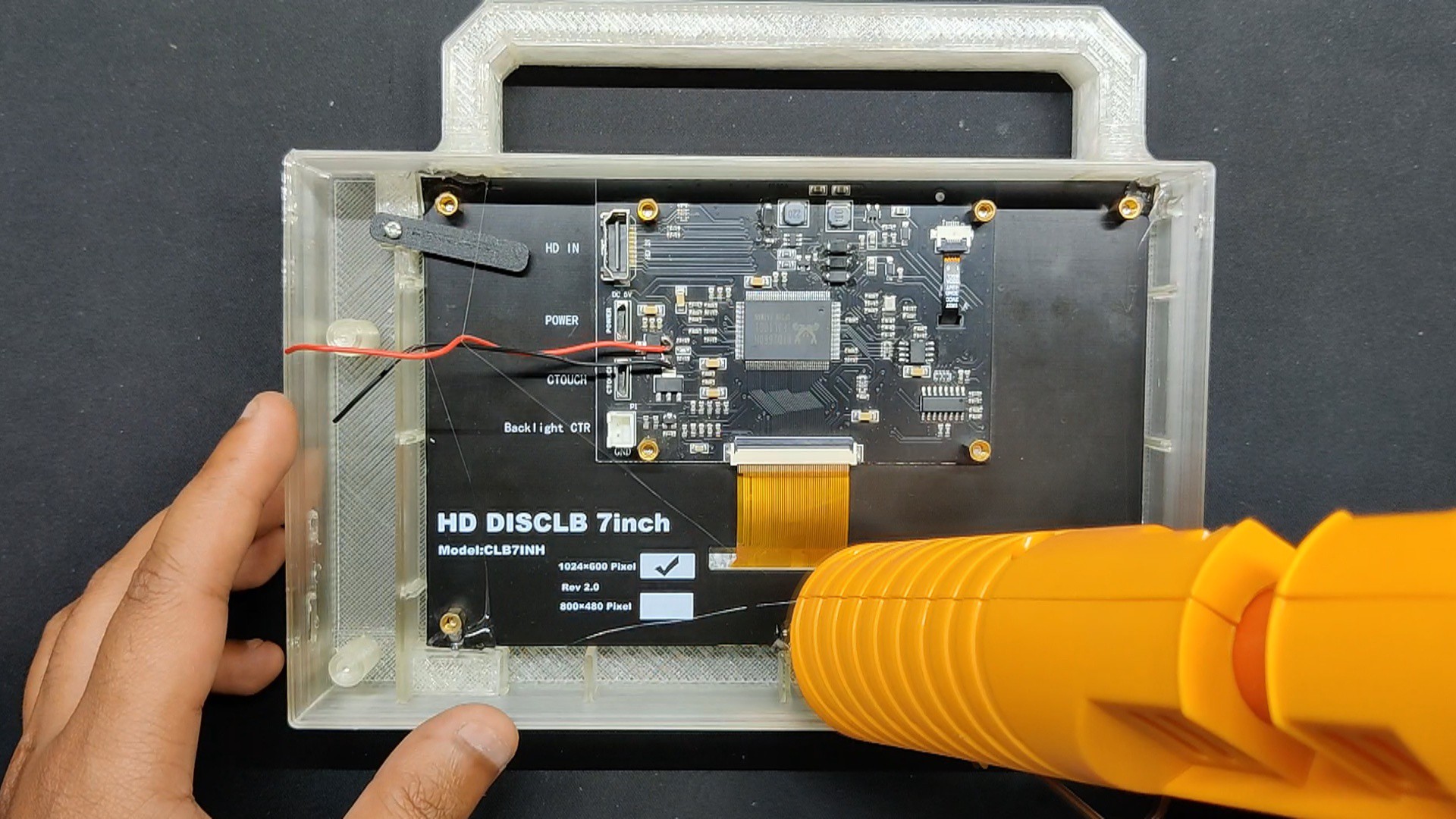
Placing the display in the designated display place inside the main body initiates the frame-building process.
Next, we install two screen holders inside the main body from both sides. These screen holders are fastened to the main body with two M2 screws and will hold the display in place.
In order to ensure that the display stays in position and is permanently secured to the main body, we also applied a little amount of hot glue to its corners.
5
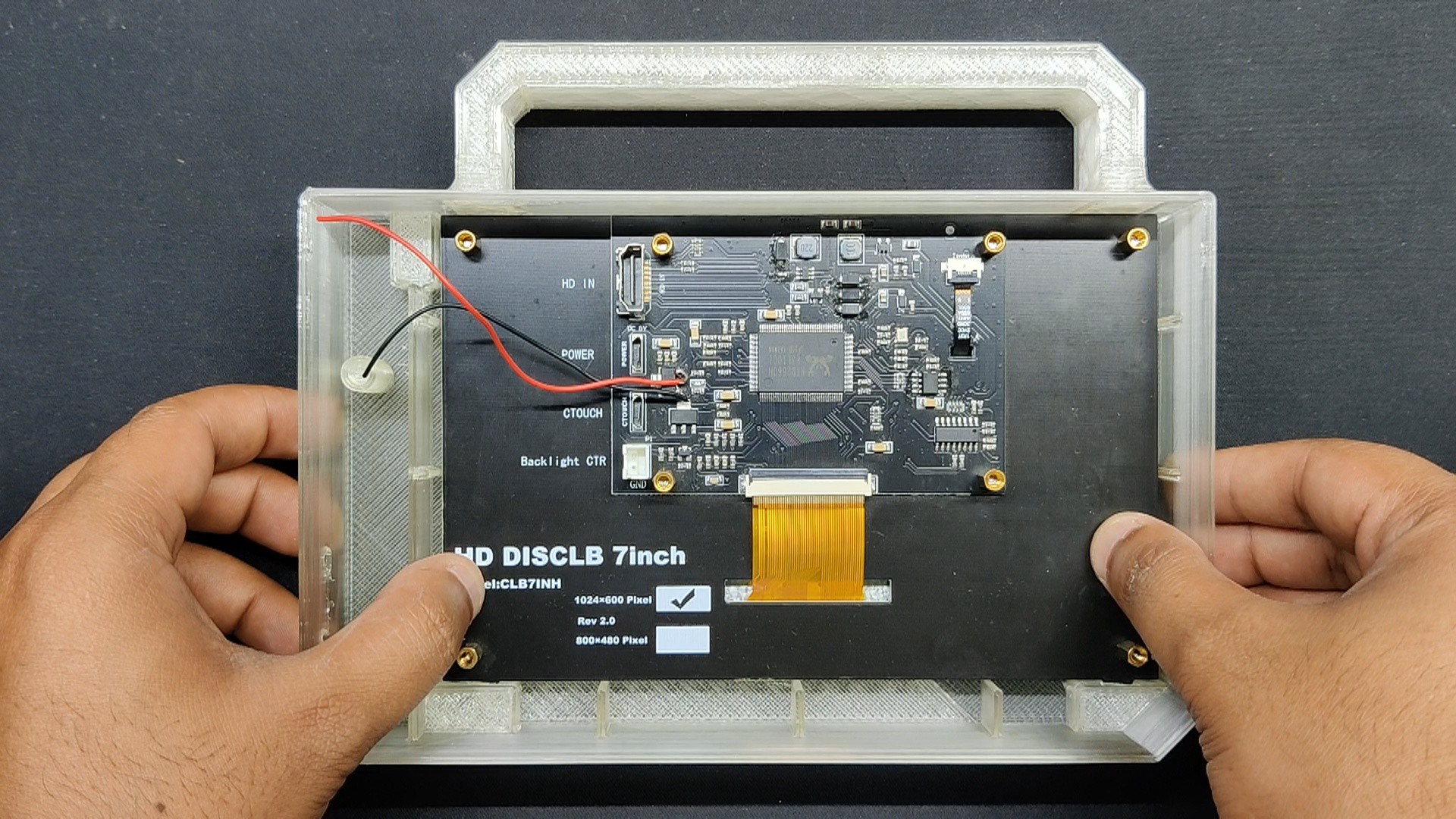
Circuit and Frame Assembly
Now that the circuit is positioned over the two screw bosses, we mount it there using two M2 screws
6
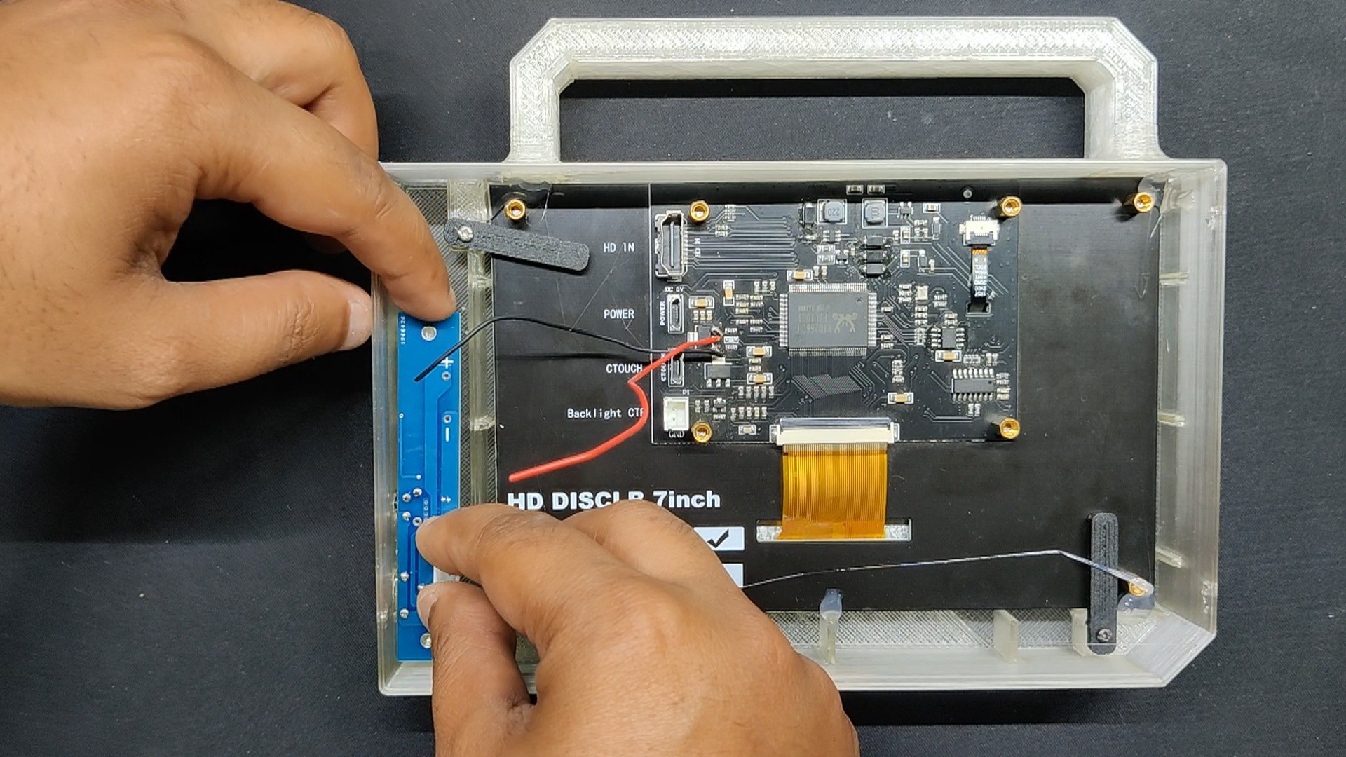
FINAL ASSEMBLY
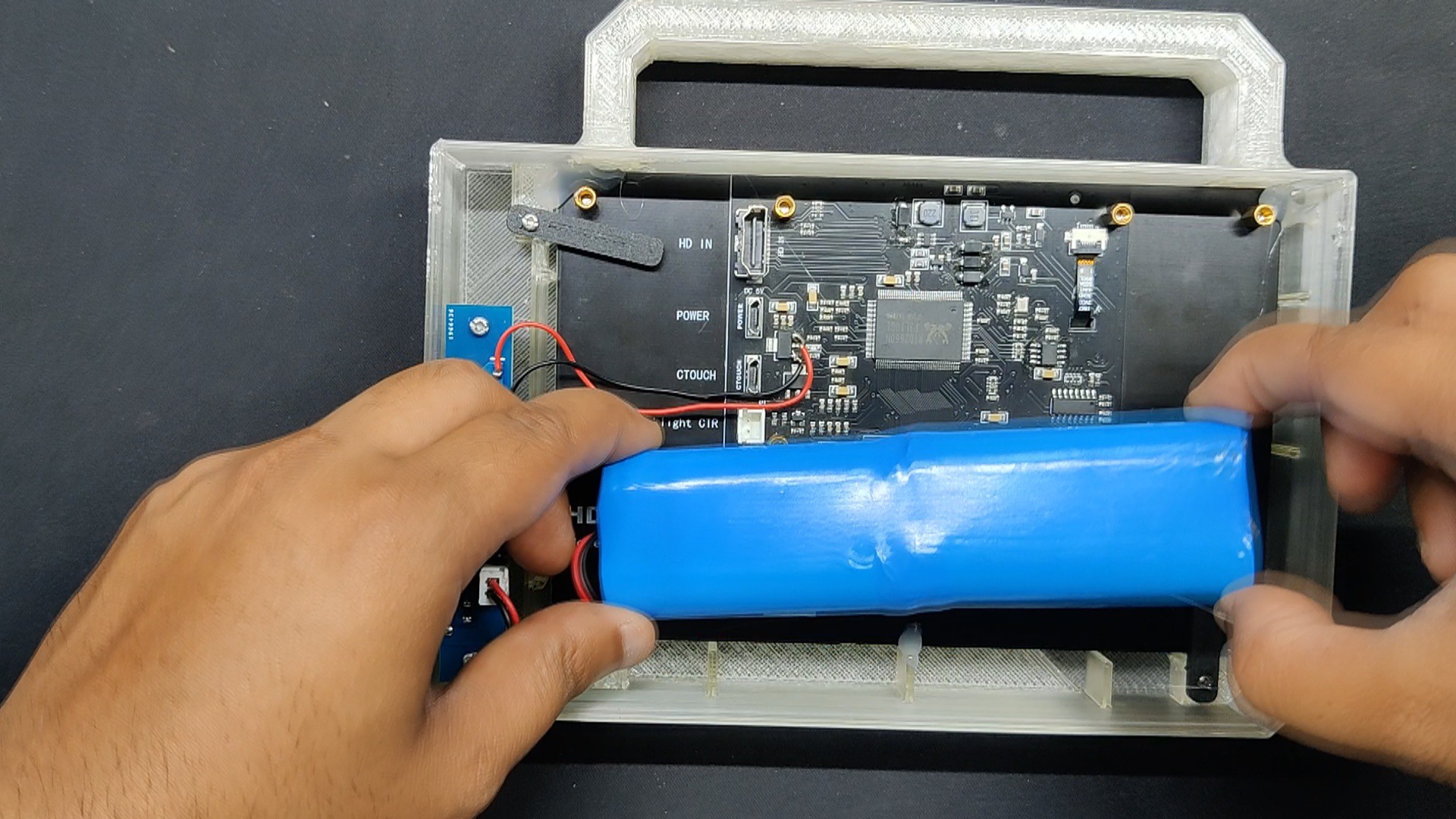
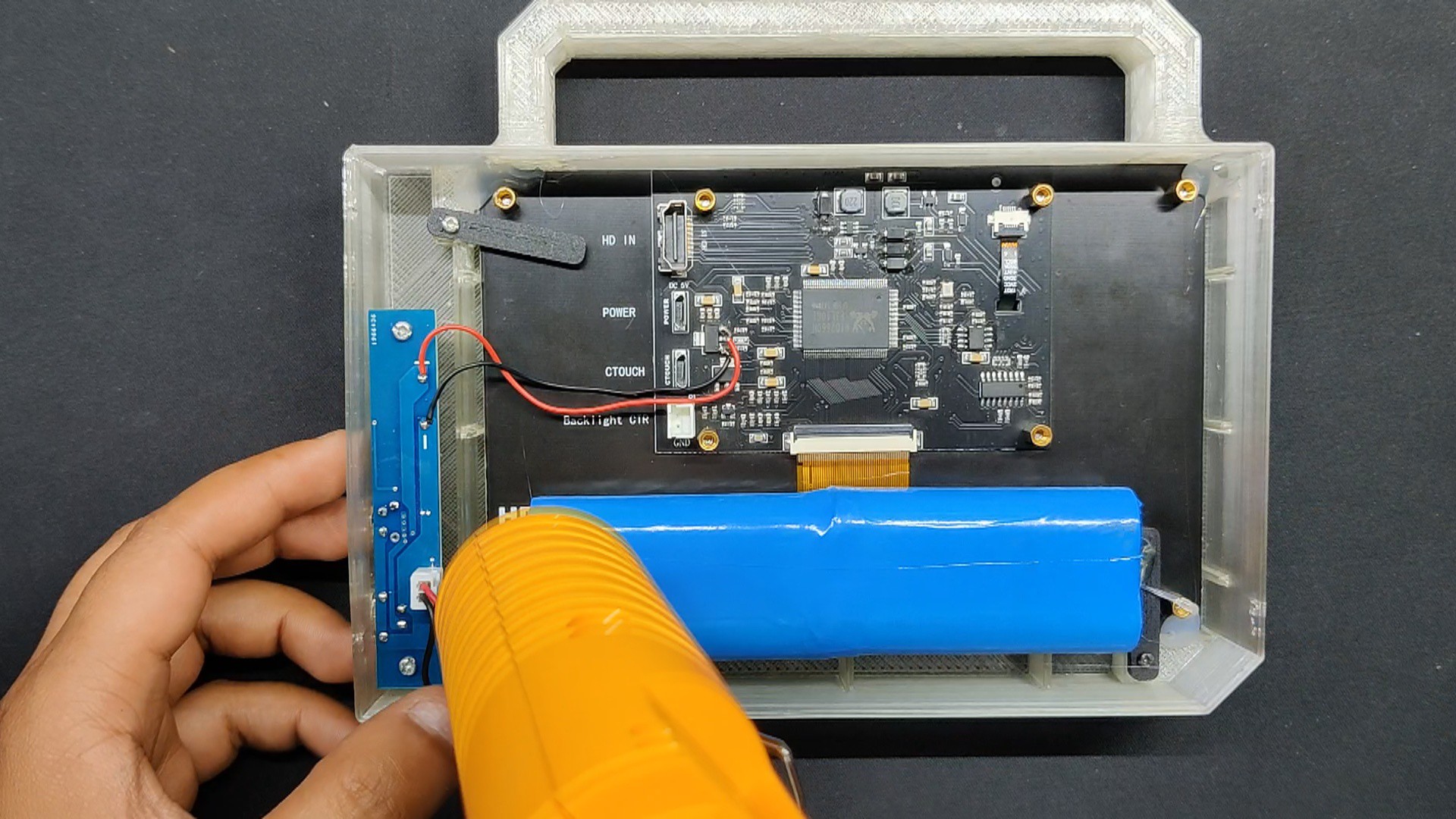
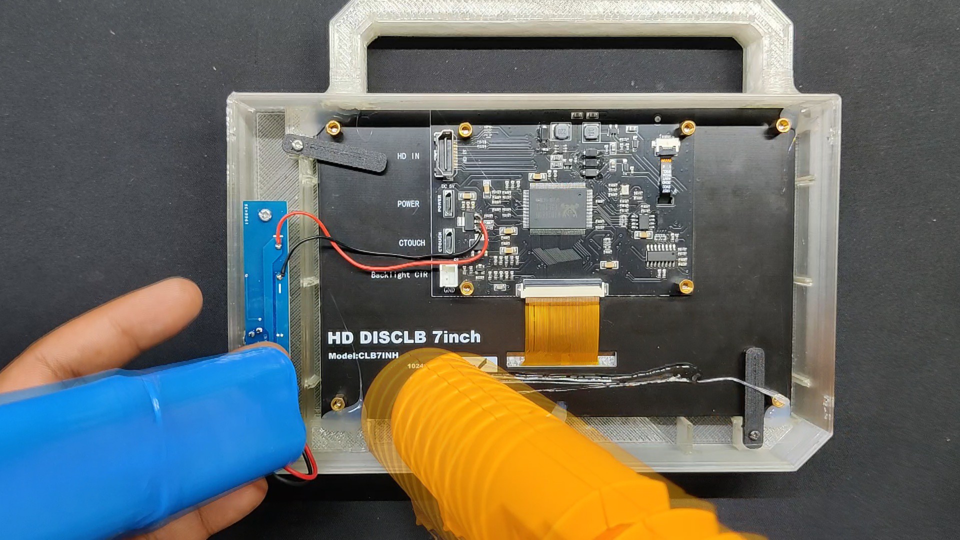
The power board's output terminals are now connected to the display's input terminals; the power board's 5V is connected to the display's 5V IN.
The power board's GND and the display's GND are connected.
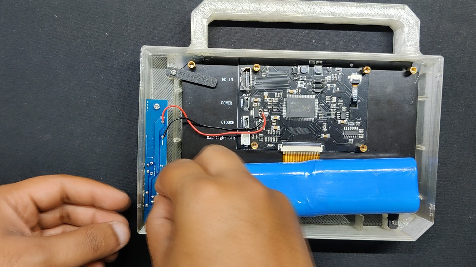
The battery is then connected to the power board by connecting the battery's JST connector harness to the JST connector on the circuit board.
We use a tiny bit of hot glue on the screen to mount the battery, which holds it securely in place.
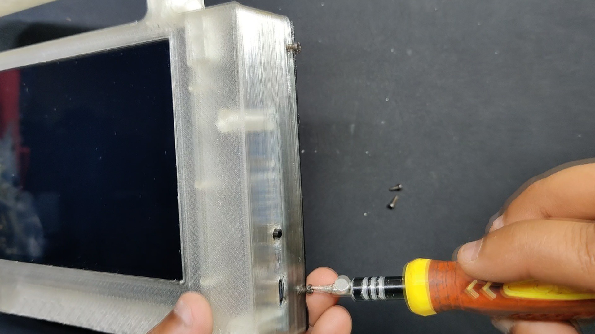
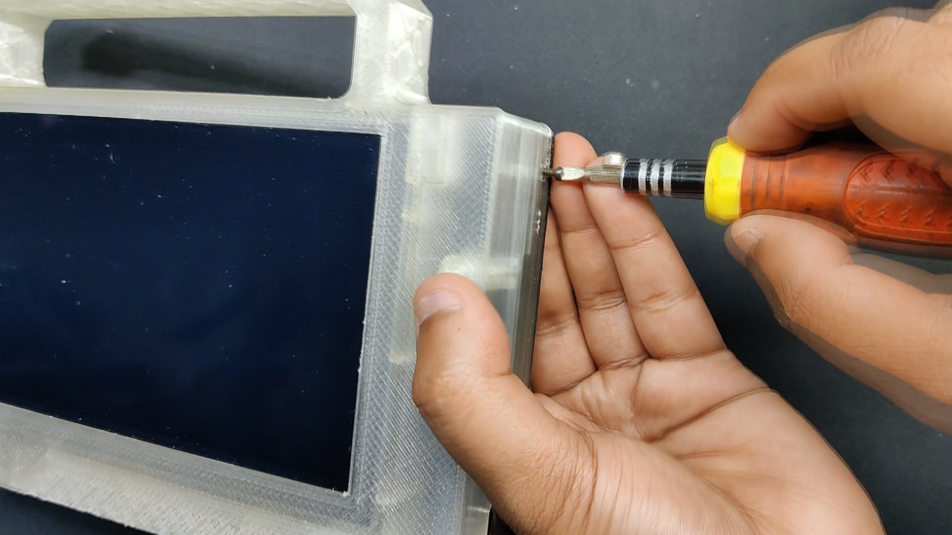
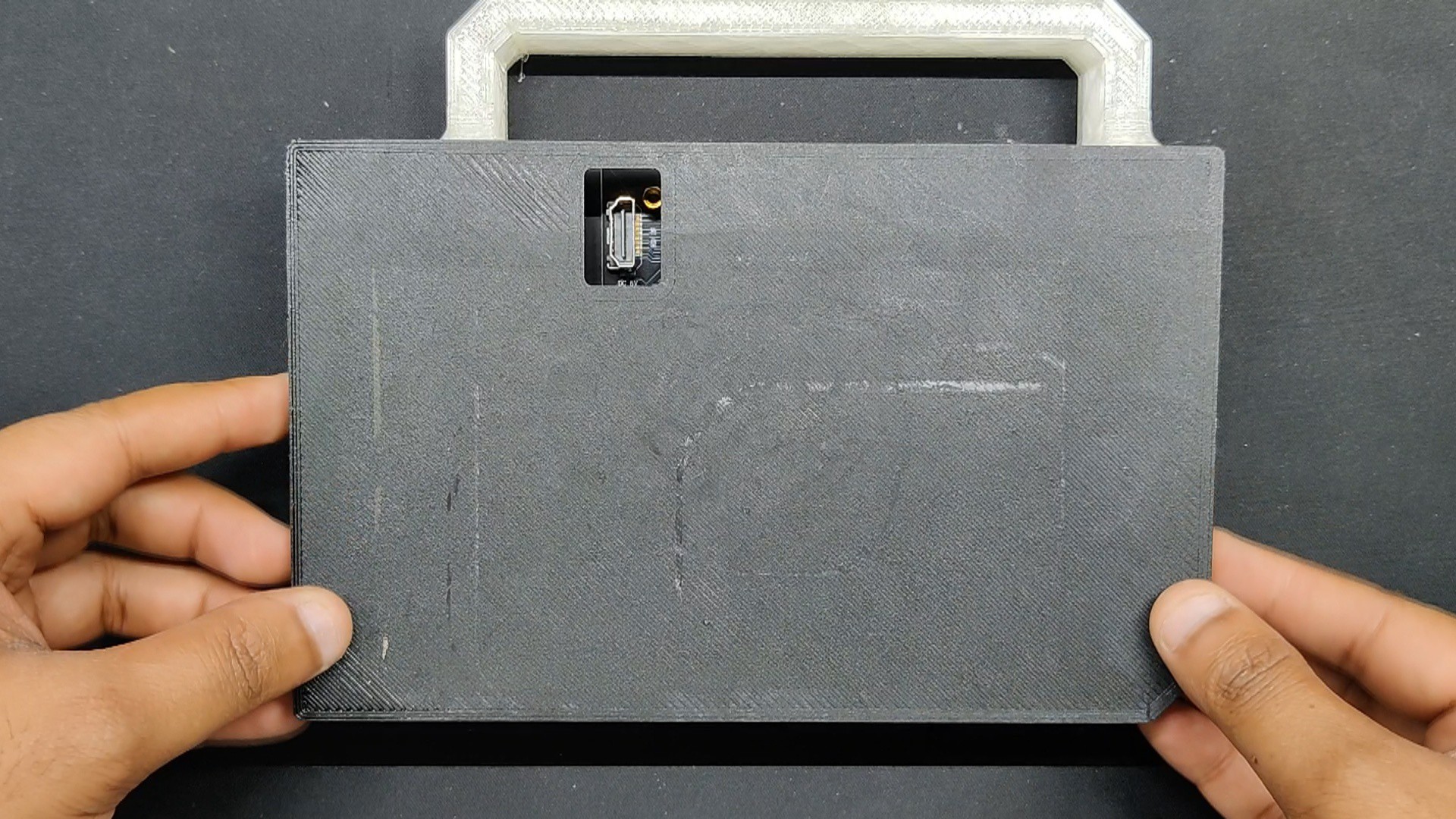
Finally, we put the cover on the backside and fasten it with four M2 screws.
7
Result
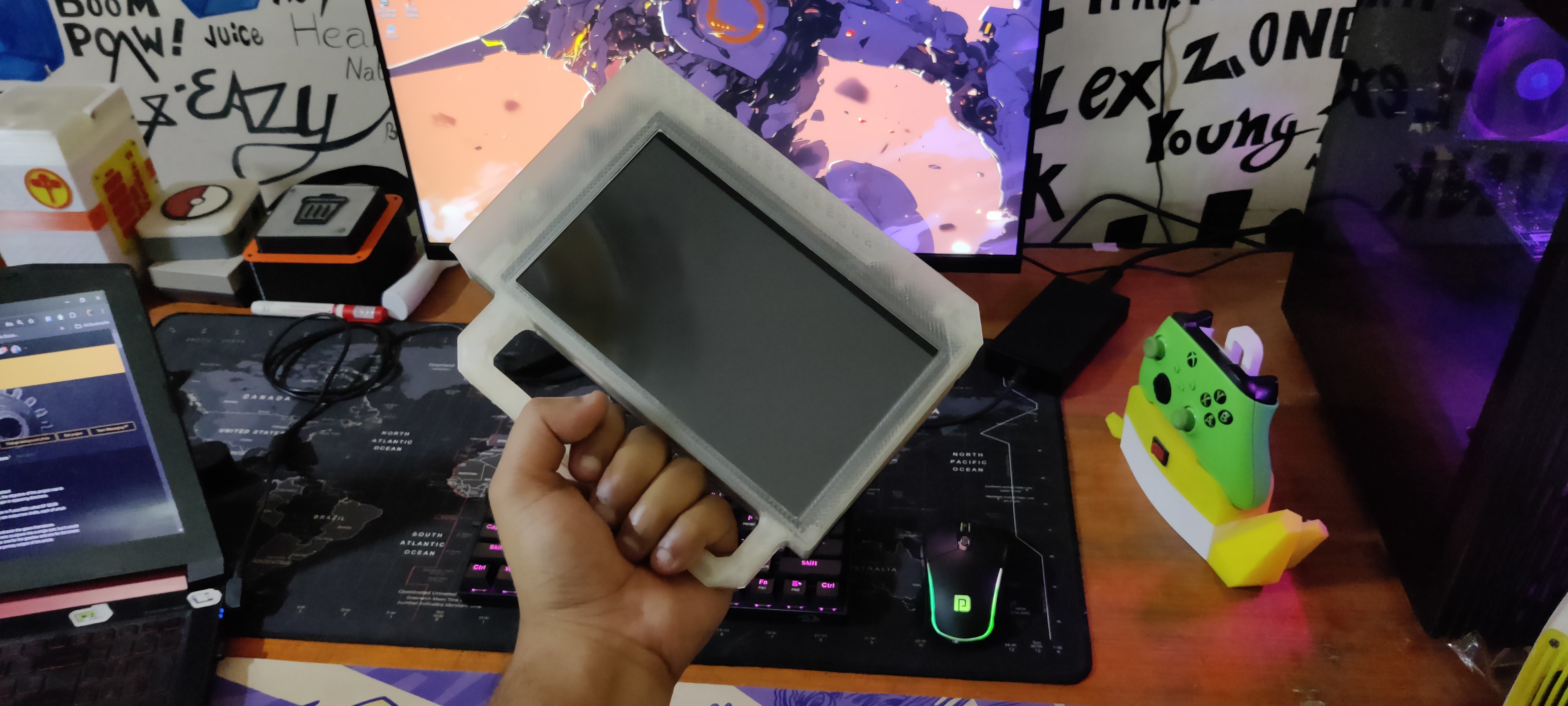
Here is the end result of this straightforward build: a functional portable monitor that runs on its own power sources and is portable; all it needs is an HDMI connection.
This device turns on when the push button is pressed once, and it shuts off when the push button is double-pressed.
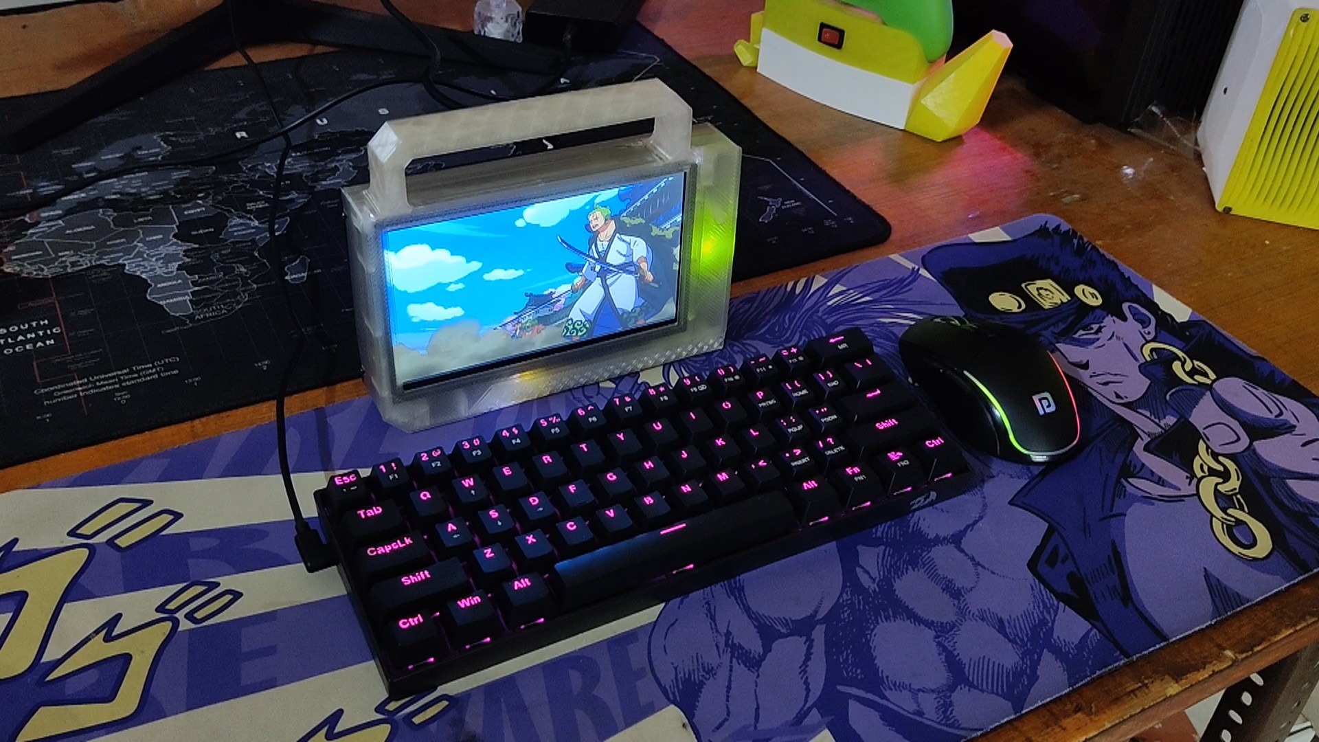
This display is basically a small monitor that can be used as a main monitor for any single-board computer, an additional monitor for our desktop setup, or a portable monitor that we can carry around and use as our laptop's second screen. We connected it to the HDMI port on our desktop and played One Piece on it.
Overall, this display appears to function fairly well and has a runtime of more than seven hours, which is fantastic. However, we need to address the display's thickness in the next version. It is currently 25 mm thick, which is not very thick, but we can reduce it by using a Li-Po battery pack rather than a Li-ion one, which will also reduce thickness, and by replacing the current display with a slimmer one.
All the details regarding this project, including files, are attached, which you can download.
Leave a comment if you need any help regarding this project. This is it for today, folks.
 Arnov Sharma
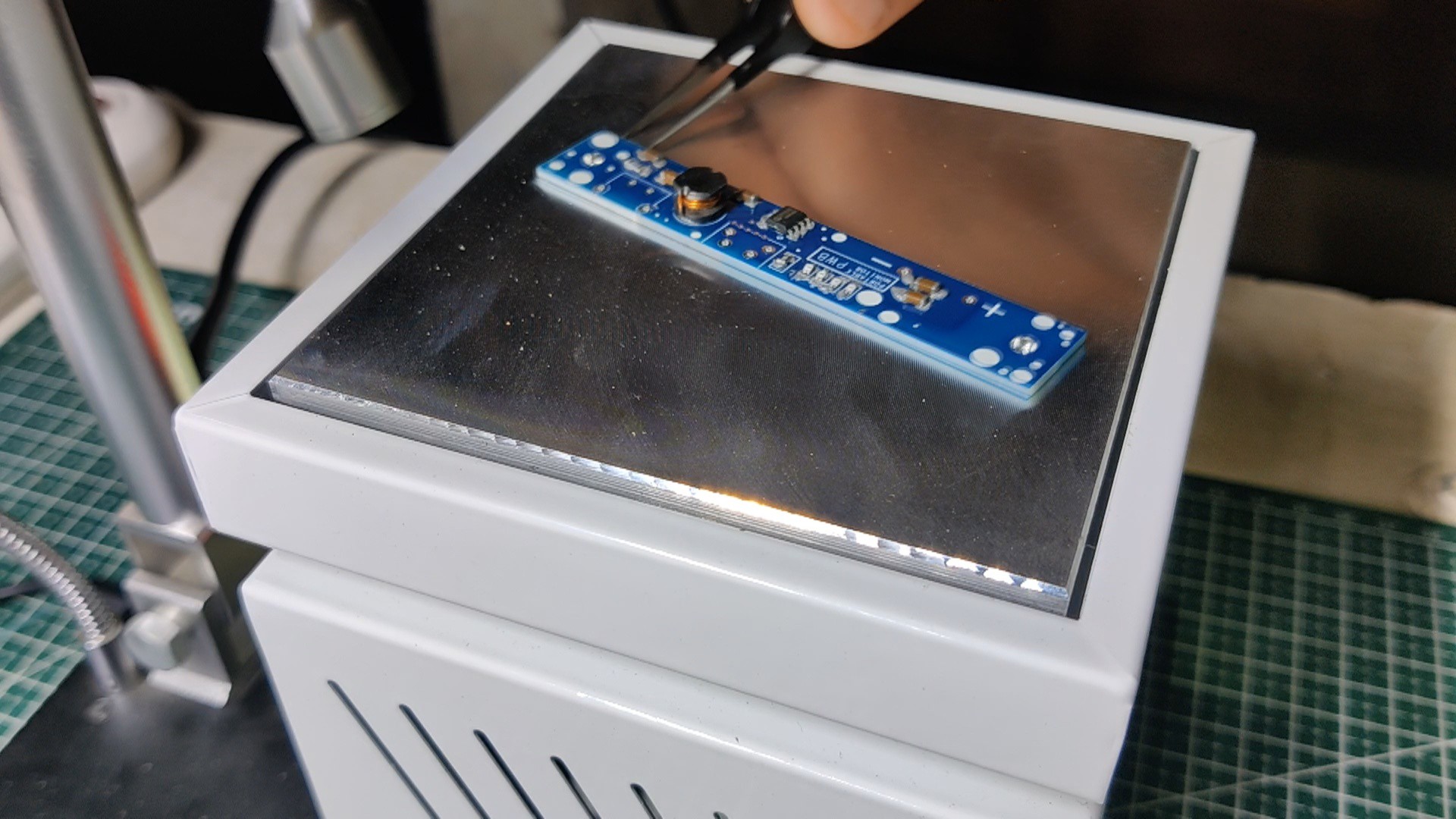


Discussions
Become a Hackaday.io Member
Create an account to leave a comment. Already have an account? Log In.