 Arnov Sharma
3D Design

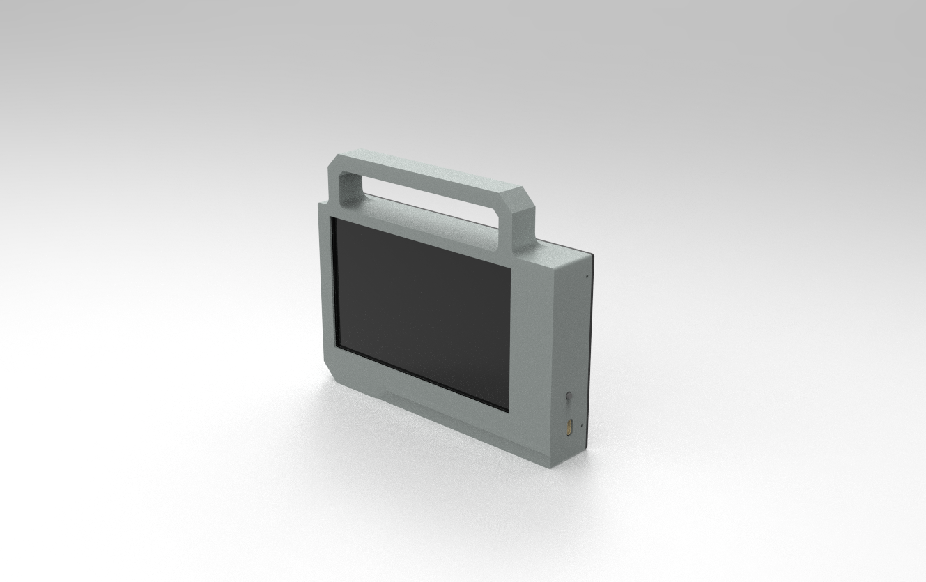
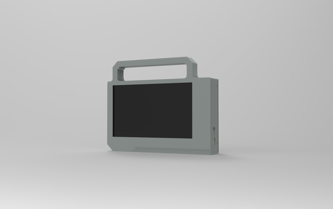
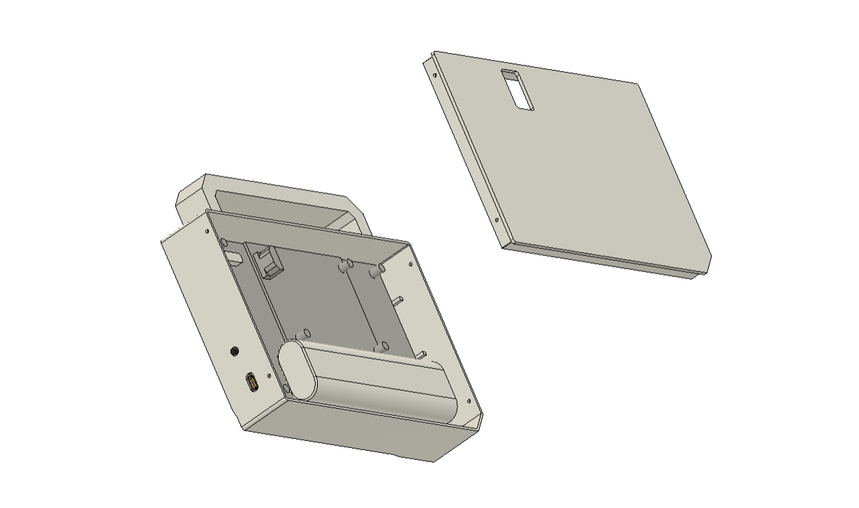
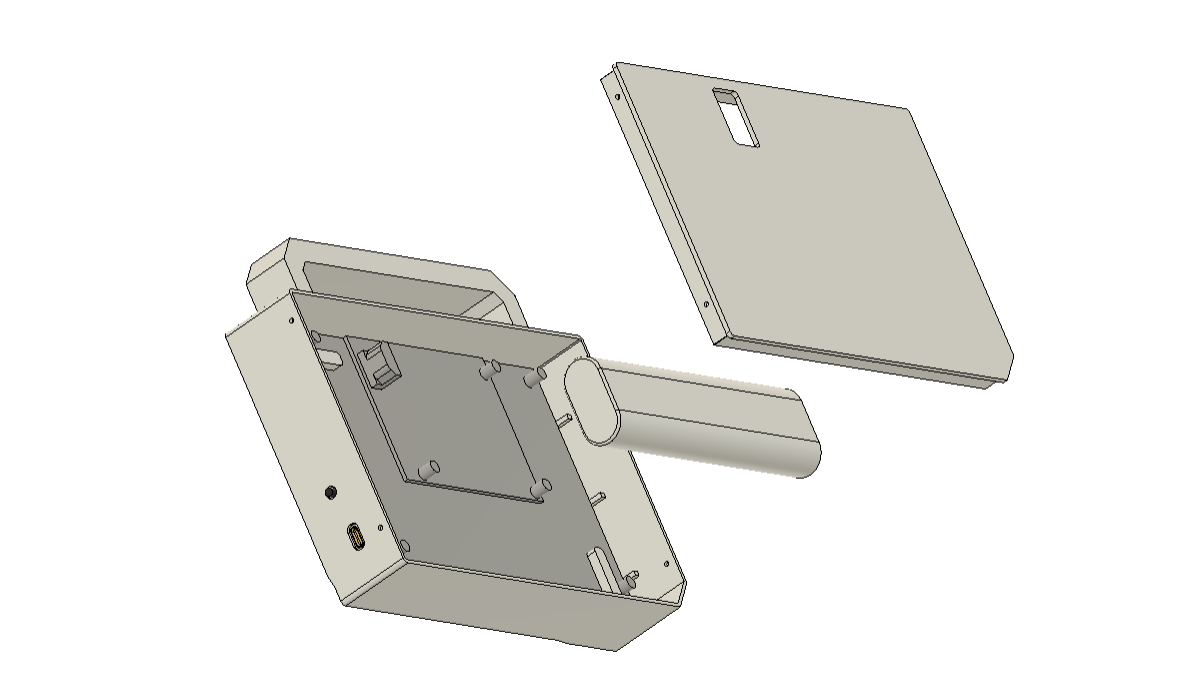
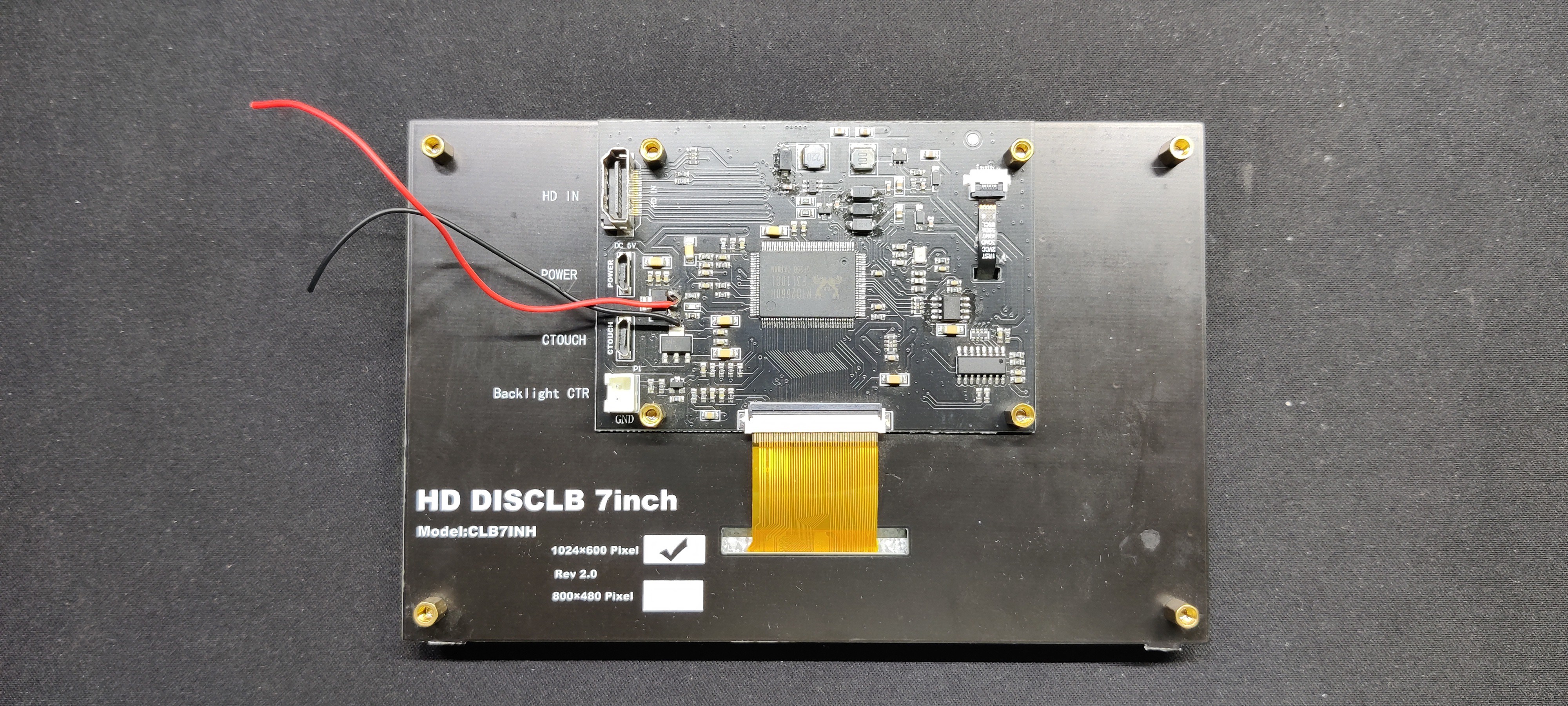
The main body and the lid are the two primary components of this project's 3D design. The main body houses the display, circuit, and battery. The lid portion is used to cover the rear and has a slot or opening that enables the user to connect an HDMI cable to the display's HDMI port.
In order to create a rectangular box-like shape, we first imported the display's model into the design and then created the main body so that the entire assembly revolves around the display, which is held in place.
To keep the display in place, we also built two display holding components.
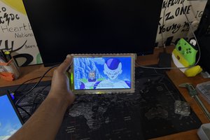
On top of the main body, we incorporated a handle-like component that can be used to carry or raise the entire portable display, much like a briefcase.
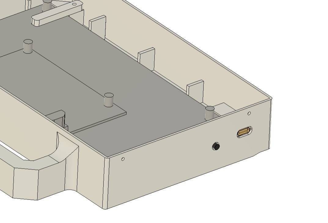
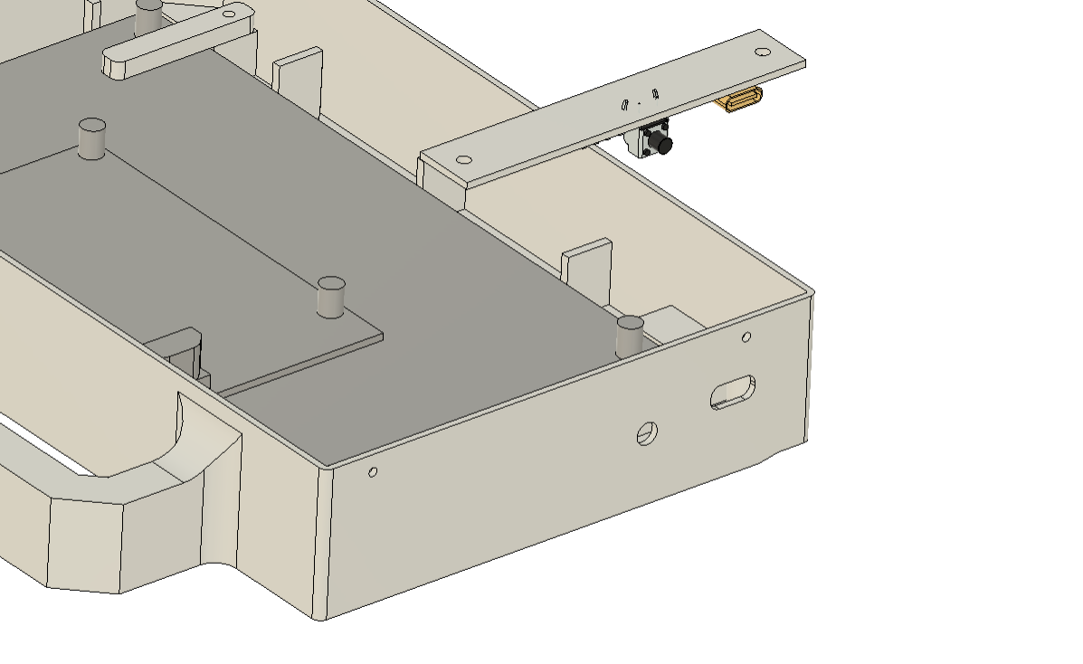
The circuit, which consists of a PCB with the Type C port and the vertical push button on it, is modeled from the ground up. Two screw bosses are being used to mount the circuit close to the display. M2 screws will be used to fasten the circuit to the bosses.
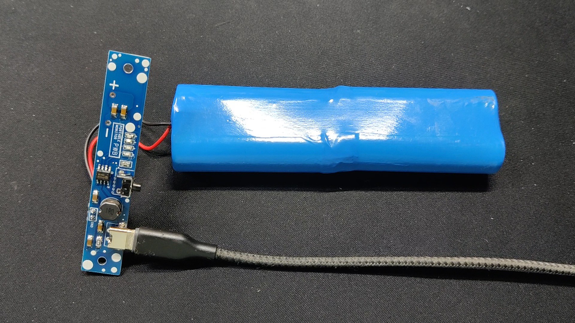
Additionally, the battery was designed and placed on the rear of the display; hot glue will be used to hold the battery in place inside the portable display.
Following model completion, we exported all of the files as mesh files and 3D printed them on our Ender 3 printer, using transparent PLA for the main body and black PLA for the screen holders.
Circuit-Power Board
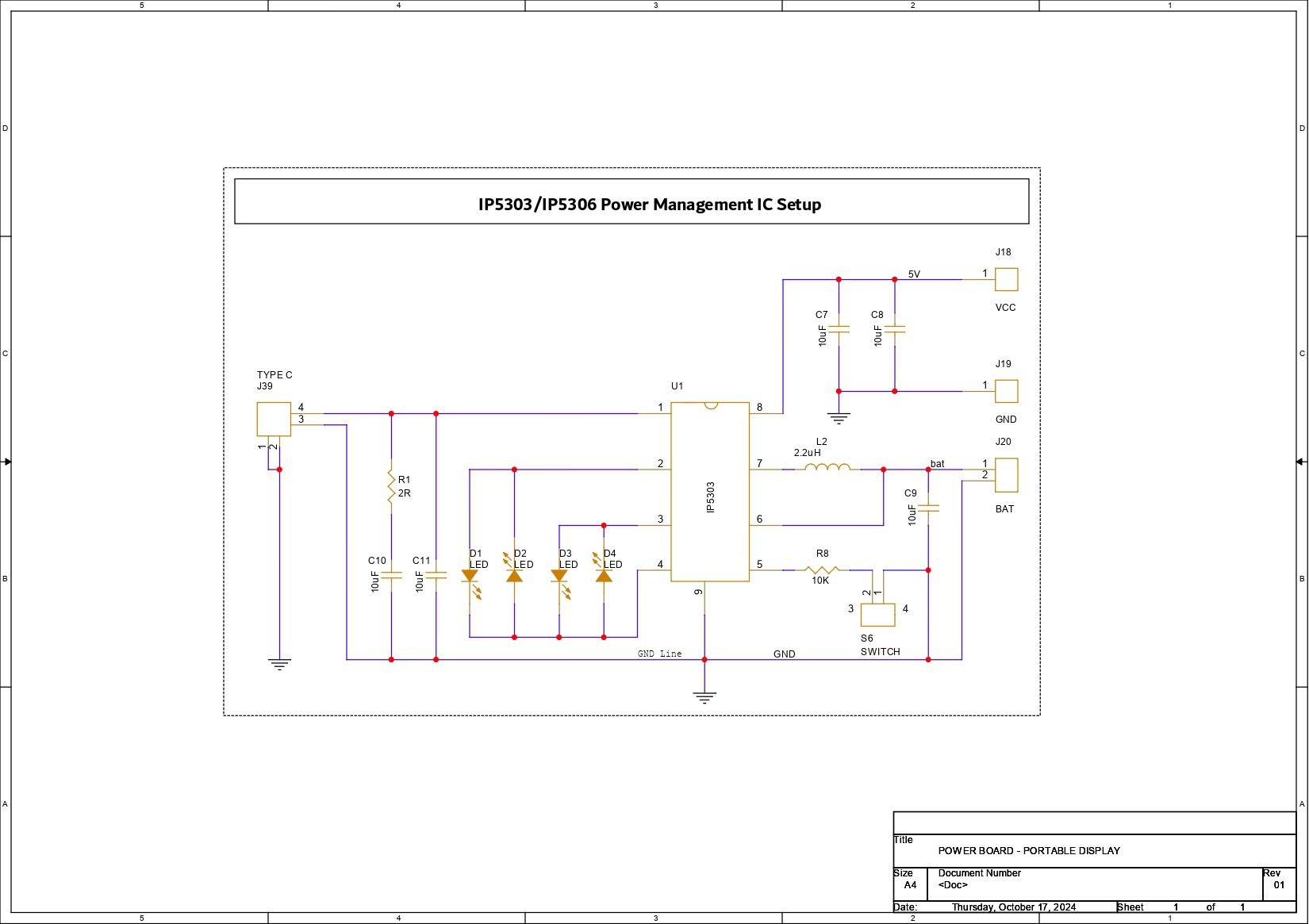
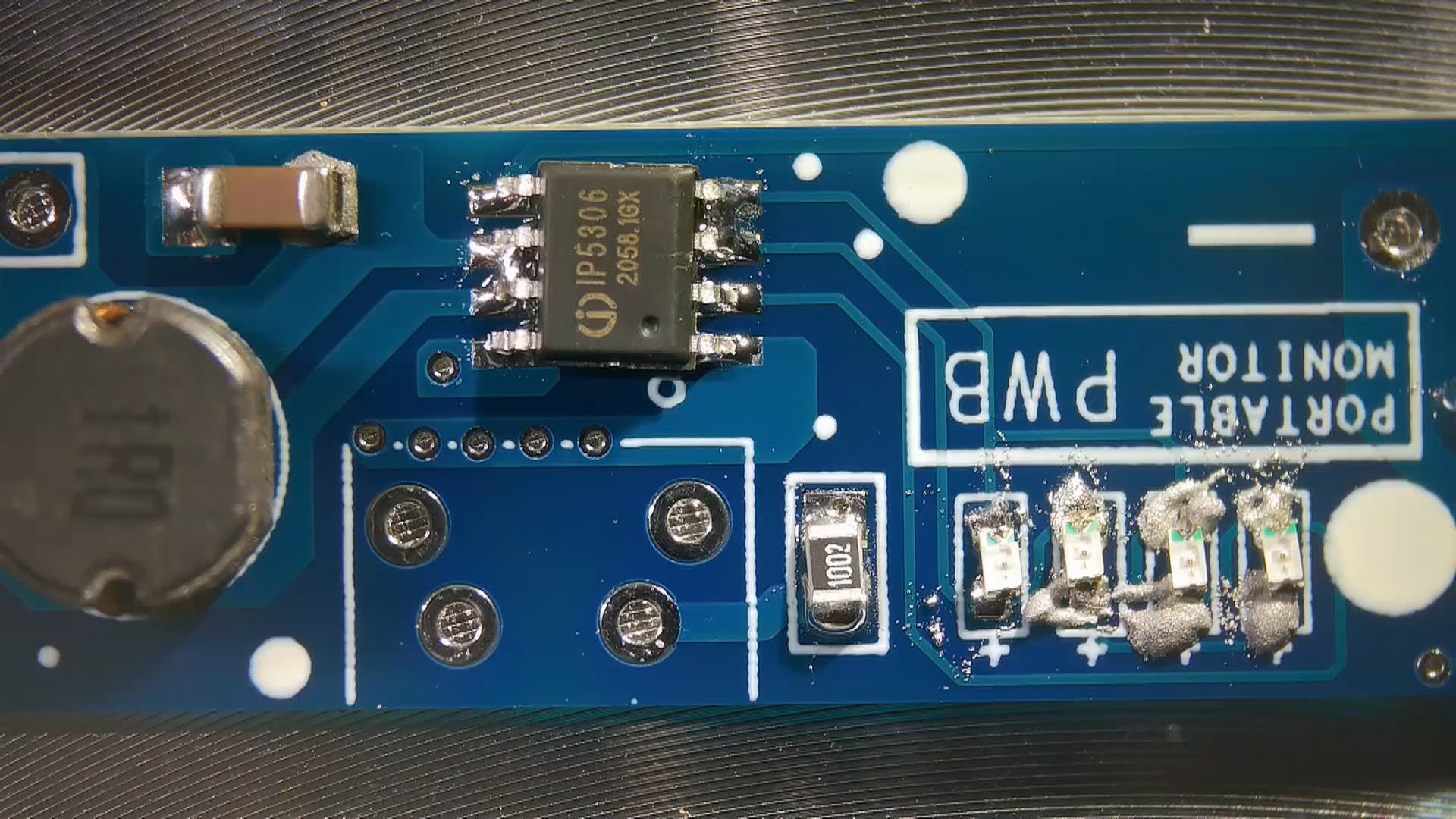
The IP5306 Power Management IC, which supplies a steady 5V 2A of power from a 3.7V Li-ion source, was included in the project's schematic. Its high-cut and low-cut features protect against overcharging and overdischarging the cell.
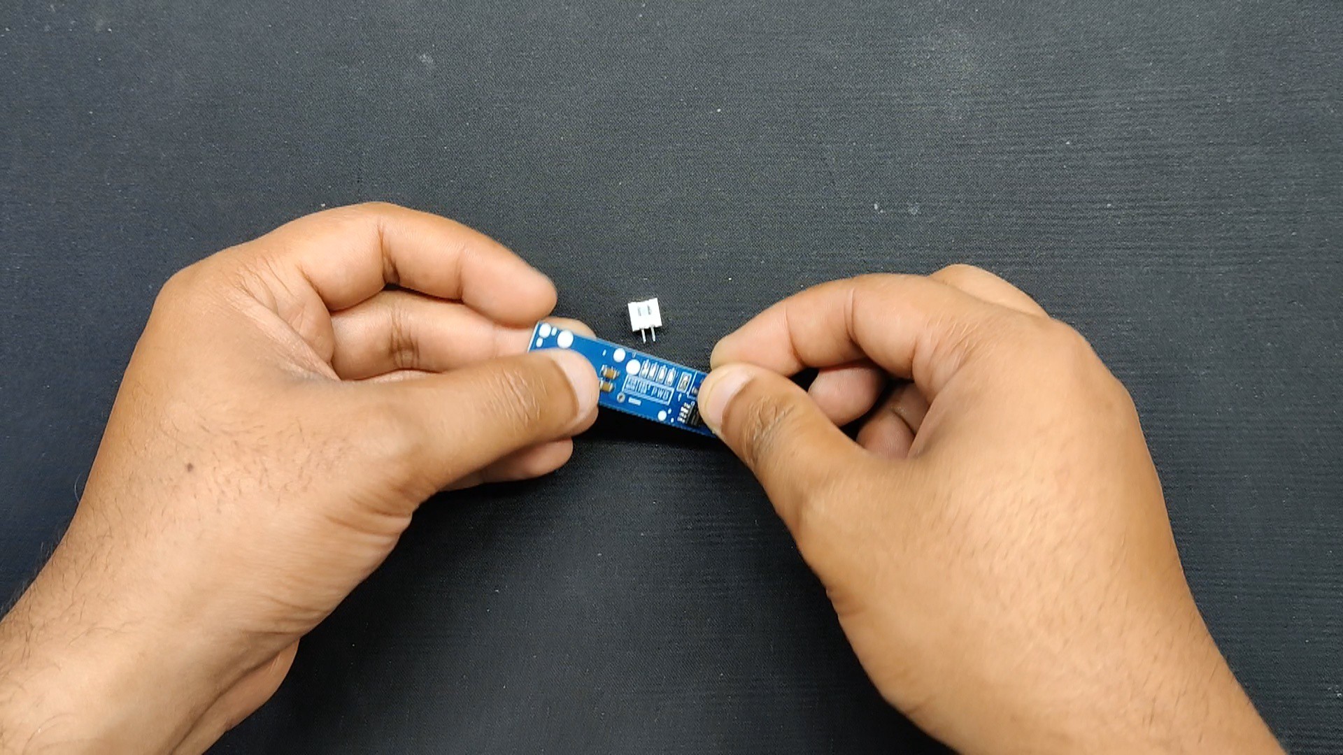
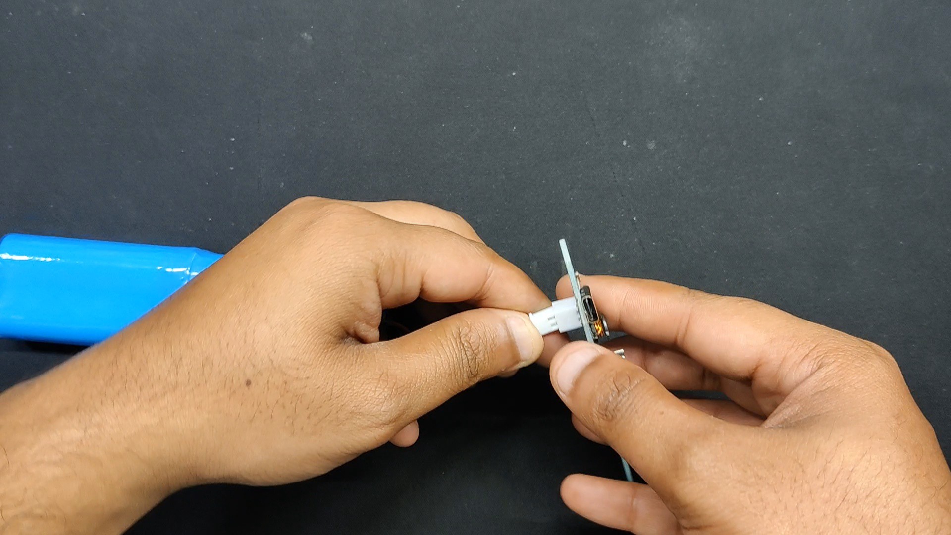
The charging port that we are employing is a Type C through-hole port that positively connects to the IC's charging port. Along with the charging port and GND, we added a 10uF filter capacitor and a 10uF capacitor combination with a 2Ohm resistor.
Additionally, four LEDs—which will serve as battery-full indication LEDs—are added to the IC's LED port.
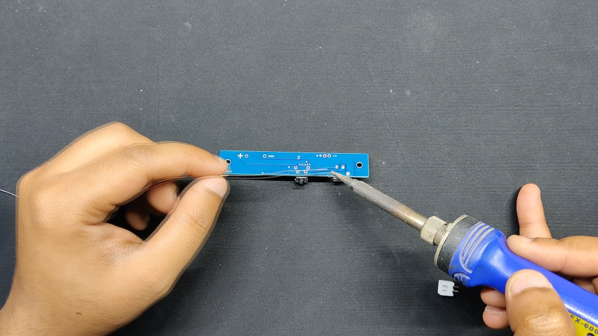
To turn this device on and off, a push button has been added.
Additionally, we added two extra filter capacitors to the IC and GND outputs.
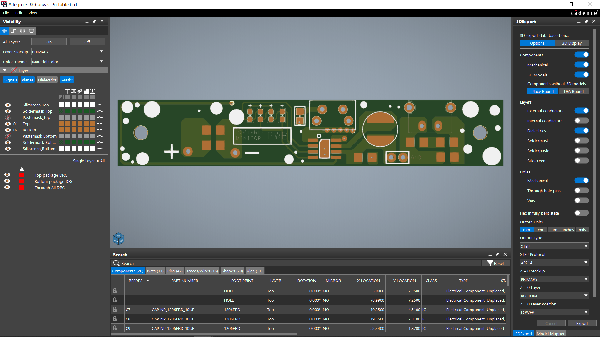
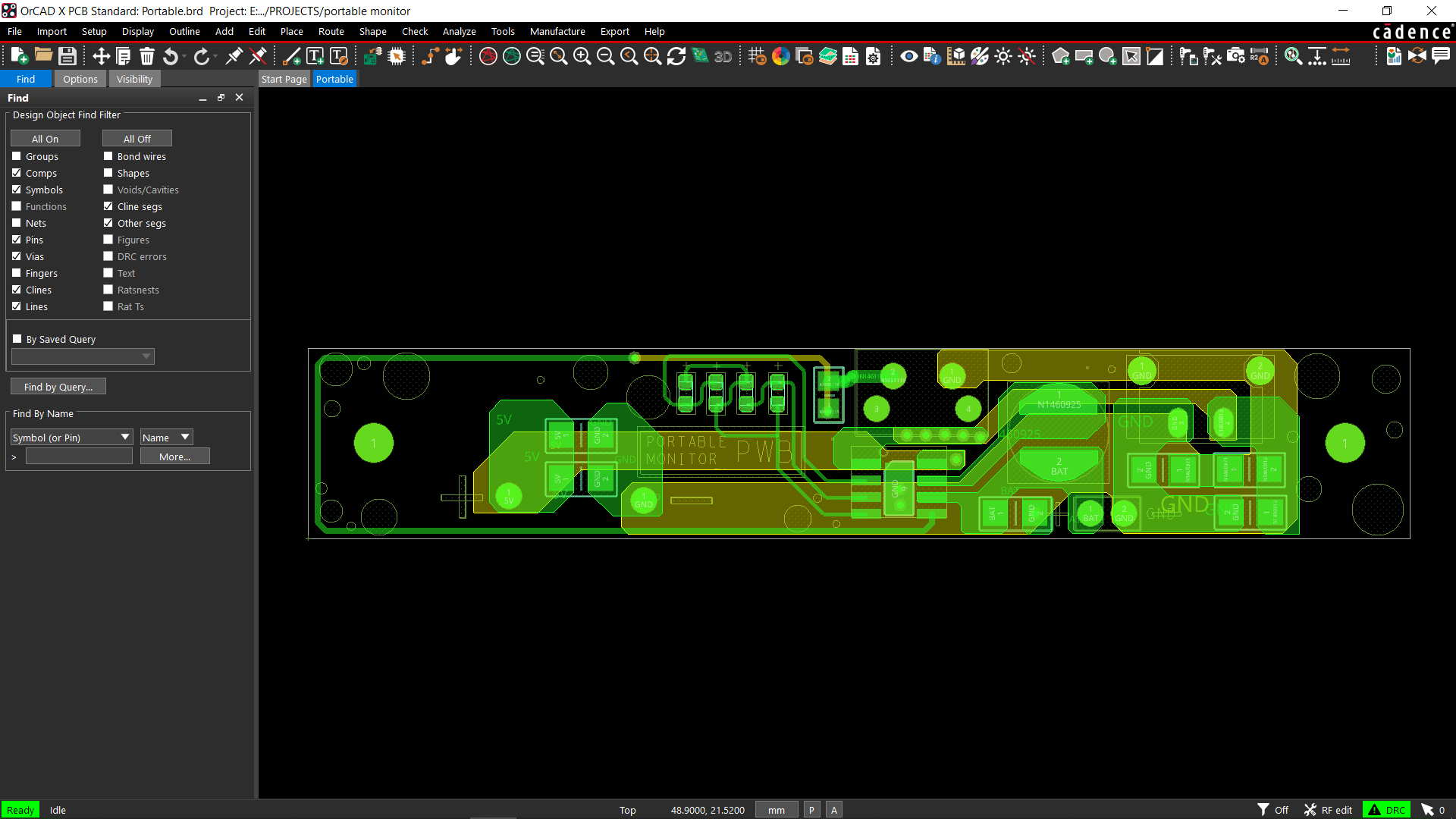
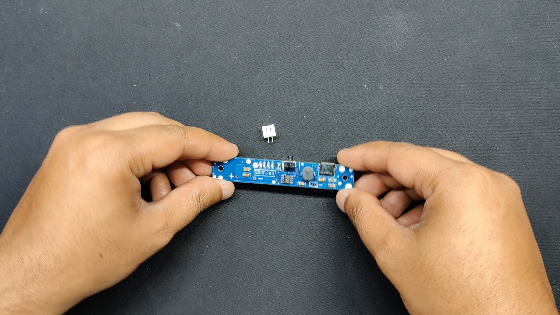
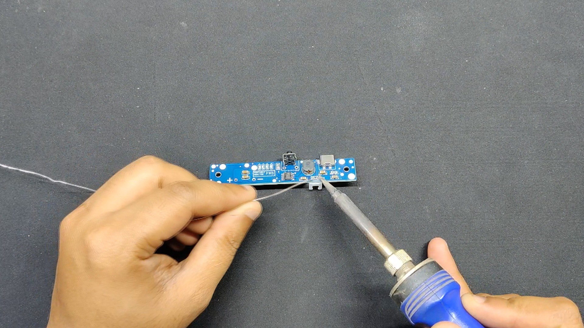
Following the completion of the schematic, we used the Cad model's layout and measurements to construct the circuit. We also followed the model's instructions for the placement of the Type C Port, the switch, and the two mounting holes.
Seeed Studio Fusion Service
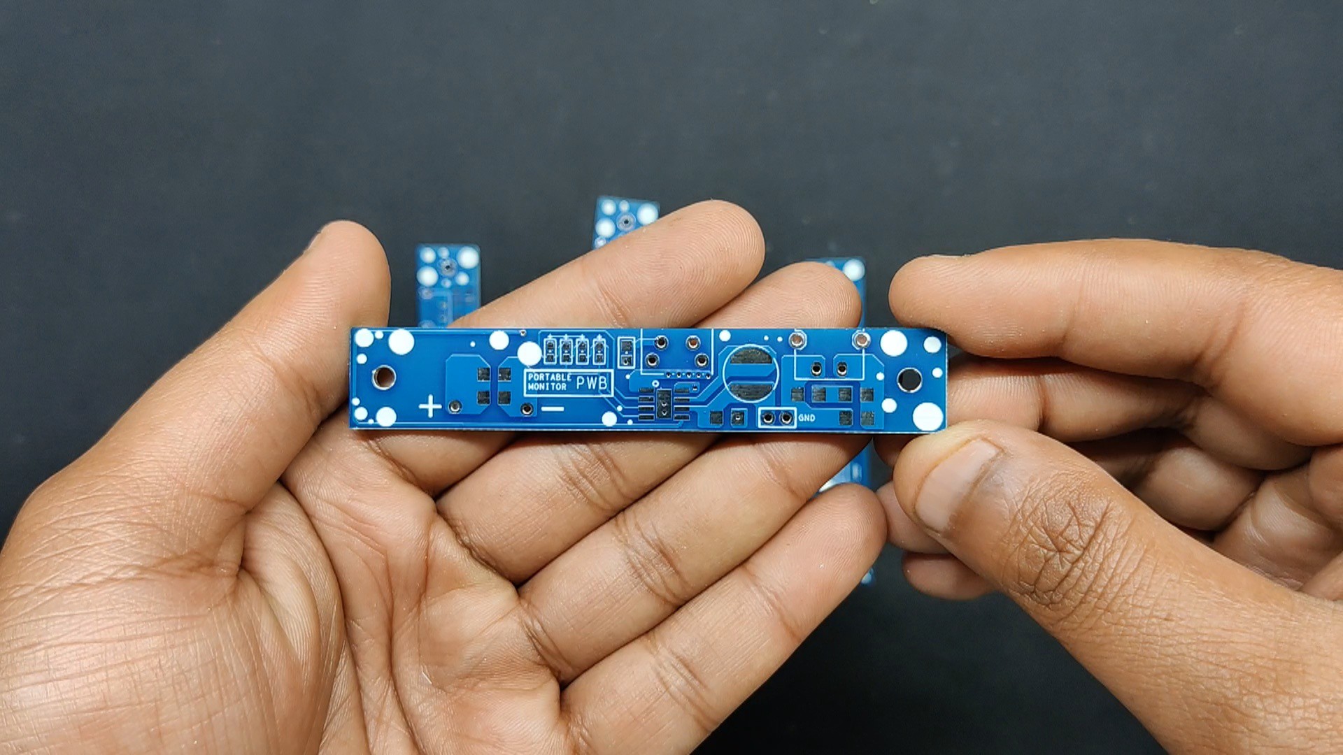
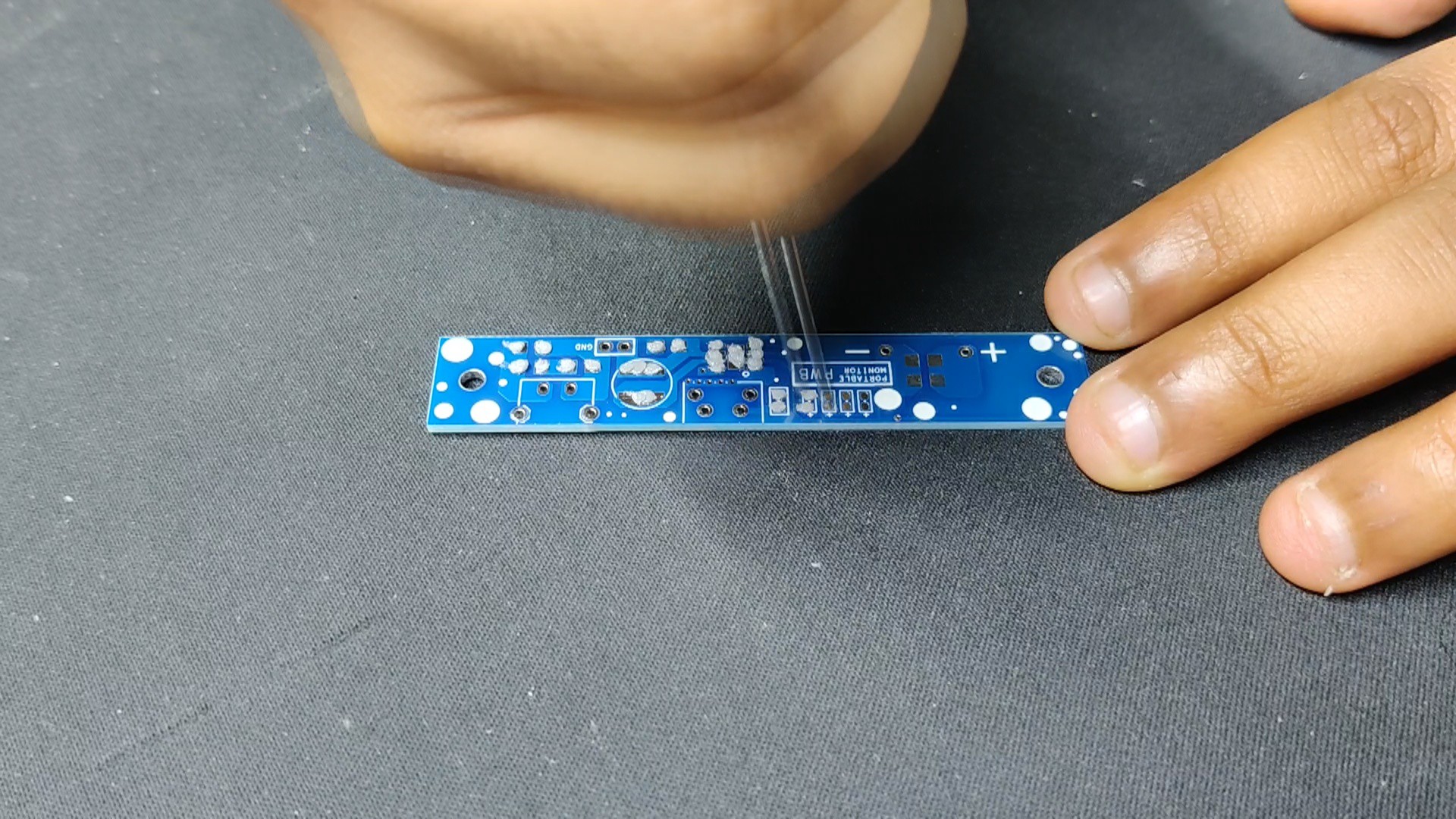
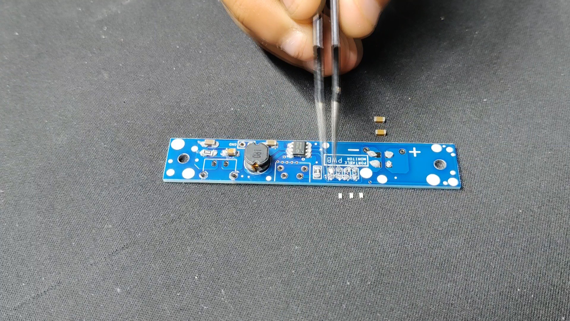
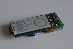
Following the completion of the Gerber data for the PCB, we uploaded the file to Seeed Fusion's website and ordered PCBs in a blue solder mask.
PCBs were received in a week, and their quality was super good considering the rate, which was also pretty low.
Seeed Fusion PCB Service offers one-stop prototyping for PCB manufacture and PCB assembly, and as a result, they produce superior-quality PCBs and fast turnkey PCBAs within 7 working days.
Seeed Studio Fusion PCB Assembly Service takes care of the entire fabrication process, from Seeed Studio Fusion Agile manufacturing and hardware customization to parts sourcing, assembly, and testing services, so you can be sure that they are getting a quality product.
After gauging market interest and verifying a working prototype, Seeed Propagate Service can help you bring the product to market with professional guidance and a strong network of connections.

 Jara
Jara
 will.sweatman
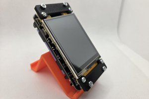
 filip-w