Arnov Sharma
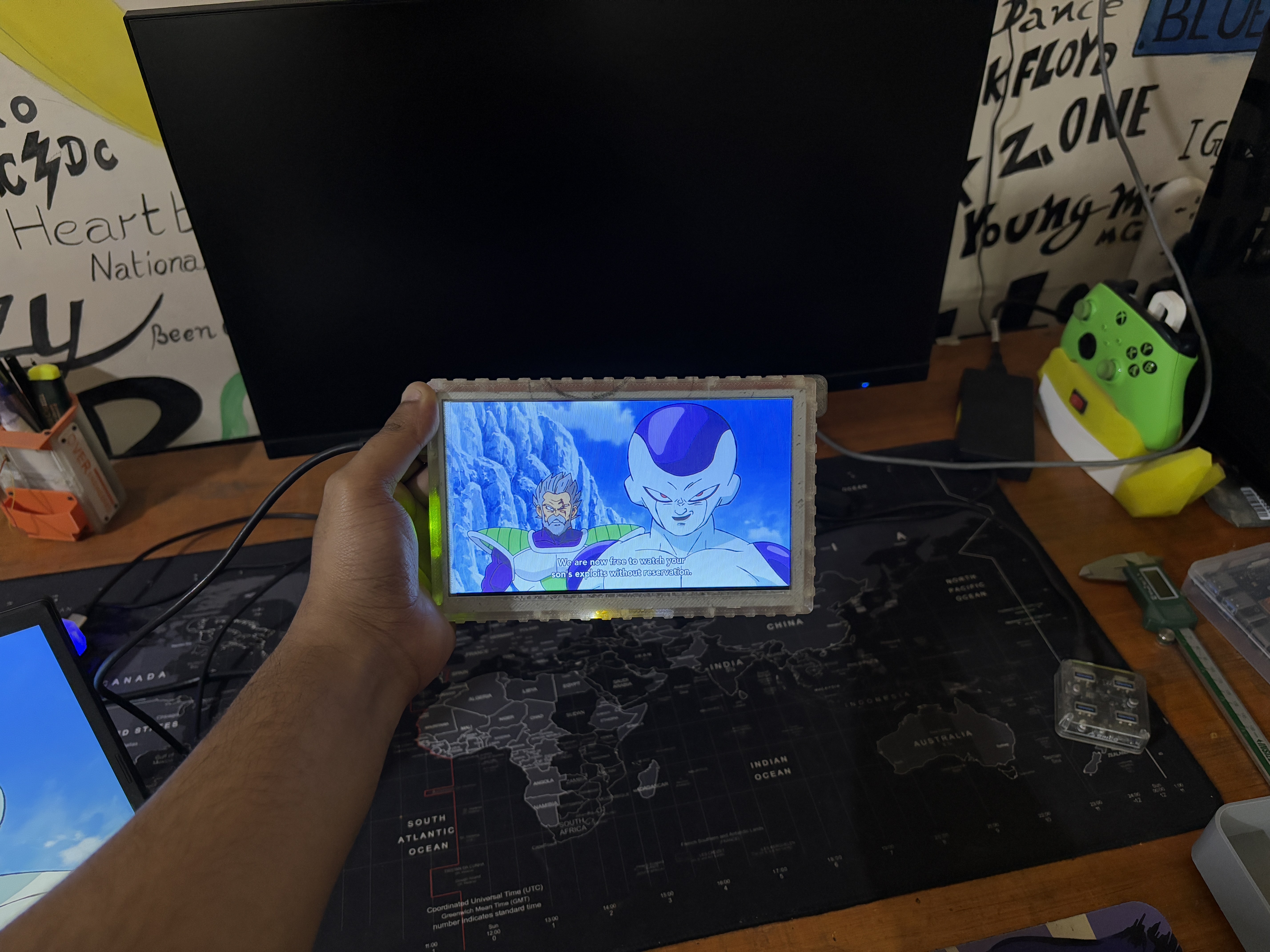

https://www.hackster.io/Arnov_Sharma_makes/diy-portable-monitor-b6bd24
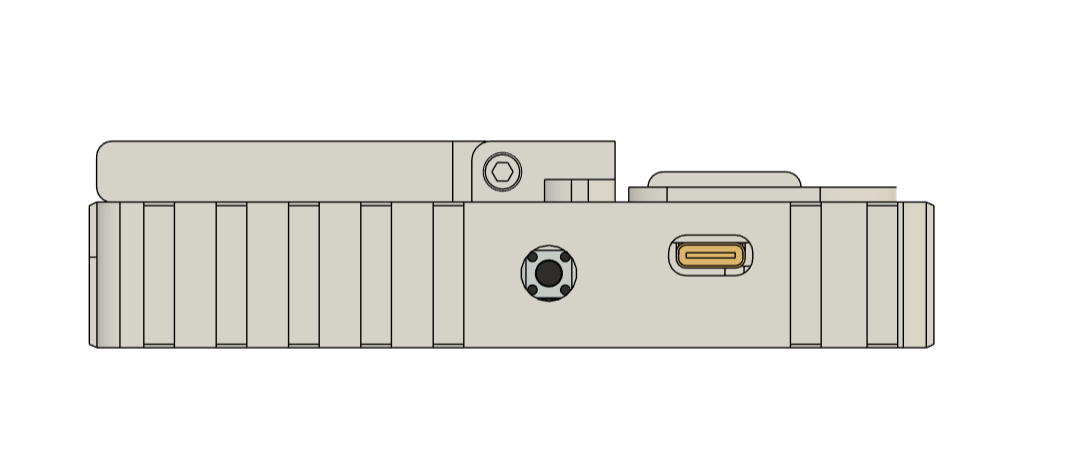
The Version 2 has a thinner LCD panel, resulting in a slimmer overall design of 19mm, making our design far slimmer than the previous version, which was more than 30mm.
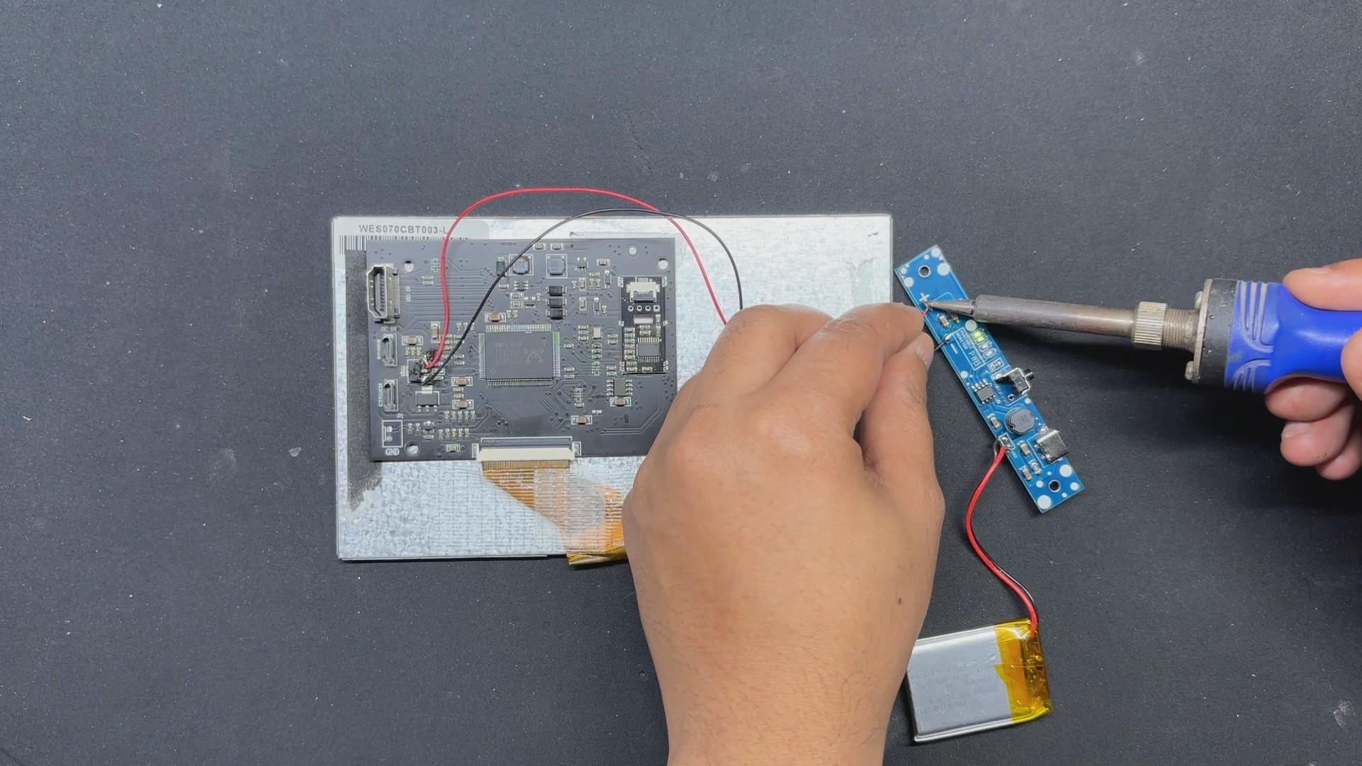
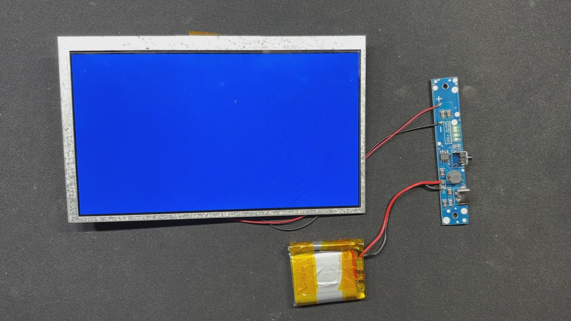
Here, we first arrange a thinner LCD panel that is only 6 mm thick and is connected to an HDMI board via an FPC cable. Because the display was thinner, we were able to reduce the size of our design even after including a battery pack and charging circuit inside the device.
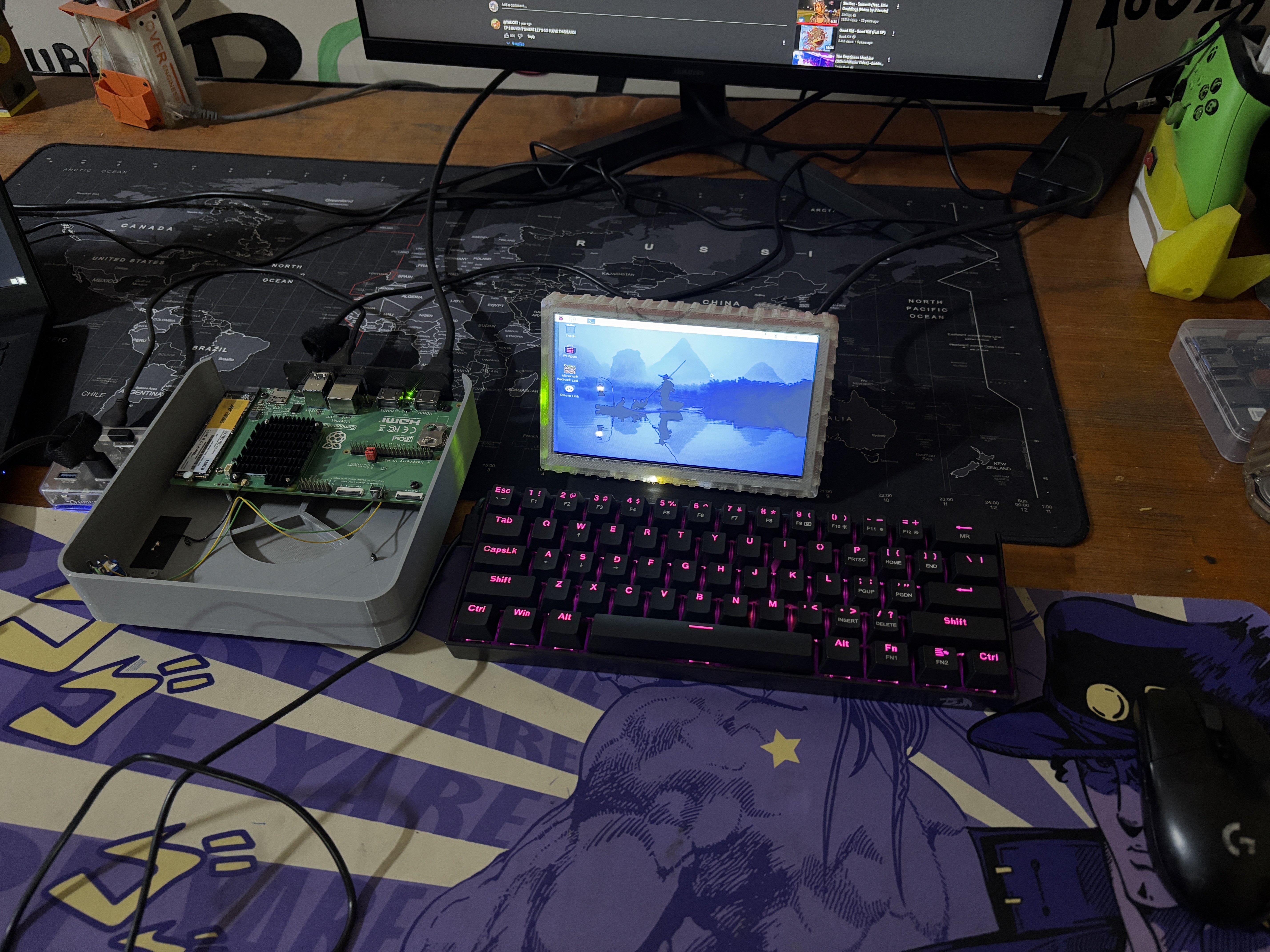
Because of its size, we may take this display in our bags and use it as a second monitor with our laptop or with a single-board computer setup, such as a Raspberry Pi.
3D Design
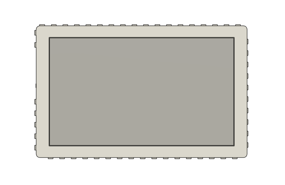
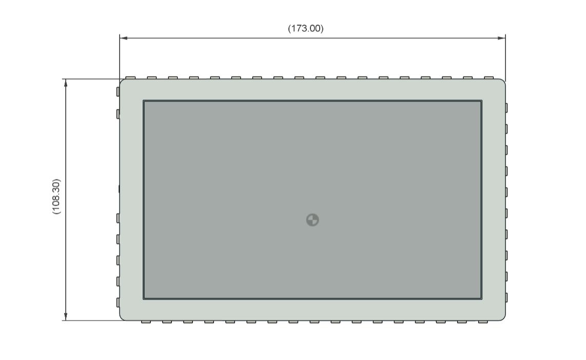
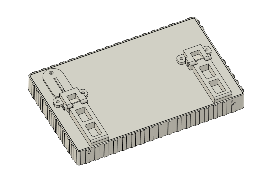
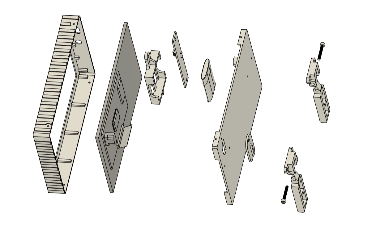
For the design of this project, we began by creating the model for our edited slim display panel. Based on the size of the display, we created the enclosure, which is divided into two parts: the front body, which holds the screen in place, and the lid part, which serves as a lid for our enclosure and holds the circuit and battery from the inside, as well as a custom tilt stand from the exterior.
The lid part is attached to the front part with four M2 screws, which are positioned on the top and bottom of the front section, respectively.
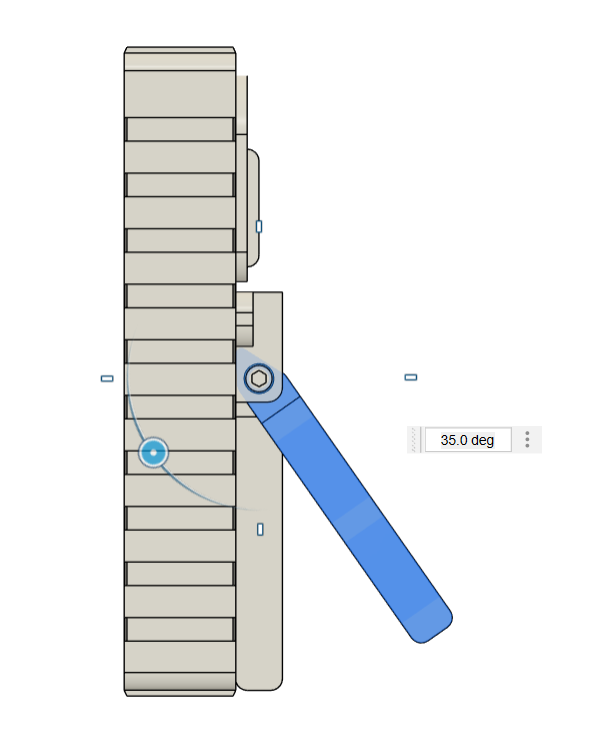
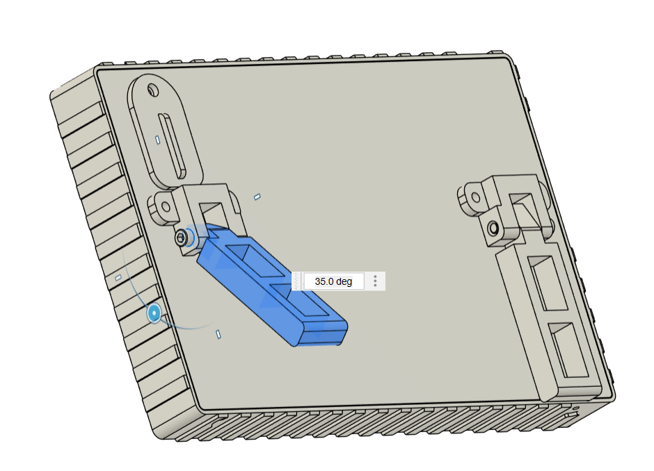
On the back side, we also designed a tilt stand that is made up of two parts: the holder and the tilt stand, which is mounted to the holder with an M2.5 nut and bolt. We've introduced a maximum tilt angle of 35 degrees, and the tilt stand cannot exceed it. We installed two tilt stands to keep the display stand steady.
The front section, tilt stand, holder, and battery holder are all printed with transparent PLA using a 0.6mm nozzle. The lid is printed in orange PLA.
Circuit

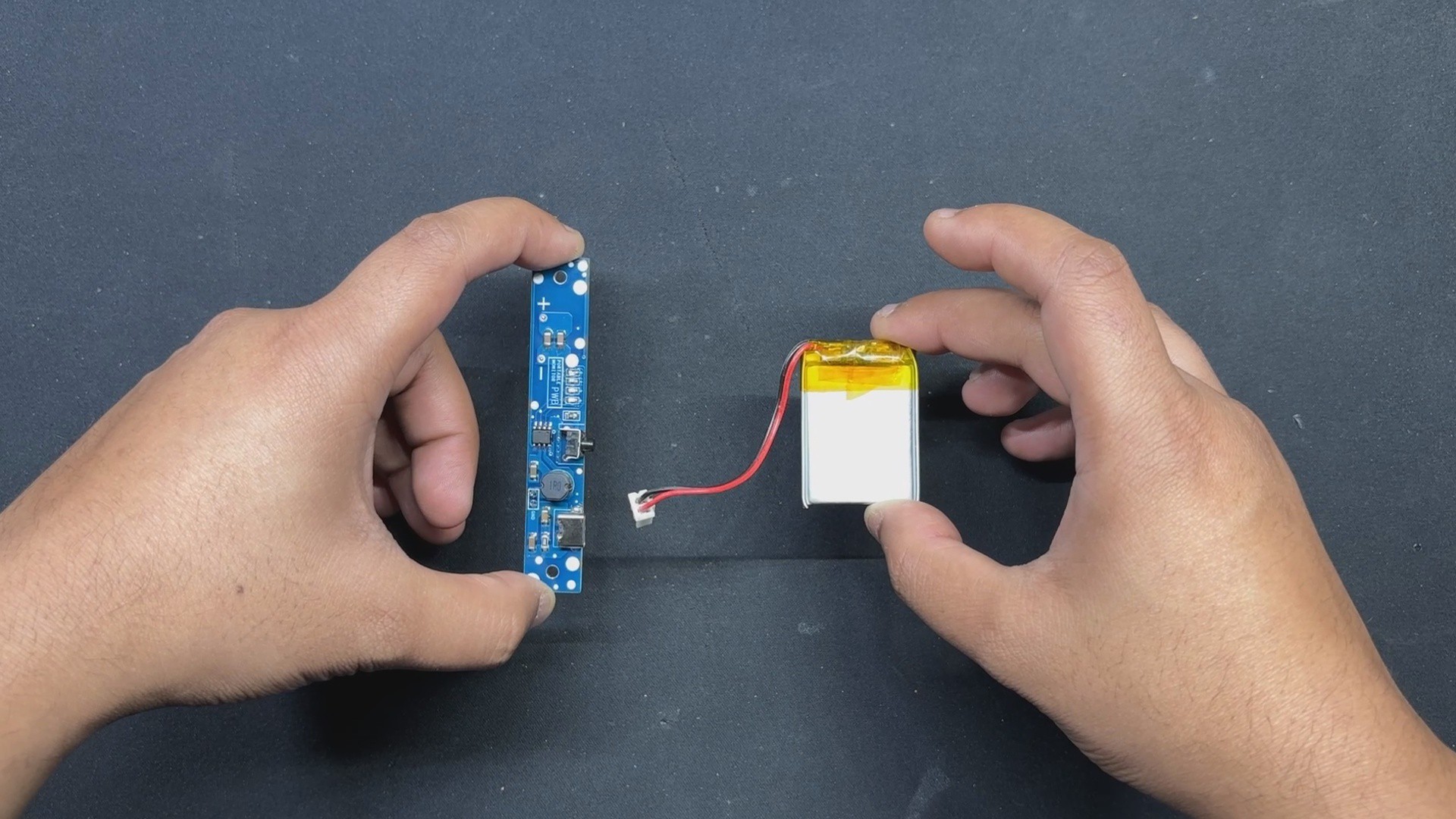
Here, we are reusing the circuit used in version 1 of this project.
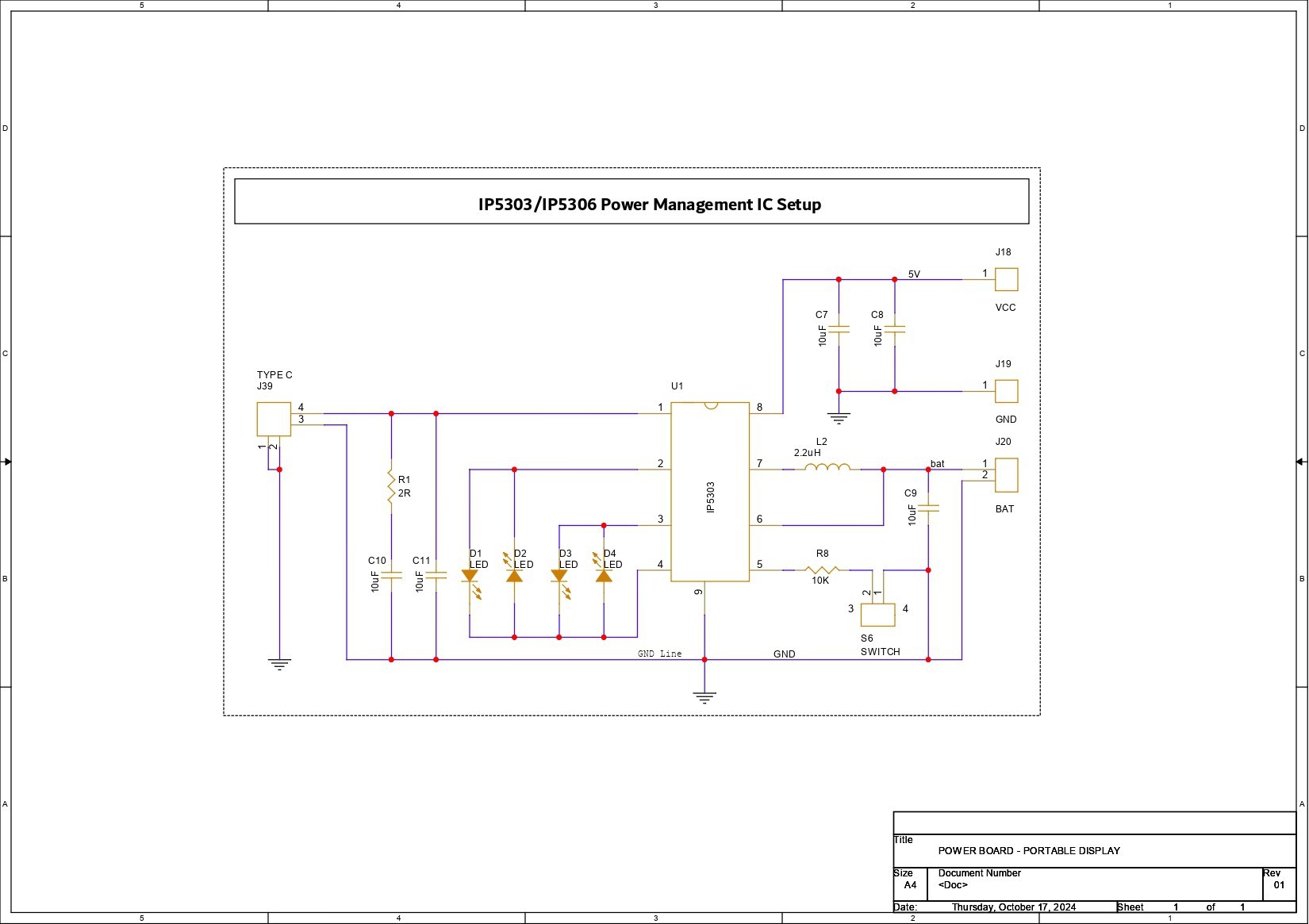
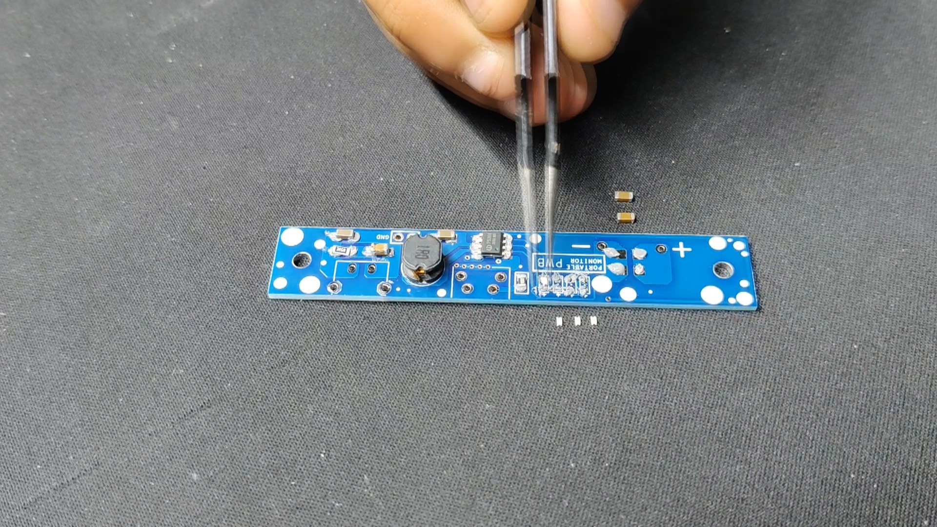
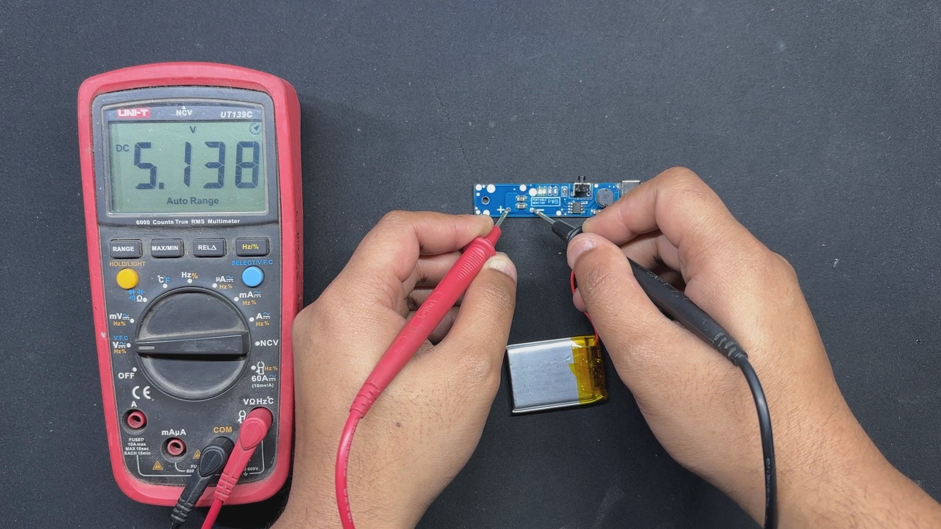
We're utilizing the IP5306 Power Management IC, which draws a consistent 5V/2A from a 3.7V Li-ion battery. Its high-cut and low-cut characteristics prevent overcharging and overdischarging of the cell.
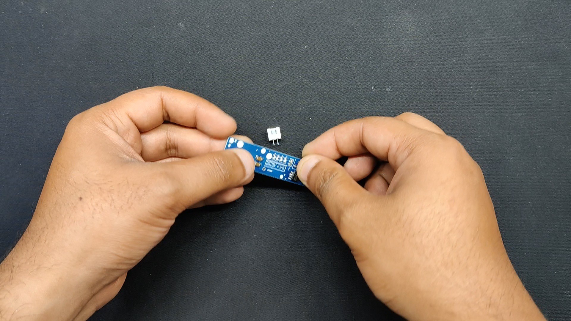
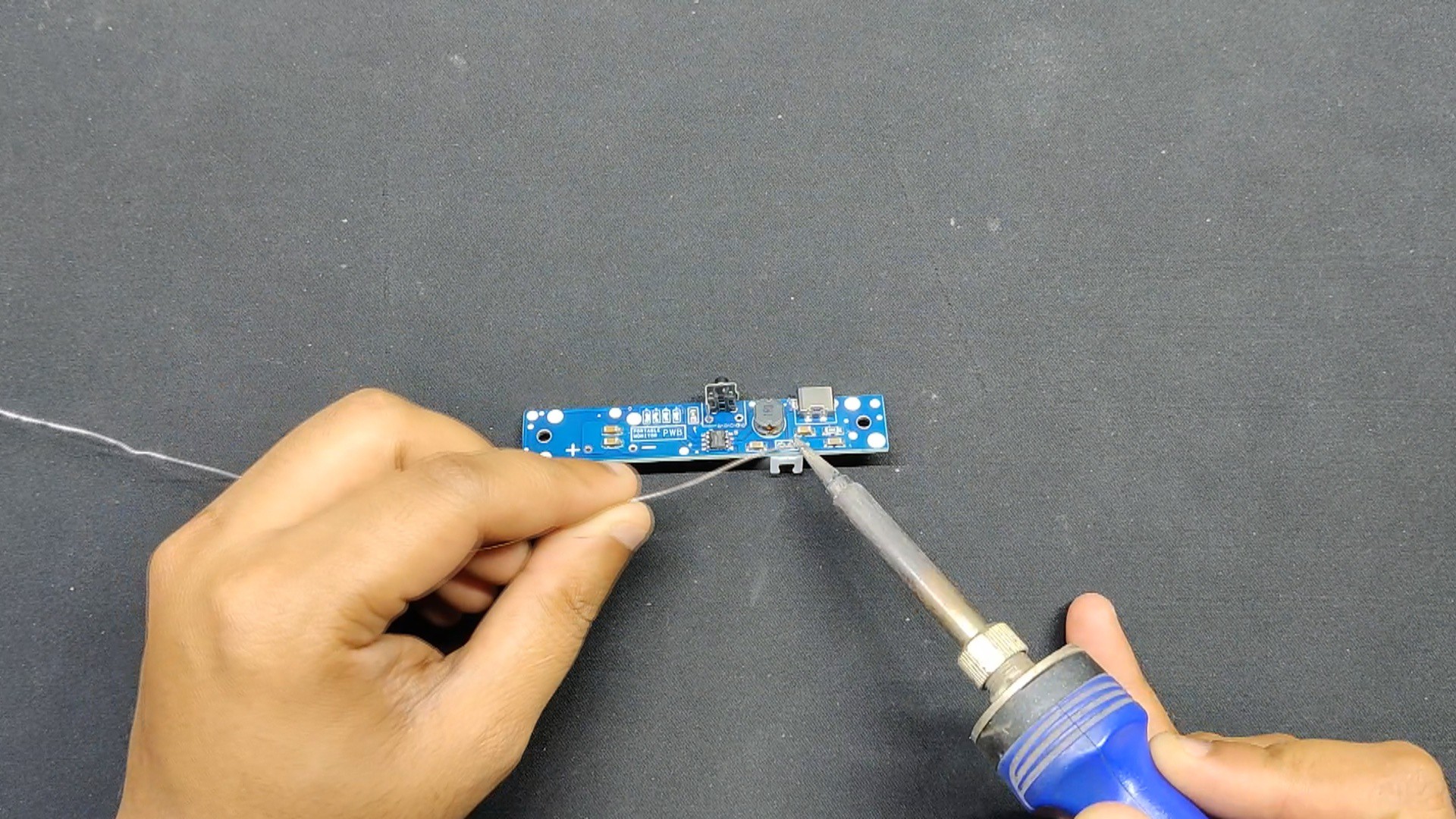
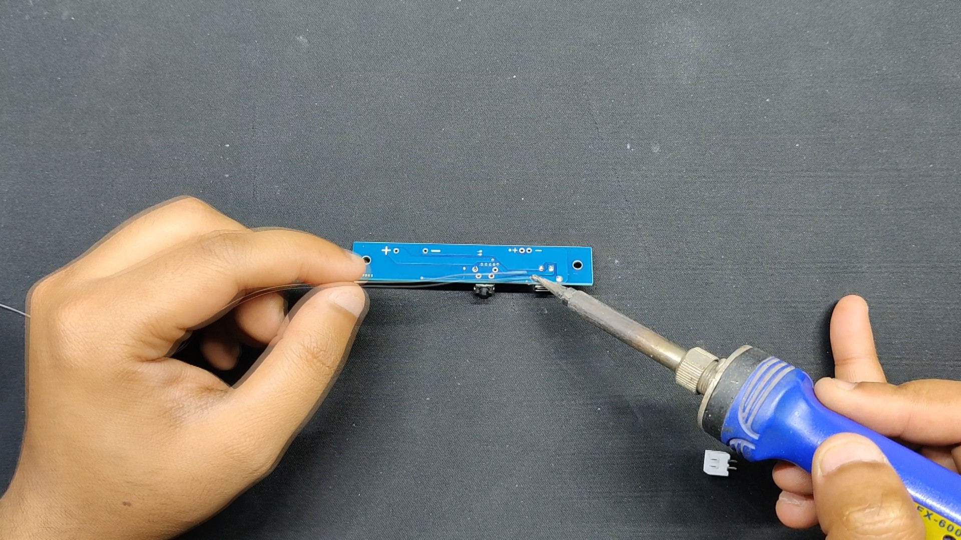
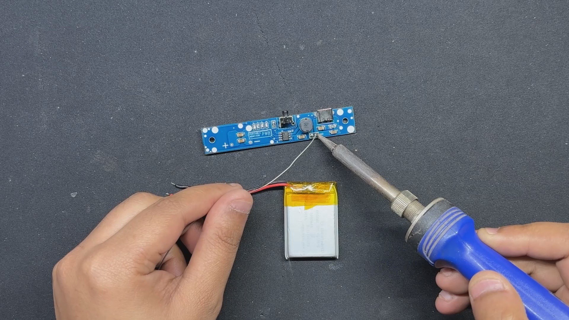
The charging port we're using is a Type C through-hole port that connects to the IC charging port. Along with the charging port and GND, we included a 10uF filter capacitor and a 10uF capacitor combination with a 2Ohm resistor.
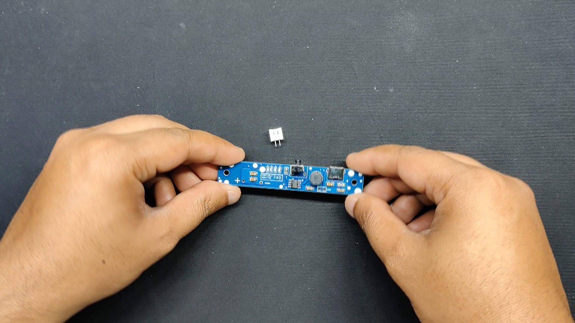
Additionally, four LEDs—which will serve as battery-full indication LEDs—are added to the IC's LED port.
To turn this device on and off, a push button has been added.
Additionally, we added two extra filter capacitors to the IC and GND outputs.
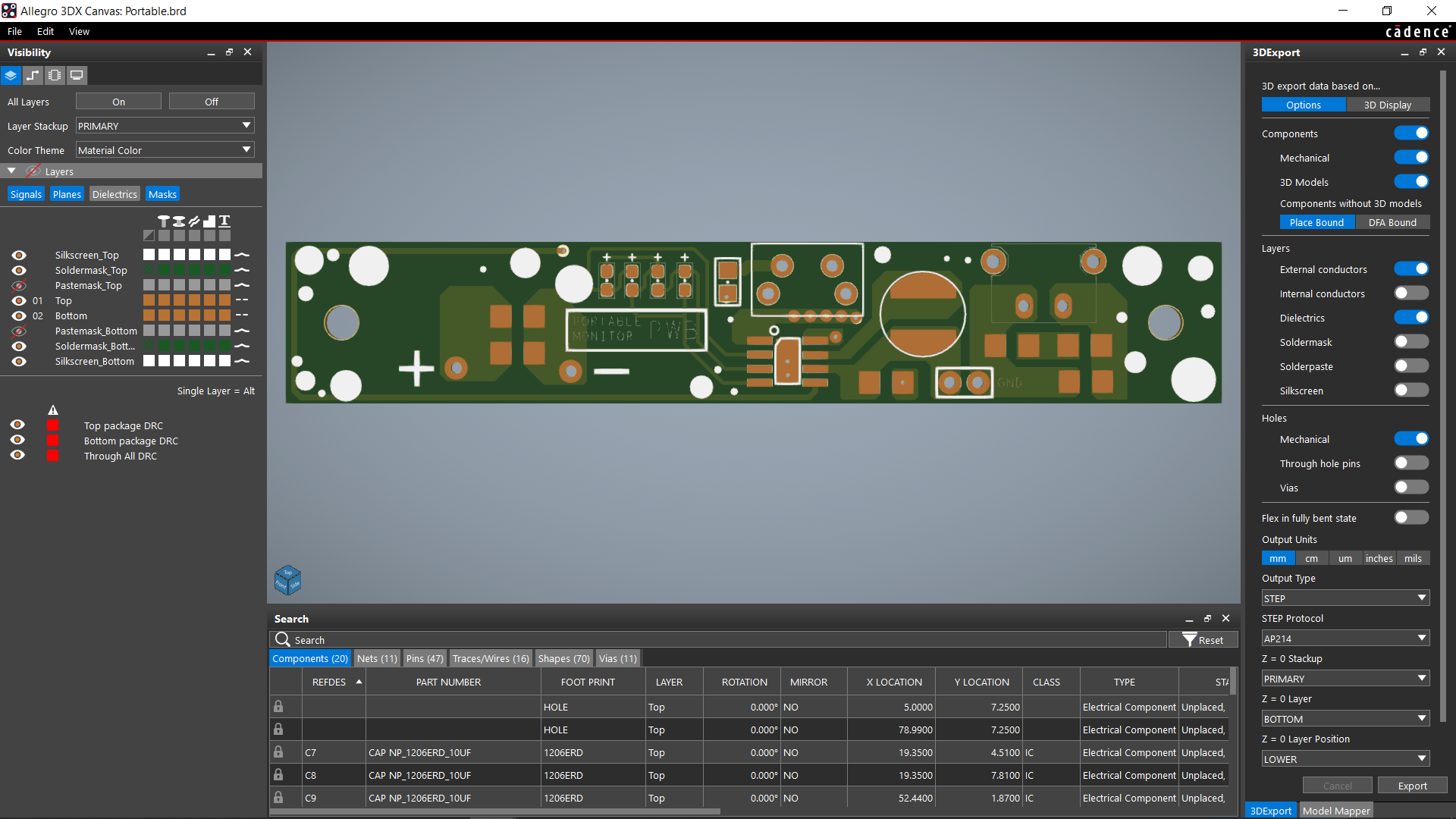
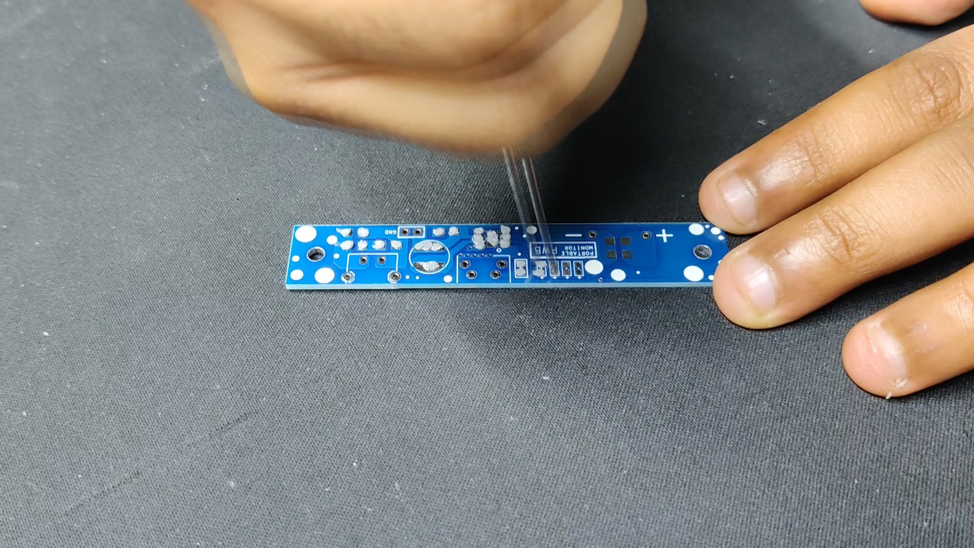
Following the completion of the schematic, we used the Cad model's layout and measurements to construct the circuit. We also followed the model's instructions for the placement of the Type C port, the switch, and the two mounting holes.
Seeed Studio Fusion
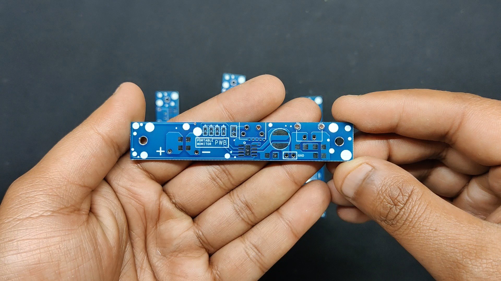
Following the completion of the Gerber data for the PCB, we uploaded the file to Seeed Fusion's website and ordered PCBs in a blue solder mask.
PCBs were received in a week, and their quality was super good considering the rate, which was also pretty low.
Seeed Fusion PCB Service offers one-stop prototyping for PCB manufacture and PCB assembly, and as a result, they produce superior-quality PCBs and fast turnkey PCBAs within 7 working days.
Seeed Studio Fusion PCB Assembly Service takes care of the entire fabrication process, from Seeed Studio Fusion Agile manufacturing and hardware customization to parts sourcing, assembly, and testing services, so you can be sure that they are getting a quality product.
After gauging market interest and verifying a working prototype, Seeed Propagate Service can help you bring the product to market with professional guidance and a strong network of connections.
Thinner Display
The display utilized in this build is the same 7-inch LCD display that was used in the first project. But, if that is the case, why does the display that we are using appear to be quite thinner? This is because we removed all of the unnecessary things attached to the actual LCD...
Read more »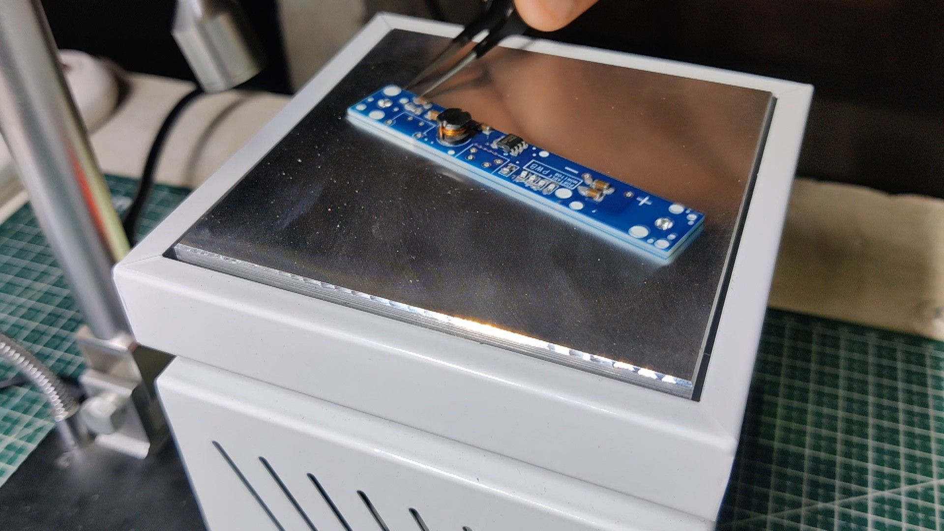
 Tony E. Nazzal