 Arnov Sharma
-
1PCB Assembly process
![]()
![]()
![]()
![]()
![]()
![]()
![]()
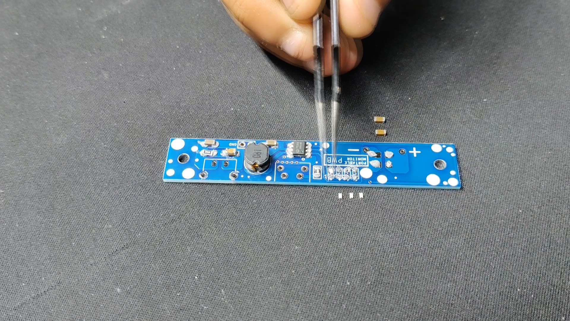
- Utilizing a solder paste dispensing syringe, we apply solder paste to each component pad to begin the Main Circuit Assembly process. Here, we are utilizing Sn/Pb 63/37 solder paste, which has a melting temperature of 190 °C.
- Next, we pick each SMD component and place them in their correct locations.
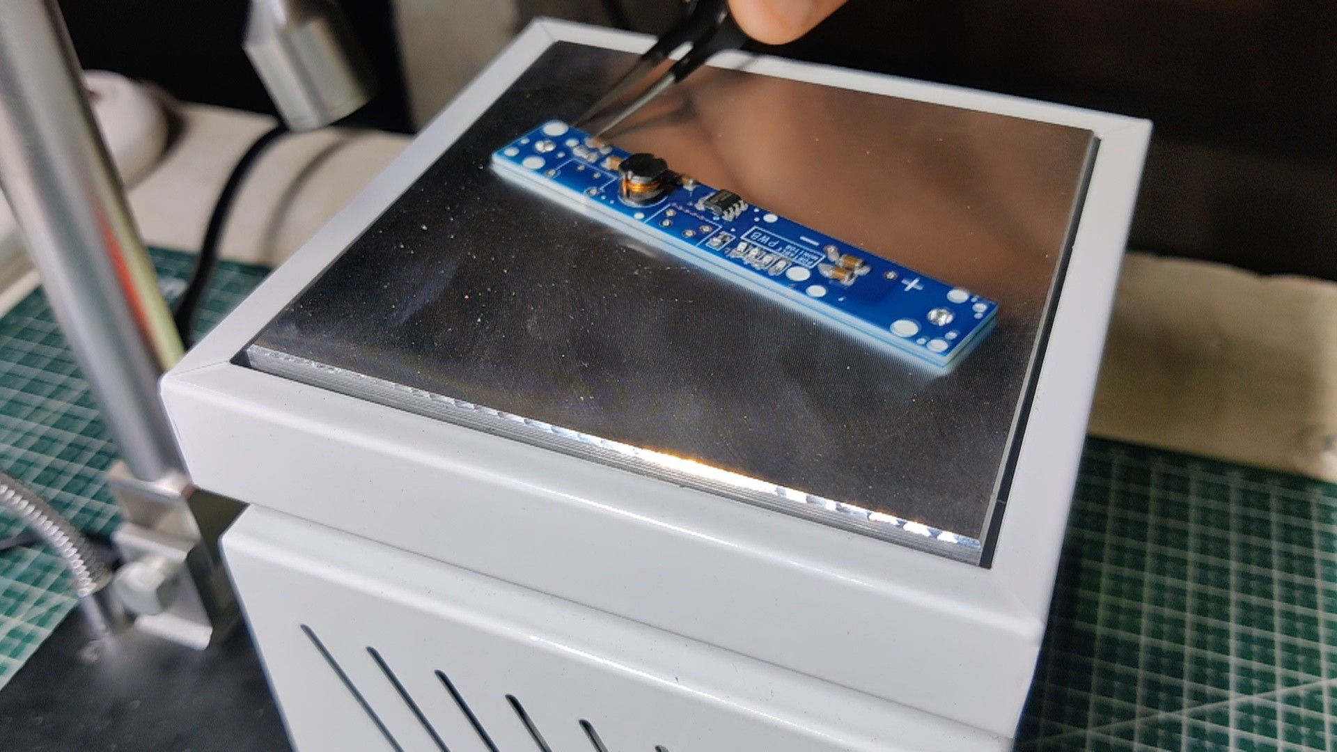
- All of the components are then permanently bound to their pads when the entire circuit is set on the reflow hotplate, which heats the PCB to the solder paste melting temperature.
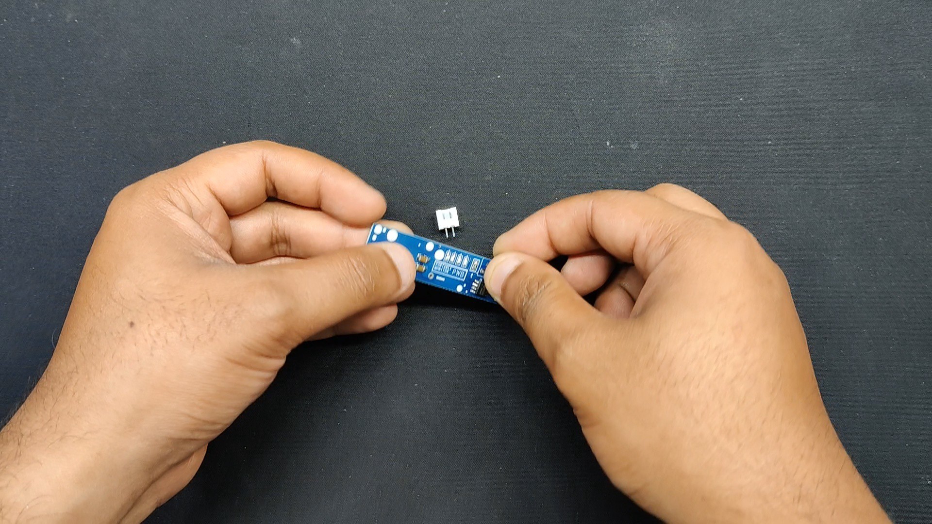
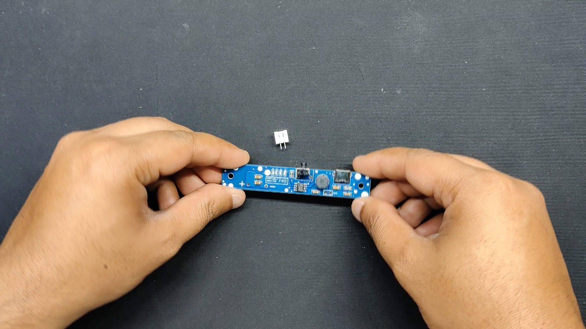
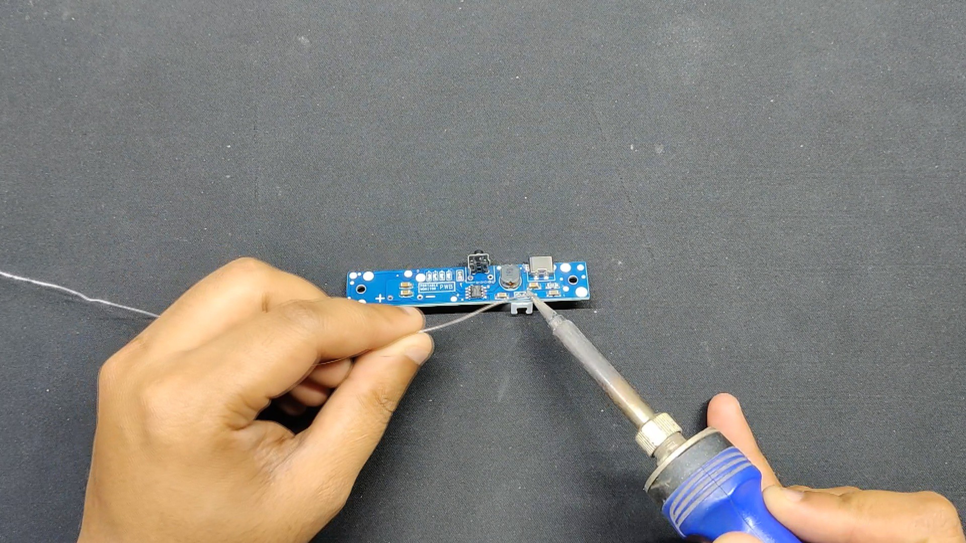
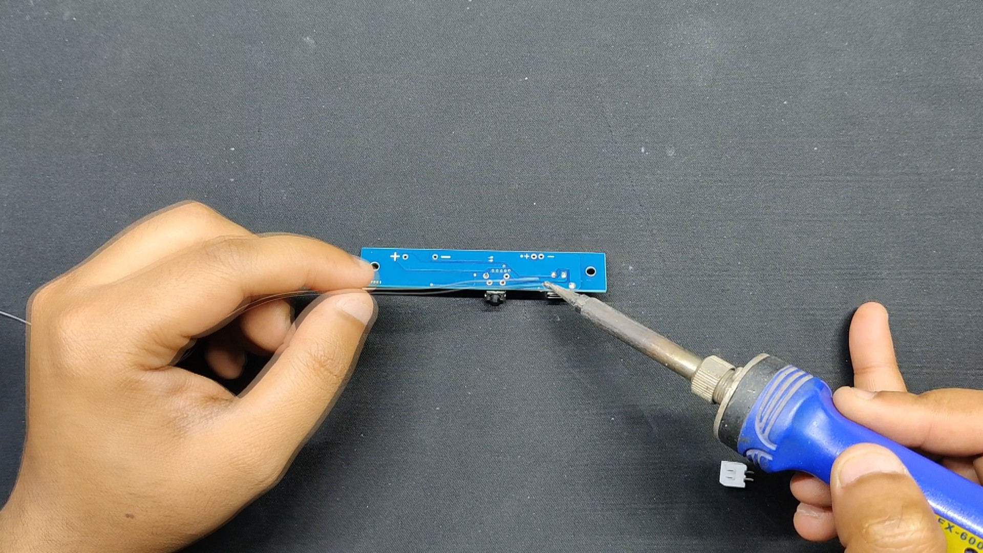
- Next, we positioned every THT component—including the Type C port, the vertical push button, and the CON2 JST connector—in its proper location.
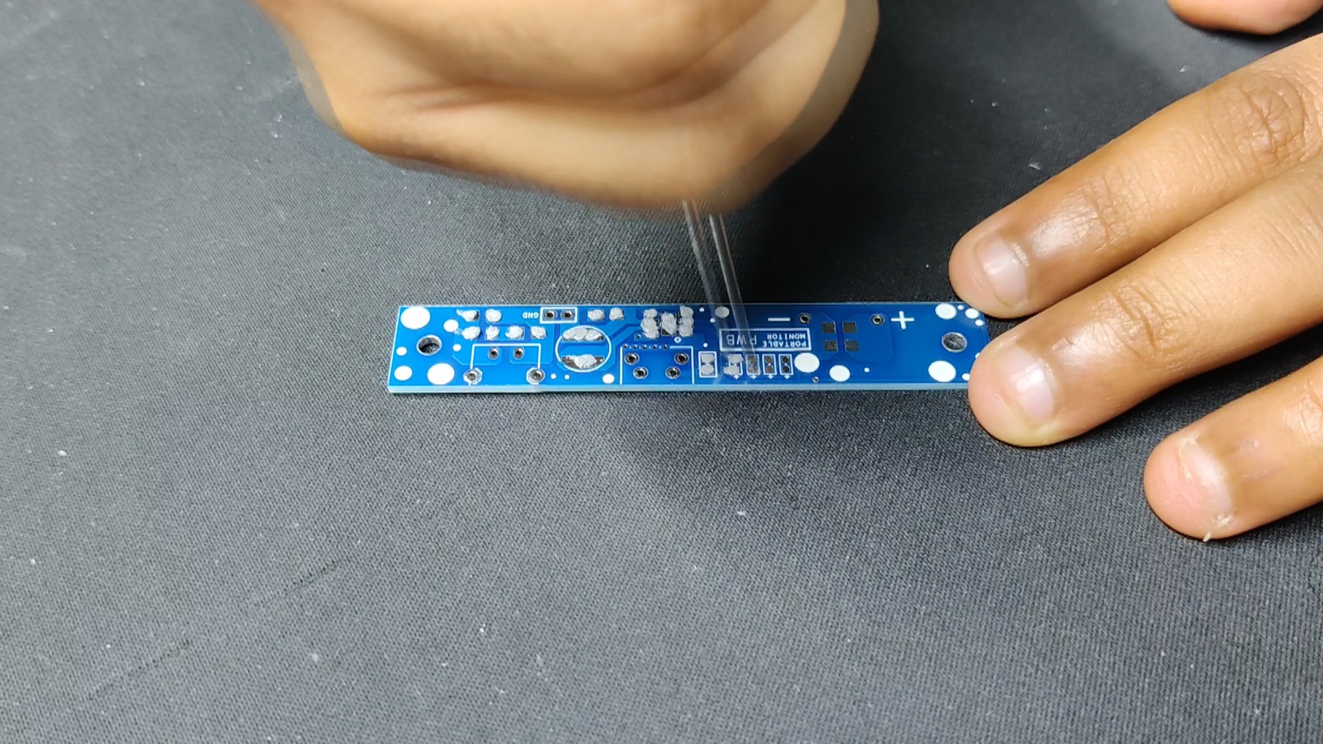
- The soldering iron is then used to solder the pads of each THT component from the board's bottom side.
-
2Power Source
![]()
![]()
![]()
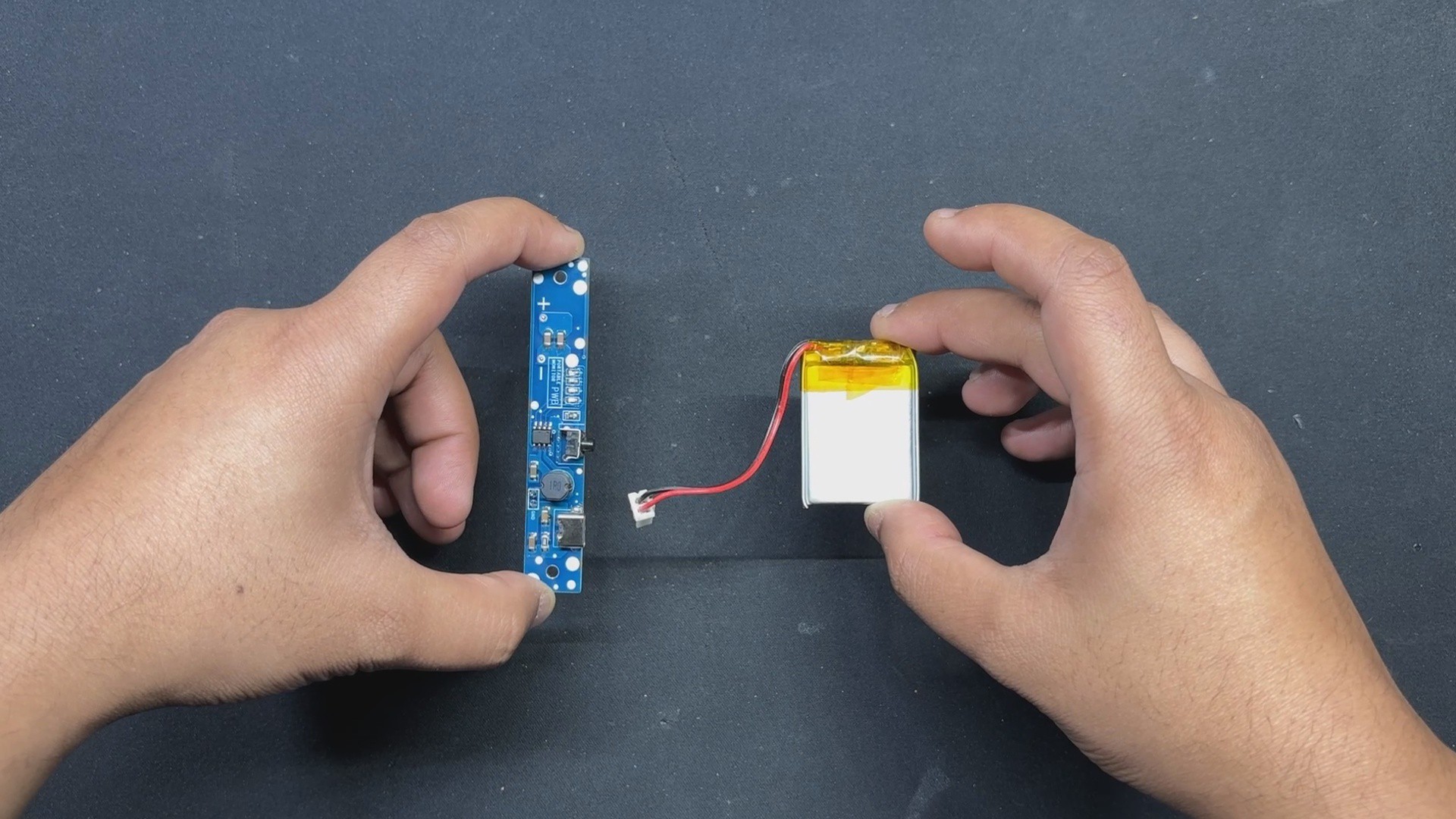
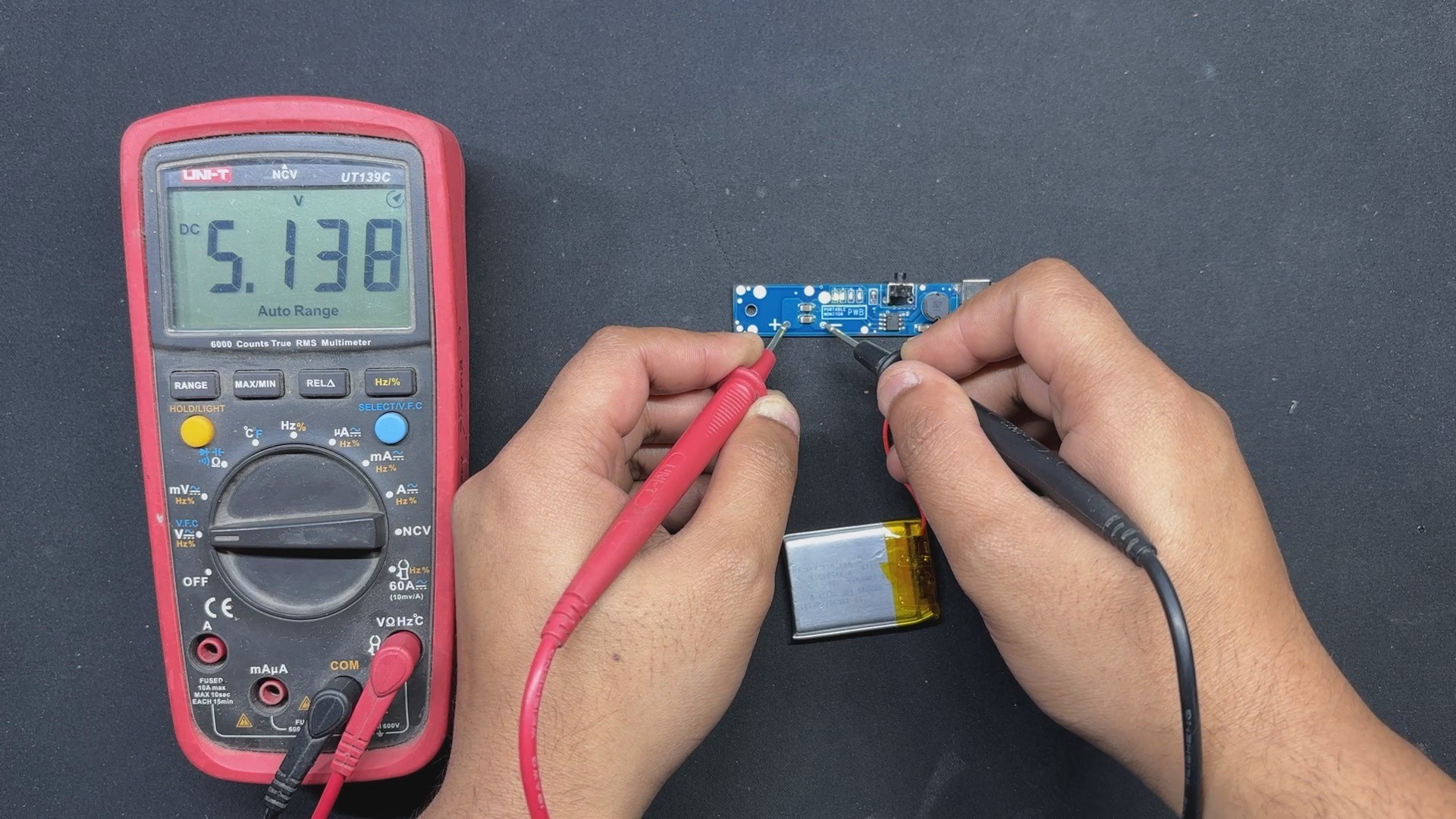
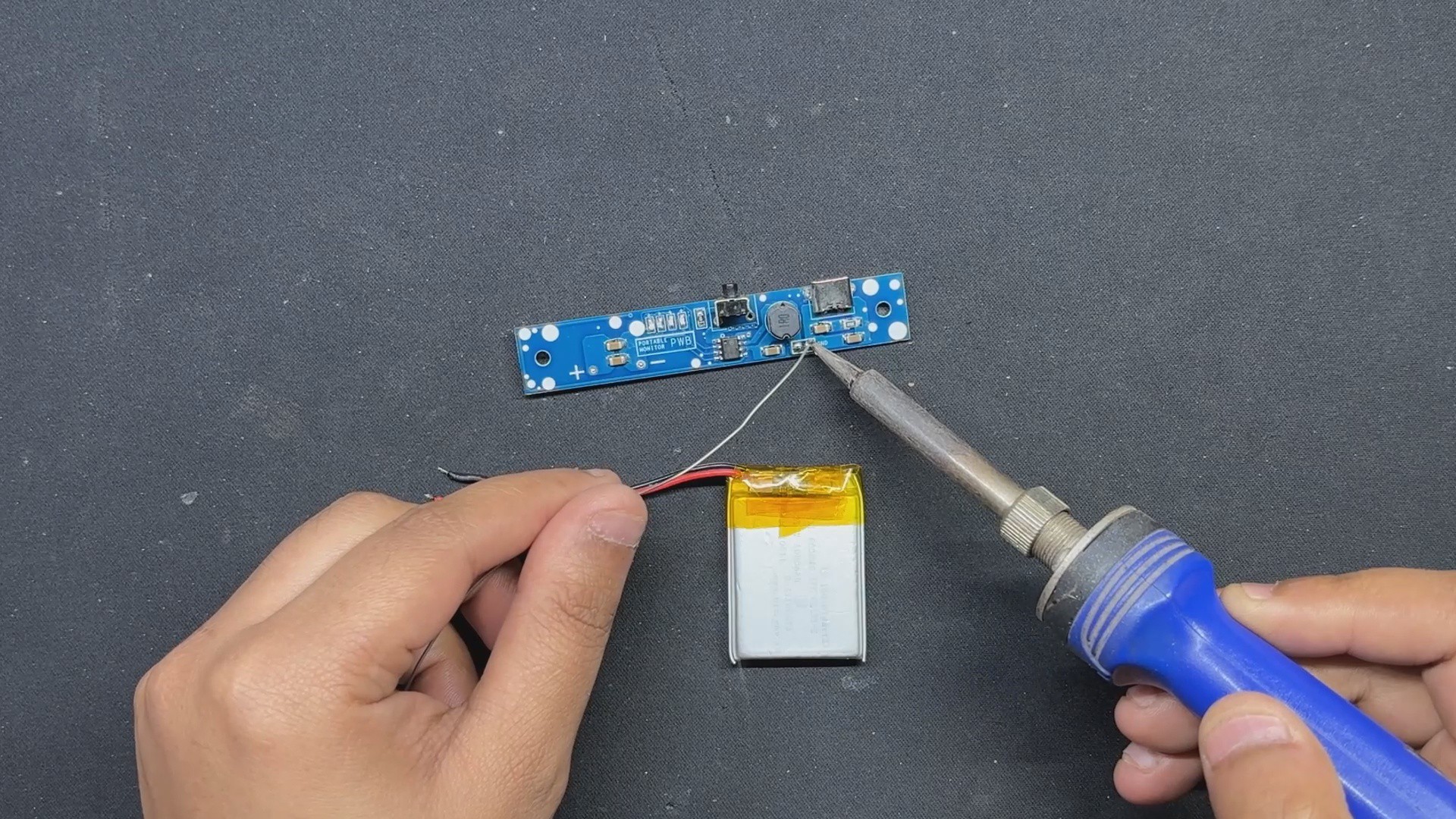
The power supply for this project is a 1000mAh Li-PO cell, which will power our display. Using a soldering iron, we solder the circuit's positive and negative terminals to the battery connector.
By pressing the vertical push button, the circuit begins to function and provides a stable voltage of 5V at the circuit output.
-
3Display and Power Circuit Assembly
![]()
![]()
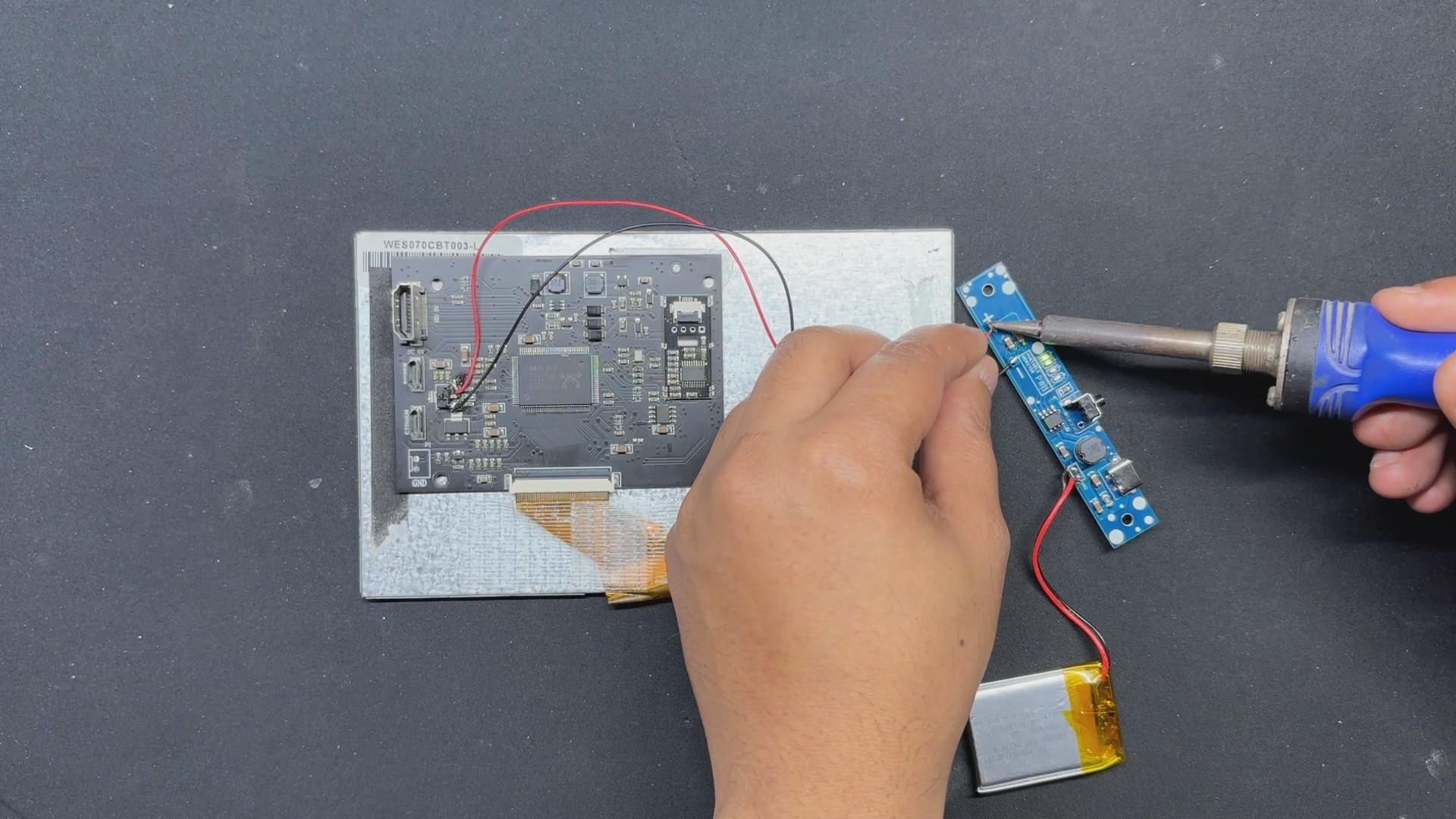
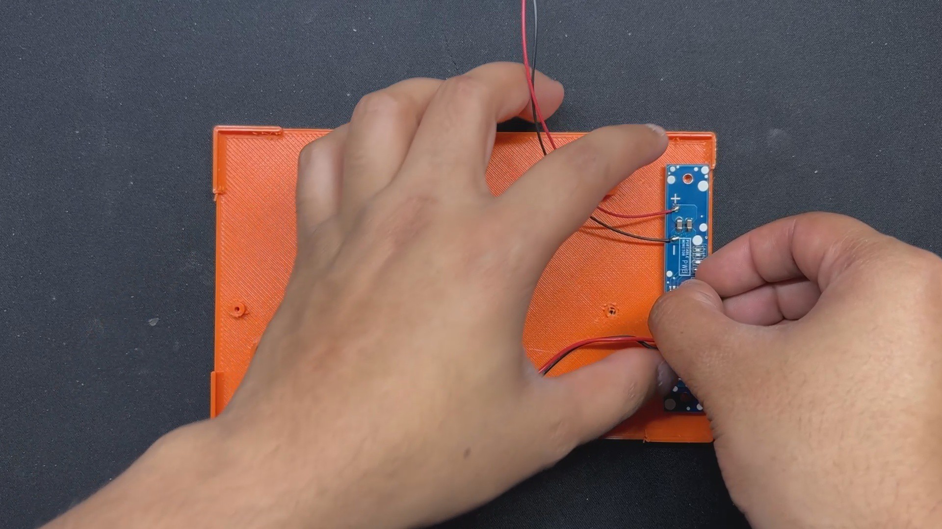
The display's driver circuit does not provide a 5V output for powering the panel. This was challenging, but we resolved it by connecting a USB cable to the Power Micro USB port, then using a multimeter in continuity checking mode to find out that the 5V pin is connected to the IN port of a voltage regulator.
- We soldered a connecting wire between the voltage regulator's IN port and the 5V power circuit. GND was linked to the voltage regulator's GND terminal.
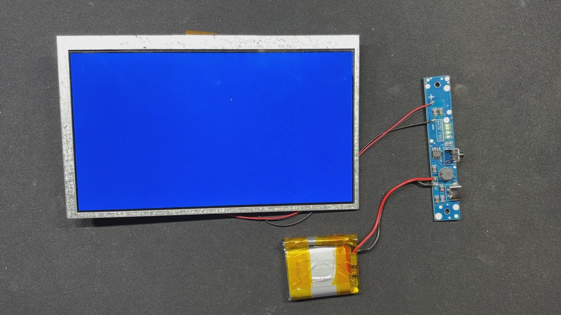
- When we switch on the circuit after soldering, the screen illuminates, indicating that our setup is operational.
-
4Frame Assembly Process
![]()
![]()
- We start the frame assembly process by placing the display in its proper location inside the frame enclosure.
- We use hot glue to secure the display. Hotglue will keep the display intact, so apply it to all four corners, including the midpoints between corners.
-
5LID and Power Circuit Assembly
![]()
![]()
![]()
- Lid assembly begins with the power circuit being placed over two screw bosses and then secured with two M2 screws.
- The battery is then secured within the lid using a battery holder. We utilize M2 screws to secure the battery holder and lid.
-
6FINAL ASSEMBLY
![]()
![]()
![]()
![]()
![]()
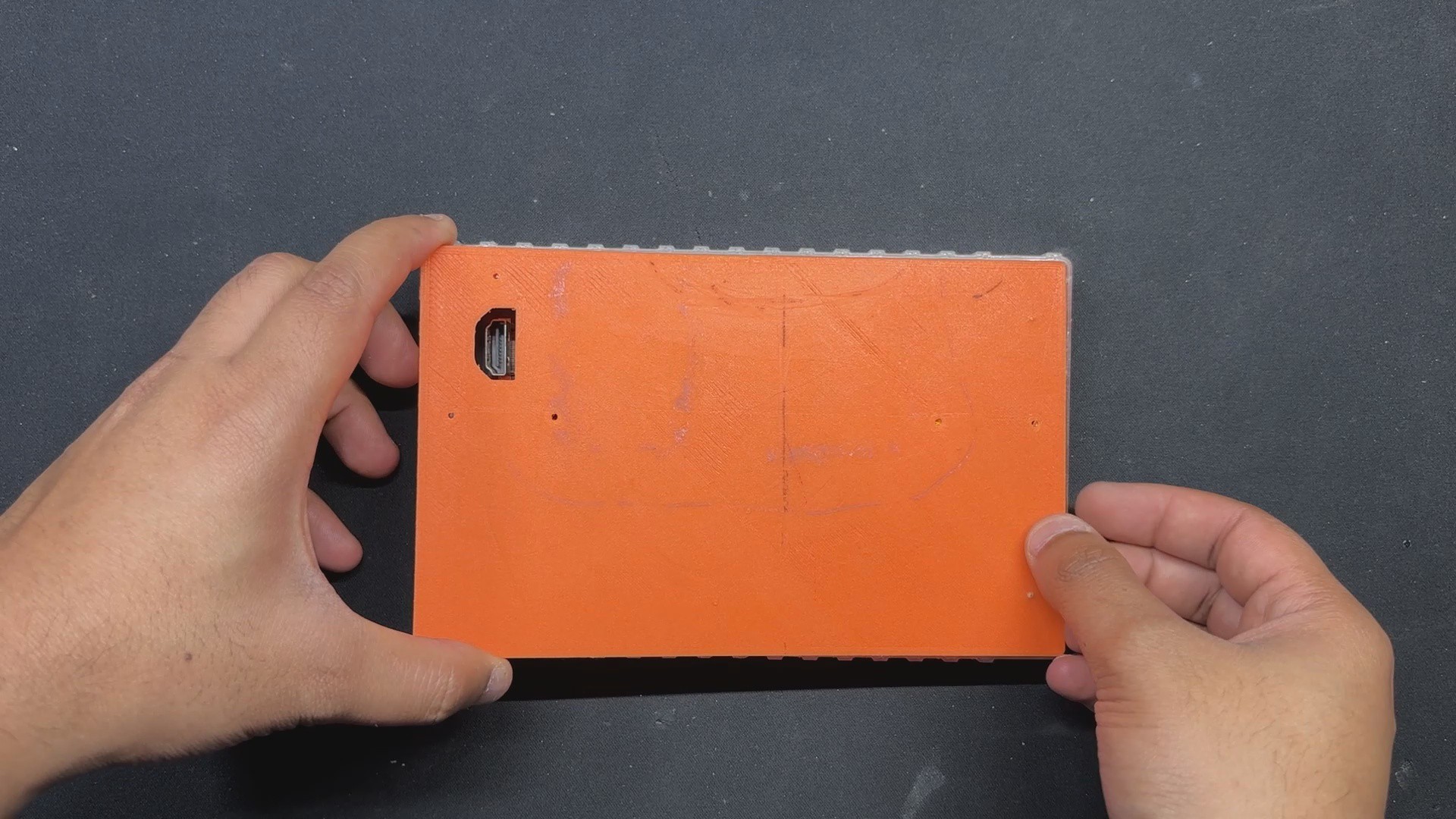
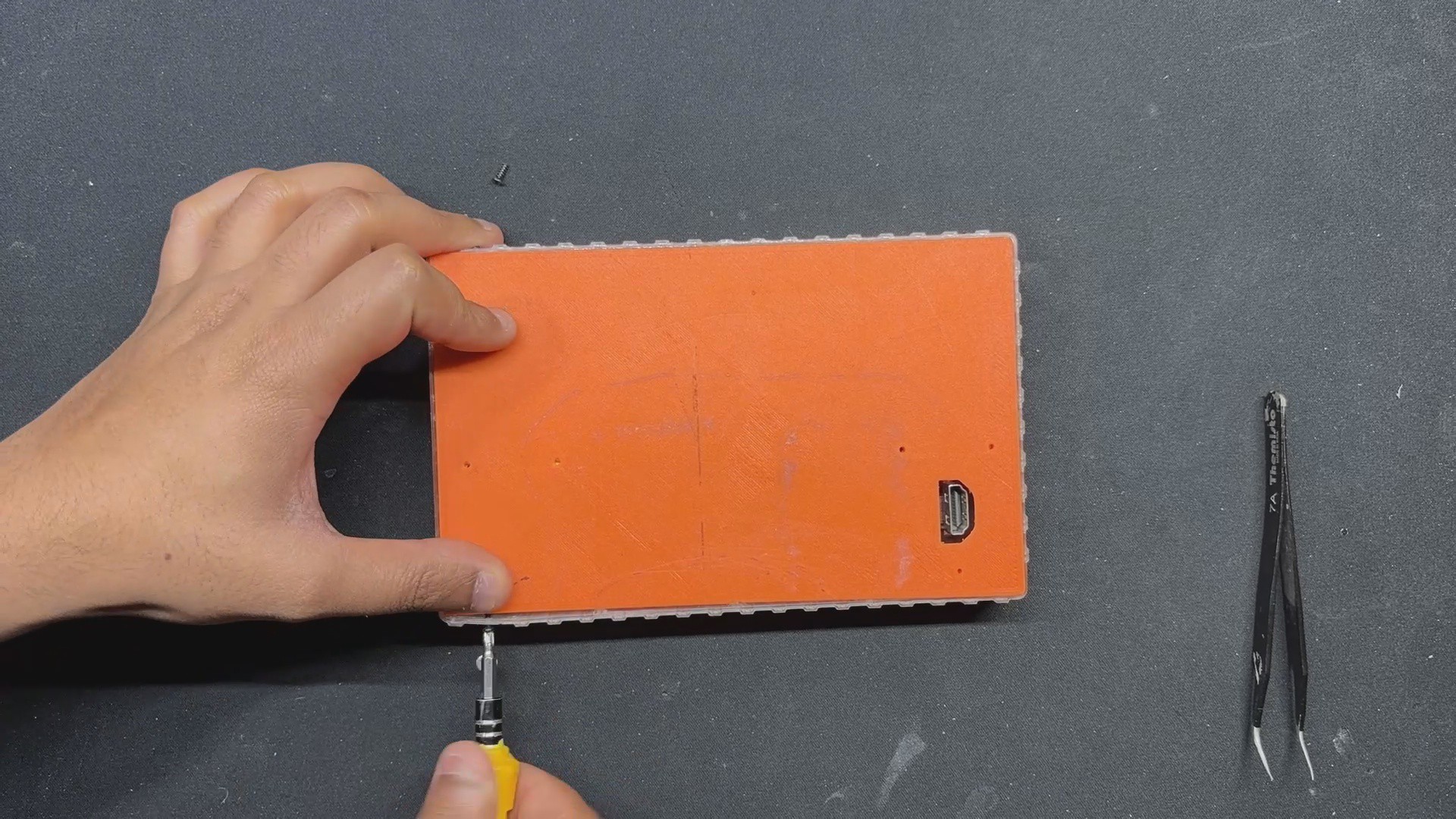
- Final assembly begins with sliding the lid part onto the back side of the front enclosure and then securing it with M2 screws from the top and bottom faces.
- Next, we install and lock the HDMI Cover over the opening on the lid part that was designed to give access to the HDMI ports.
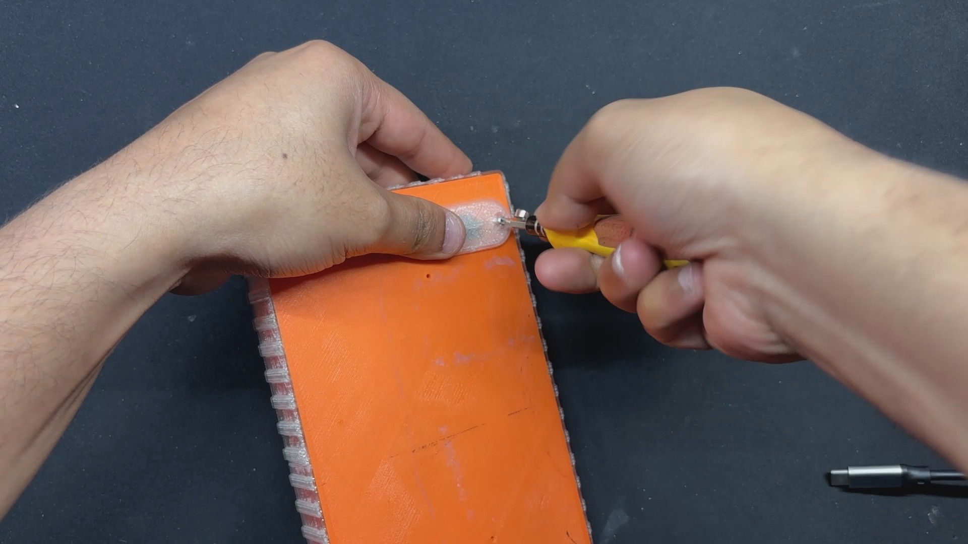
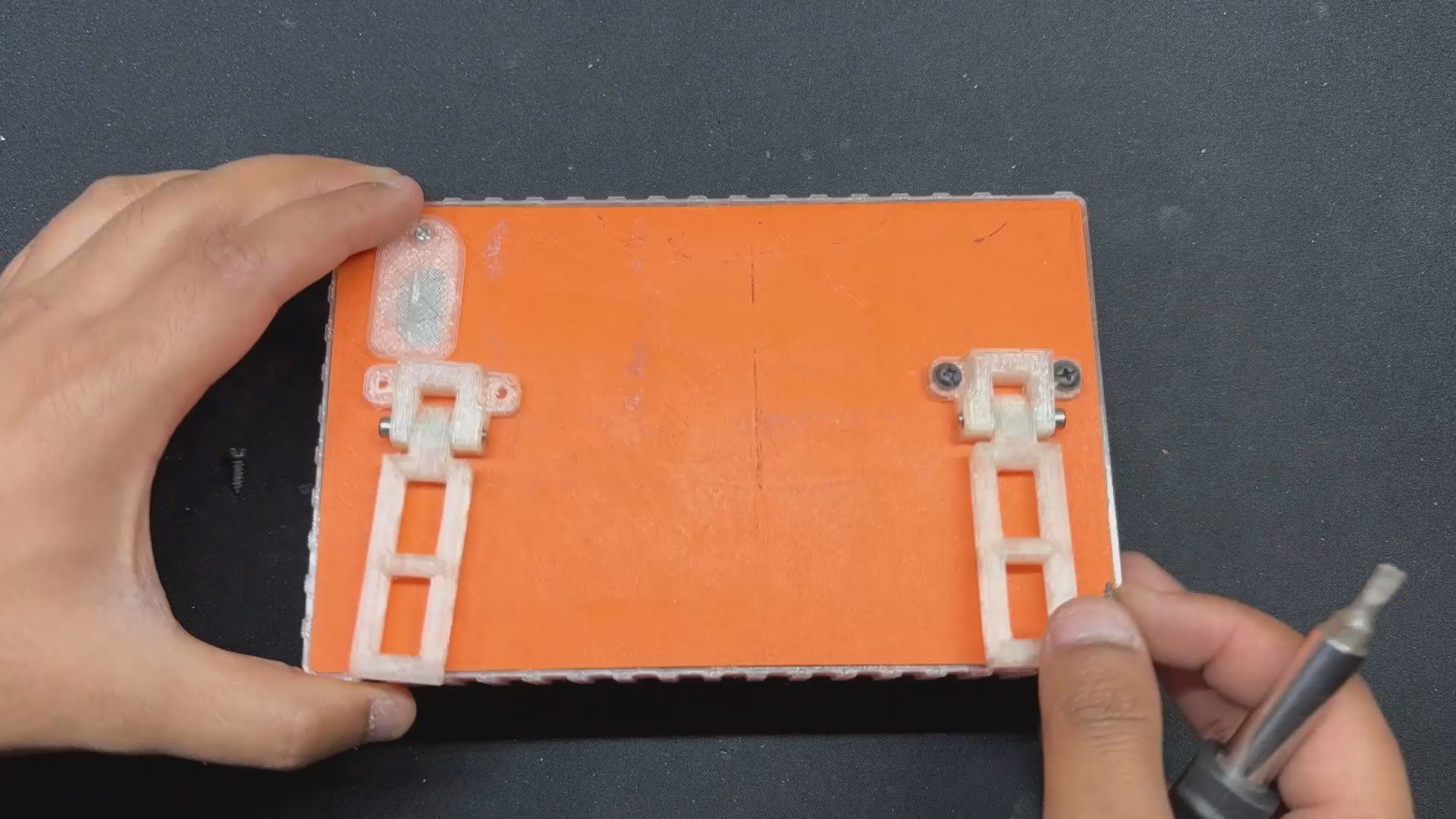
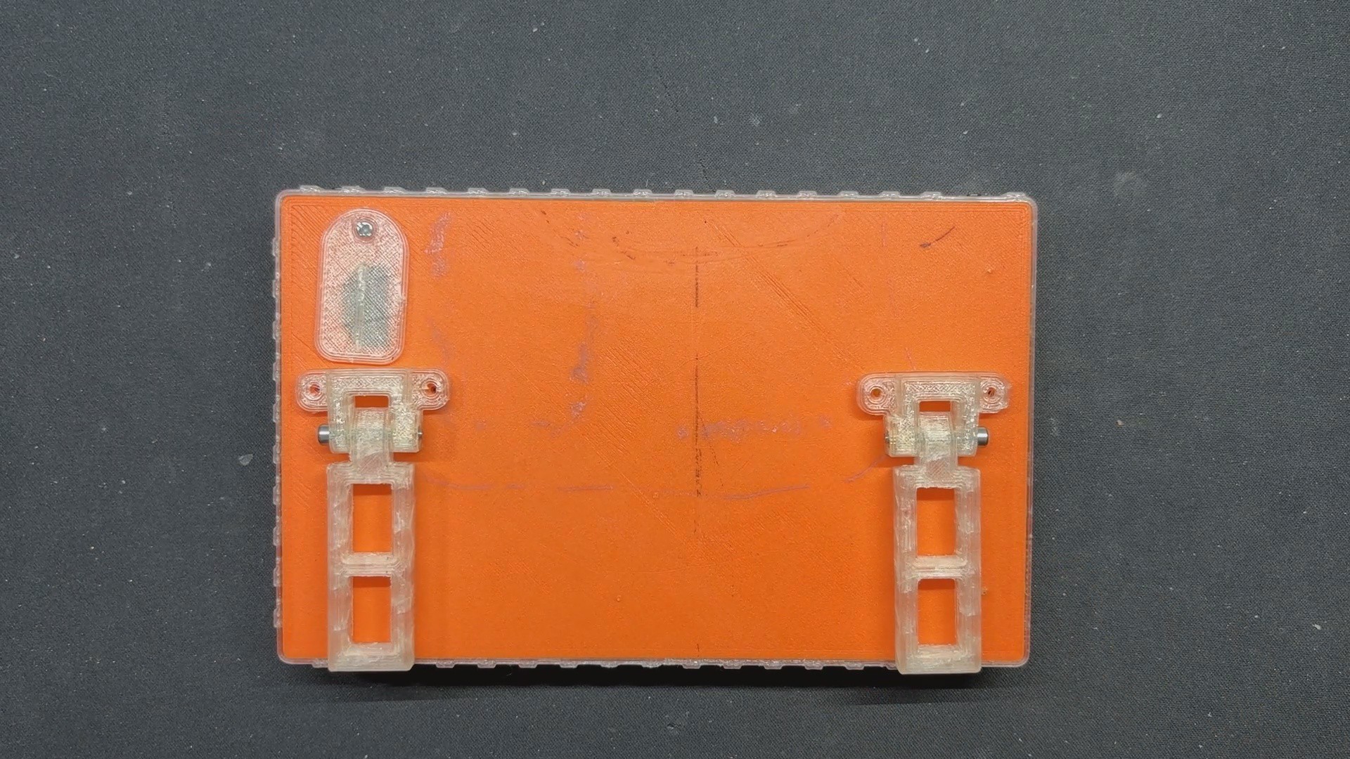
- We use two M2.5 nuts and bolts to secure the stand and its holder together.
- We then positioned the stand holder assembly on the display's rear side and tightened them both with the LID component, using two M3 screws per stand.
- Assembly has now been completed.
-
7RESULT
![]()
![]()
![]()
![]()
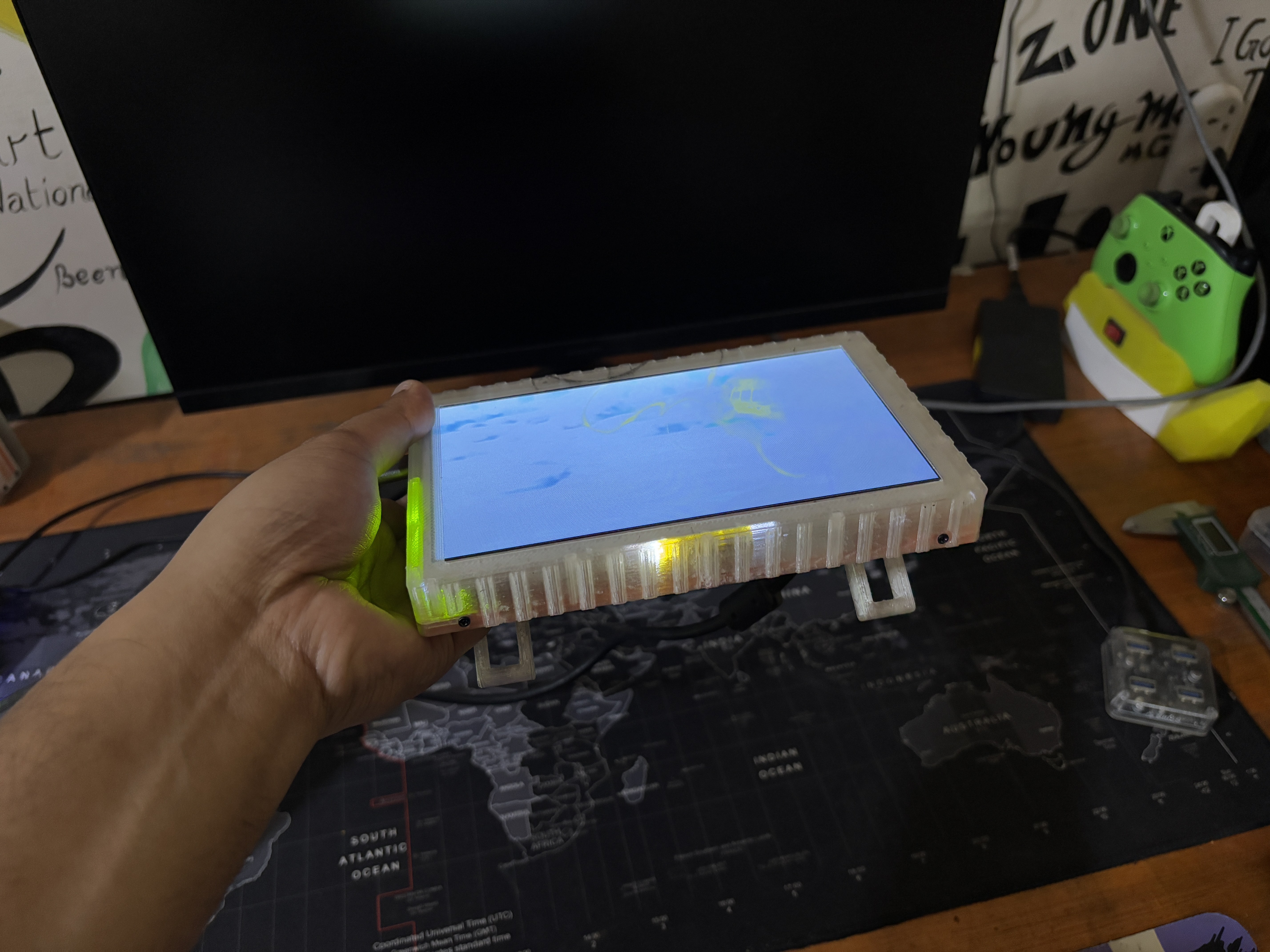
the culmination of this project is a sleek and functional 7-inch portable monitor that combines convenience with versatility. Featuring an HDMI port on the back, this monitor can seamlessly connect to a variety of devices, making it an ideal companion for both work and leisure.
The integrated battery pack ensures wireless operation, adding to the monitor's portability and ease of use. Whether you're traveling, presenting, or simply seeking a second screen, this portable monitor provides a reliable and efficient solution.
We tested this monitor by connecting it to our laptop and streaming the movie Dragon Ball Super Broly. The visuals were spectacular, as expected for an LCD panel with a refresh rate of 60 Hz. This display is rather usable, and because of its compact size, it is best used as a secondary monitor with a laptop.
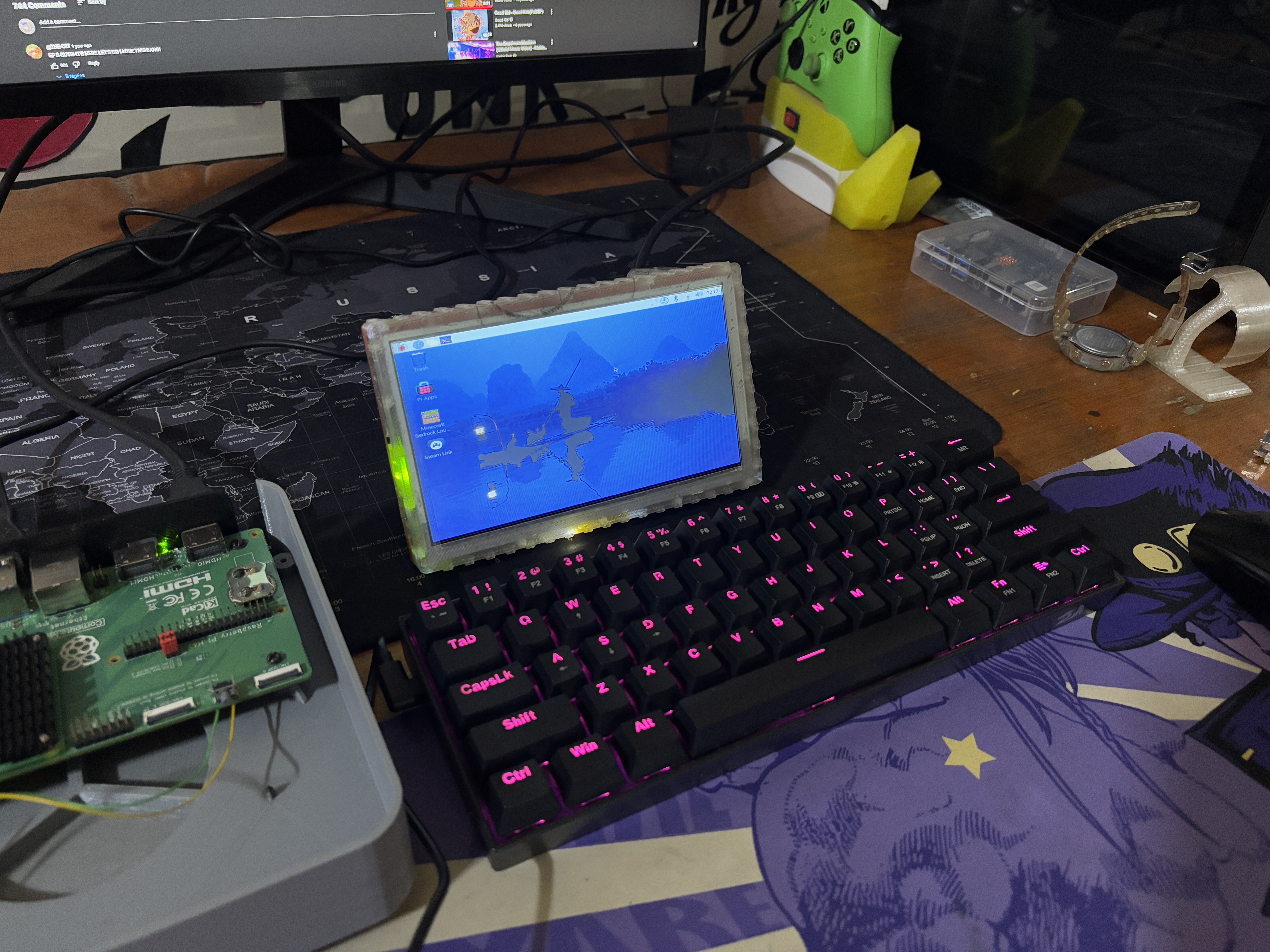
The second application for this display is with a single-board computer. We connected one of our ongoing projects, which includes a Raspberry Pi CM5 board, to our portable display, and it produces an excellent Pi display.
Overall, this project is now concluded and requires no further revision.
Leave a comment if you need any help regarding this project. This is it for today, folks.
Thanks to Seeed Studio Fusion for supporting this project.
You guys can check them out if you need great PCB and stencil service for less cost and great quality.
And I'll be back with a new project pretty soon!
Portable Display V2
A thinner version of the previously created protable display project.


Discussions
Become a Hackaday.io Member
Create an account to leave a comment. Already have an account? Log In.