-
19/05 : Worst day
05/19/2017 at 14:50 • 0 commentsReally difficult day today. Almost everything is done, we have laser cutted a plastic sheet to build a layer for the arduino card, so we can sold the arduino cards to the parts. We have also connected the switch button to the battery.
We thought that the time of flight sensor broke. So we ccould not use it in the montage anymore, and we were going to need to replace it with the ultrason sensor, if we were not able to buy it again.
One solution would be to use the ultrasons sensor, but there is still the cone problem, which makes the device useless.
We have also glued a layer to the lower arduino shell, that is going to hold the arduino card, the battery and wires.
We are a bit late because of today's mistake, but it's still possible !
-
12/05 : Last session
05/12/2017 at 14:36 • 0 commentsToday is last session. The elastic fabric is missing so we are not going to be able to fix the vibration motors to the arm, and we can't use the 3D printer. But we have to 3D print the last Shell that will protect the Arduino part.
We have modified our program so it works with the TOF sensor, and it's working ! The TOF sensor vibrates more or less according to the distance it measures. Victoire is going to work on it during the week, she will be able to modify it so it corresponds to our base idea, which is activating different vibration motors at different vibration levels according to the distance.
We have printed the upper part of the arduino shell, and it was really long..
We are going to connect all the GND (ground) port from the vibration motors to the same wire and then connect this wire to the last arduino GND port, and ethe other wire from each vibration motor will be connected to a different port from the Arduino card.
![]()
-
05/05 : 3D printing and planification
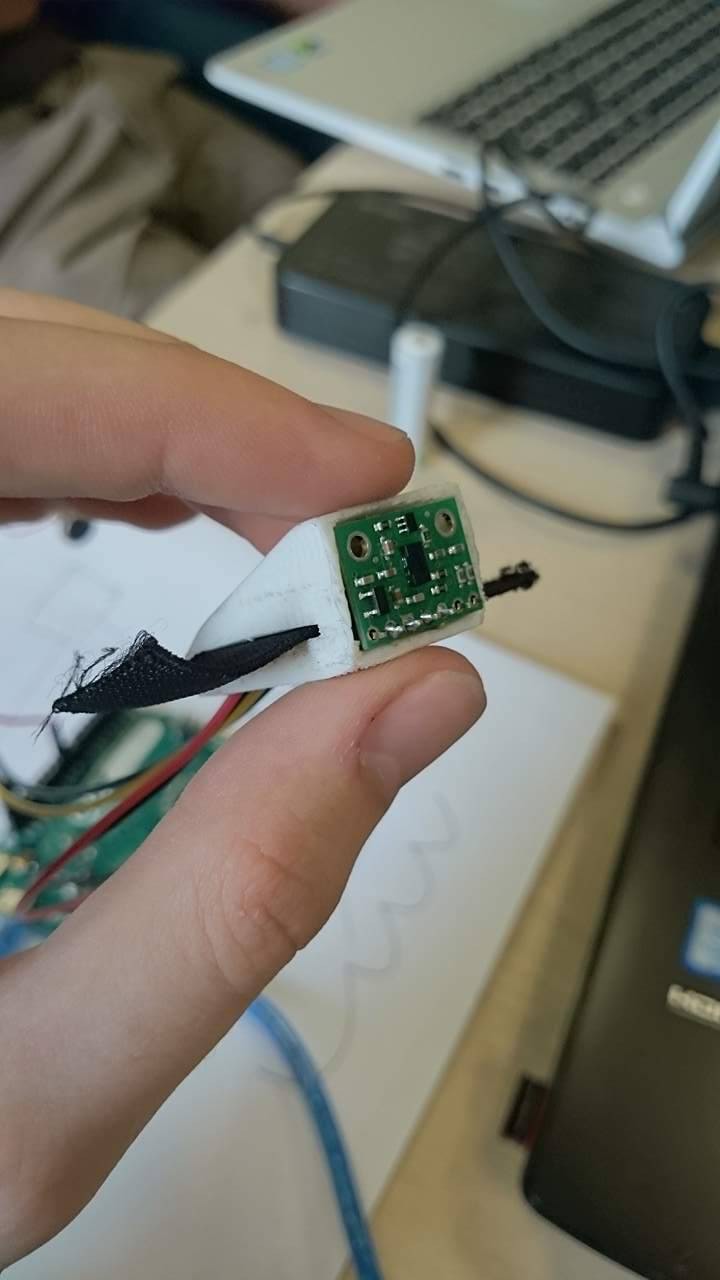
05/05/2017 at 14:55 • 0 commentsWe have printed our first piece, the shell that is going to protect the time of flight sensor.
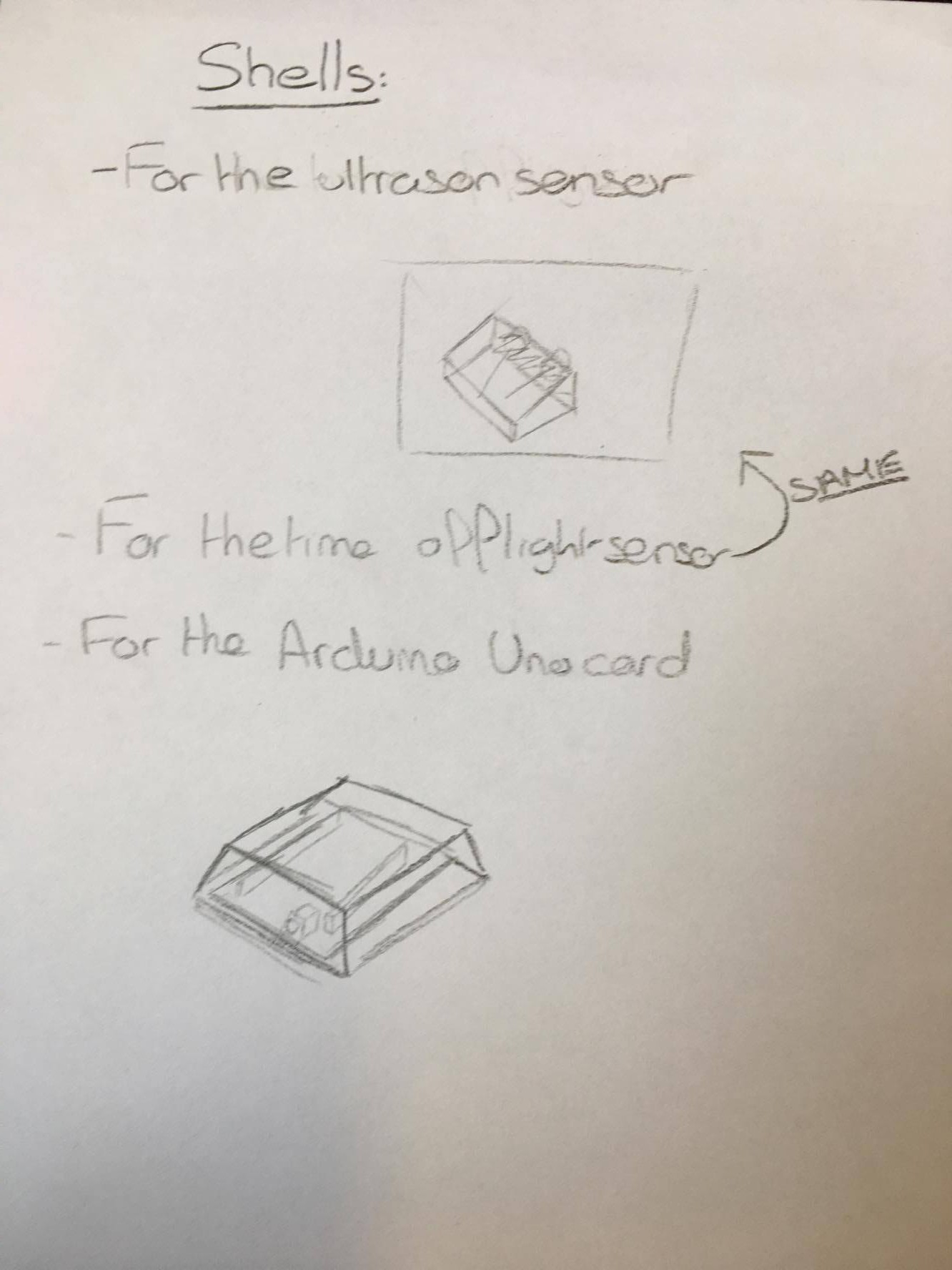
We are going to to need to work on the measures on each component to adjust the Arduino shell model, so we can finally print both of them.
So today has mainly been a day about testing. We had to test our program that detects the distance, and also to make some research for the sizes of the components.
Indeed, 4 multiplexer, an arduino card and a lot of wired are going to be inserted in this shell, so it will need a certain amount of space, although it shouldn't be too much, because we don't want the components to move in the shell.
We had to make some adjustments to the first shell after the 3D impression, to enlarge the holes for the elastic bands that will fix it to the glove and to get the wires in. It's very difficult to carve a small 3D printed part with a cutter !
We have finished modifying it so it fits with the montage. -
28/04 : Project problems.
04/28/2017 at 14:00 • 0 commentsThe project actually progress pretty slowly this week : we are missing some components for the project and we are trying to bypass them the best we can.
So for now, we are testing our device as we can with what we got.
For now, we need to produce something, so we will try to make a device that vibrates when it detects something. we are losing precision, but we expect that when the right components arrive, we will be able to make the sonar we expected.
In our actual situation, we will try to make a sonar that vibrate when it detects something without distance appreciation and connected to more or less 5 vibromotors.
-
21/04 : Components and test time !
04/21/2017 at 14:46 • 0 commentsWe have received and gathered almost all our components : there are still missing some of them, but we can at least go a bit further.
We have designed another 3D shape, the upper part of the Arduino card shell.![]()
![]() We made a few research about how we are going to make our device, and we have a new component, an arduino multiplexer, that is going to allow us to plug up to 50 (64 exactly) vibration motors, and we are going to need that so the device can be really be accurate.
We made a few research about how we are going to make our device, and we have a new component, an arduino multiplexer, that is going to allow us to plug up to 50 (64 exactly) vibration motors, and we are going to need that so the device can be really be accurate.We have also made some research about the programming stuff, and it's only going to be composed of "if loops", so it's going to be kind of easy as long as we know how to program this kind of loop.
-
21/04 : The question of the sensor
04/21/2017 at 14:35 • 0 commentsSo after a lot of research, we had to clear the question of which sensor we will use for our device. First of all, our idea was to create a device with two modes on it : an outside mode which will use the ultrason sensor and an inside mode with the Tof sensor (Time of Flight). The decision has been made because of the range of the different sensors : the ultrason one can detect to 4.5 meter and the ToF one to 2 meter.
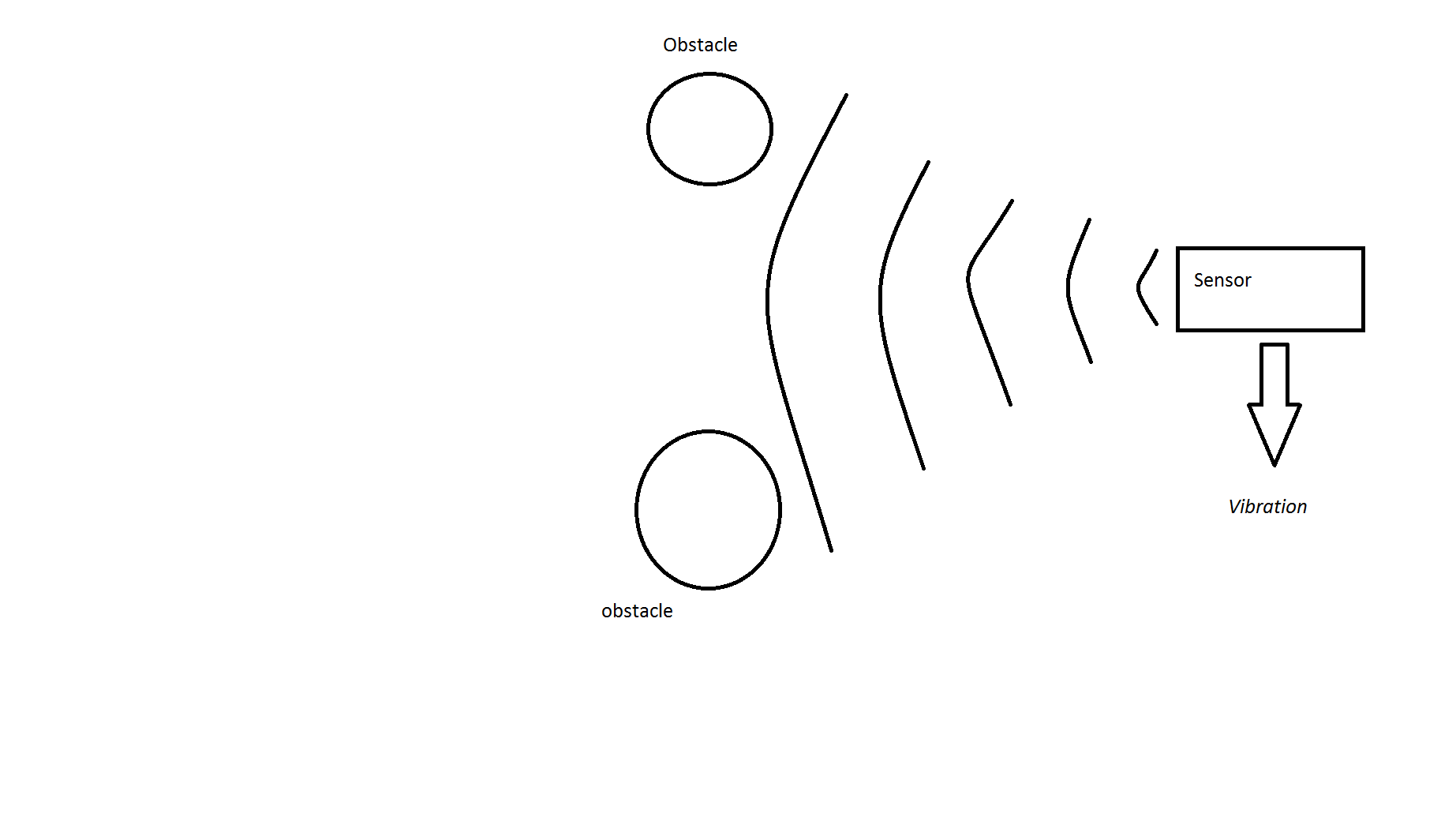
And the first problem appeared : because the cone of detection of the ultrason sensor is too wide at the end. After asking some aquitances, we cannot differentiate what is in front of us or in the extreme corner of the cone of the ultrason.
![]()
(Basic diagram of what can append and could disturb the "vision" of the holder)
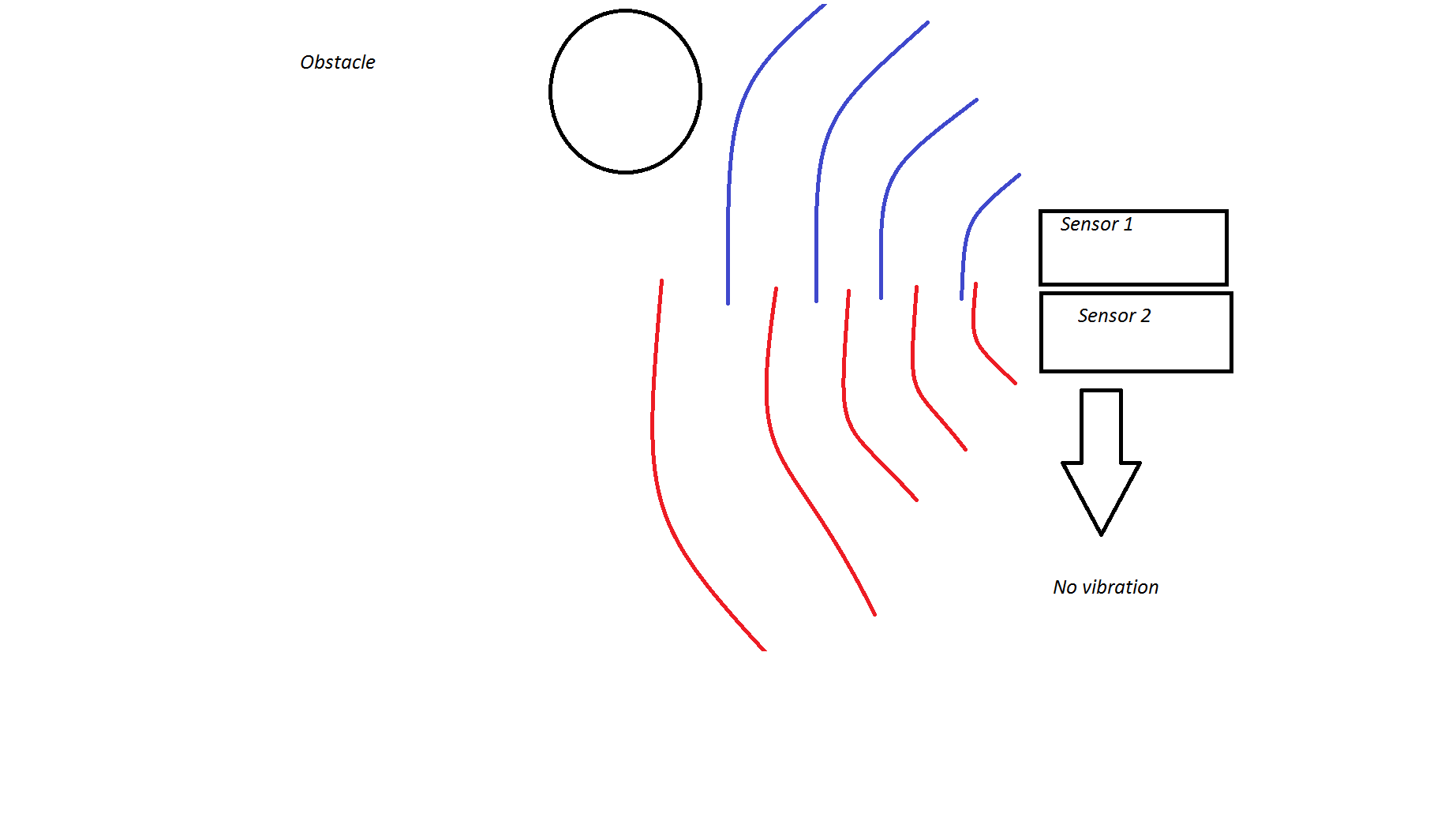
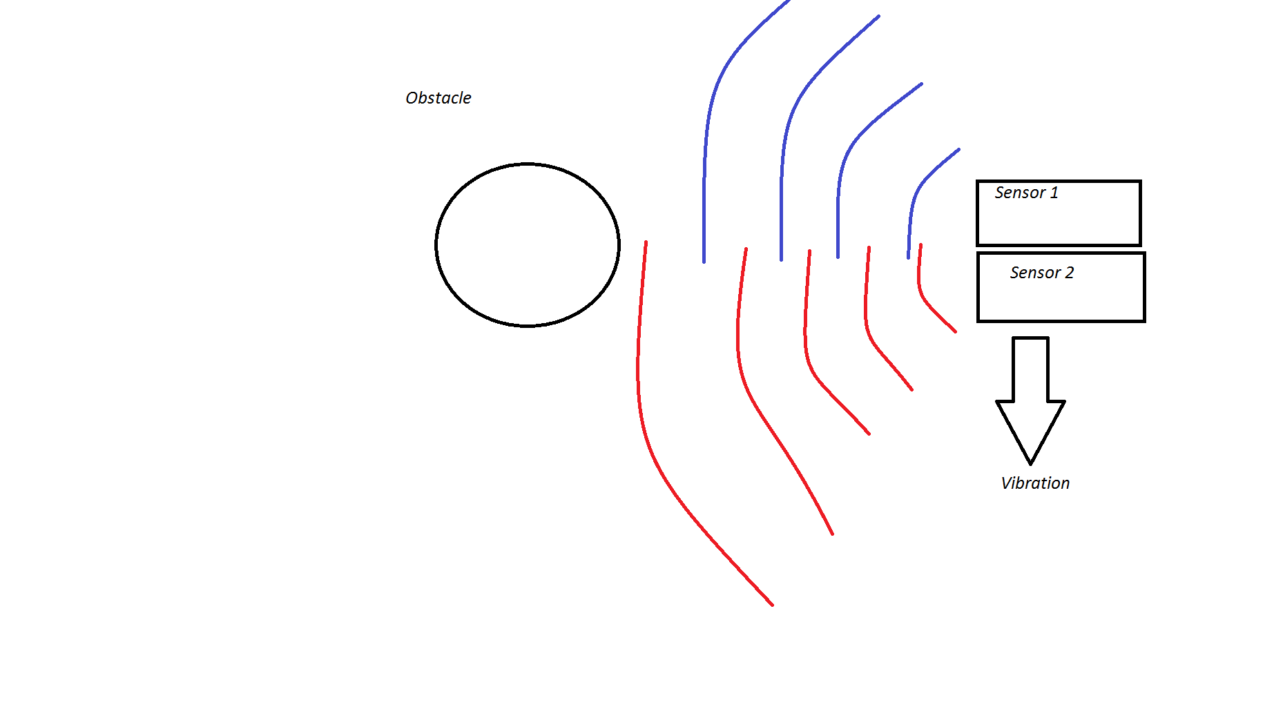
So, with the help of the teachers, we thought about triangulation.
The idea is if the two sensors detect an object, it will activate the vibration motor.
By positionning the two sensors to have a straight line, we can have a pretty accurate line of detection.
![]()
![]()
(diagrams of the triangulation)
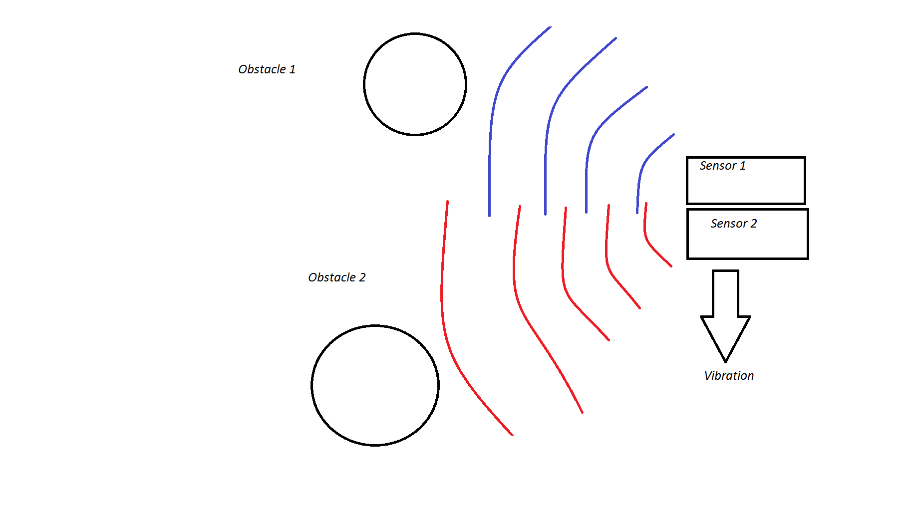
Then, after a second thought, we realized that, because ultrason sensor cannot differentiate obstacles and there localisations, if we put two obstacles in front of the extrem corner of each cone, the device will probably still vibrate, even if the obstacles are not directly in front of the two sensors.
So another problem blocked our project.
![]()
(Diagram of a potential problem which could happend. Limit of the triangulation.)
So at the end, because time is limited, we thought about give up for now the idea of two different modes on our device.
We will work only on the ToF sensor and if we have still time, and maybe come back with solutions for the ultrason sensor.
-
3D Modelisation : Step 1
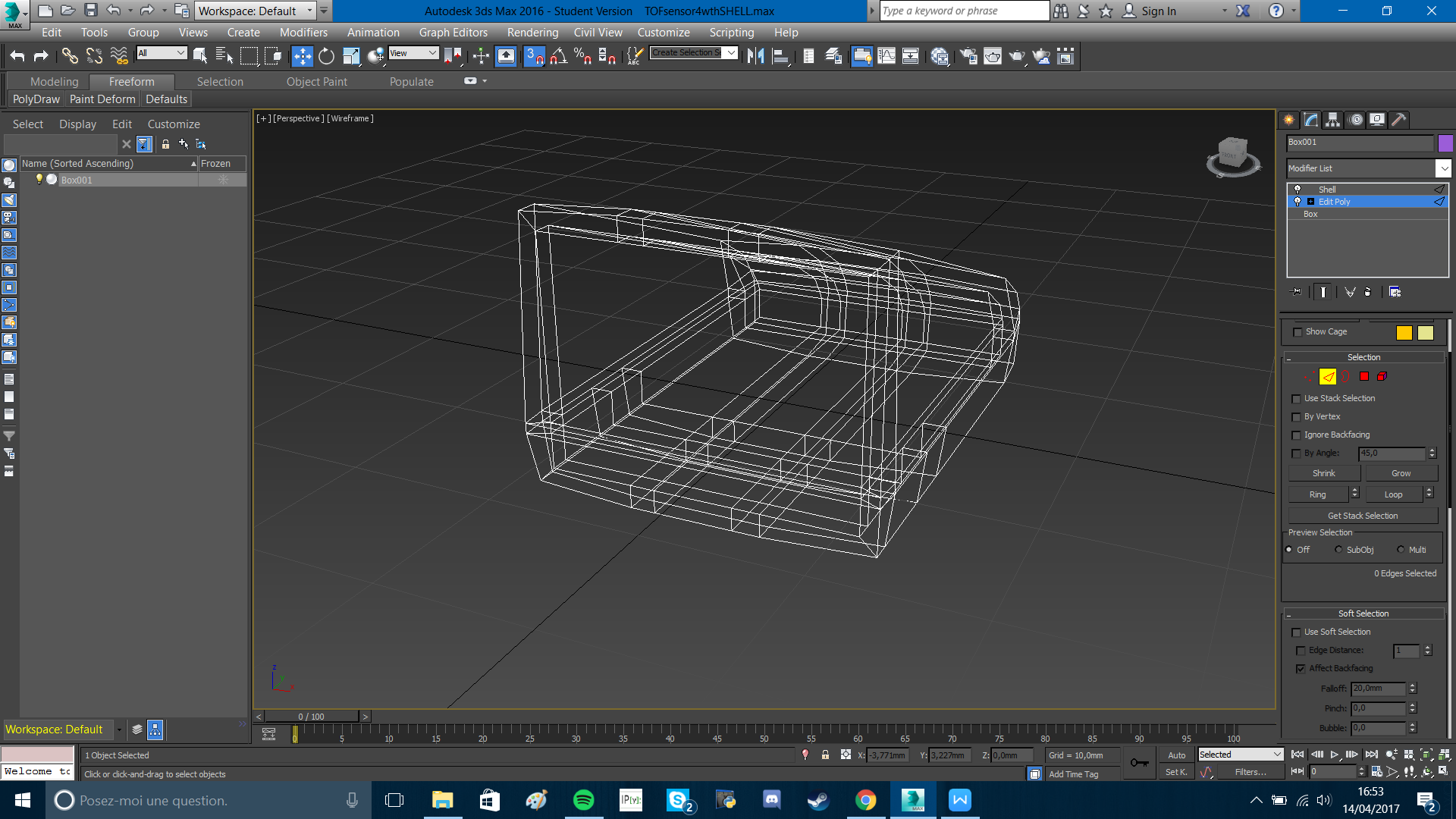
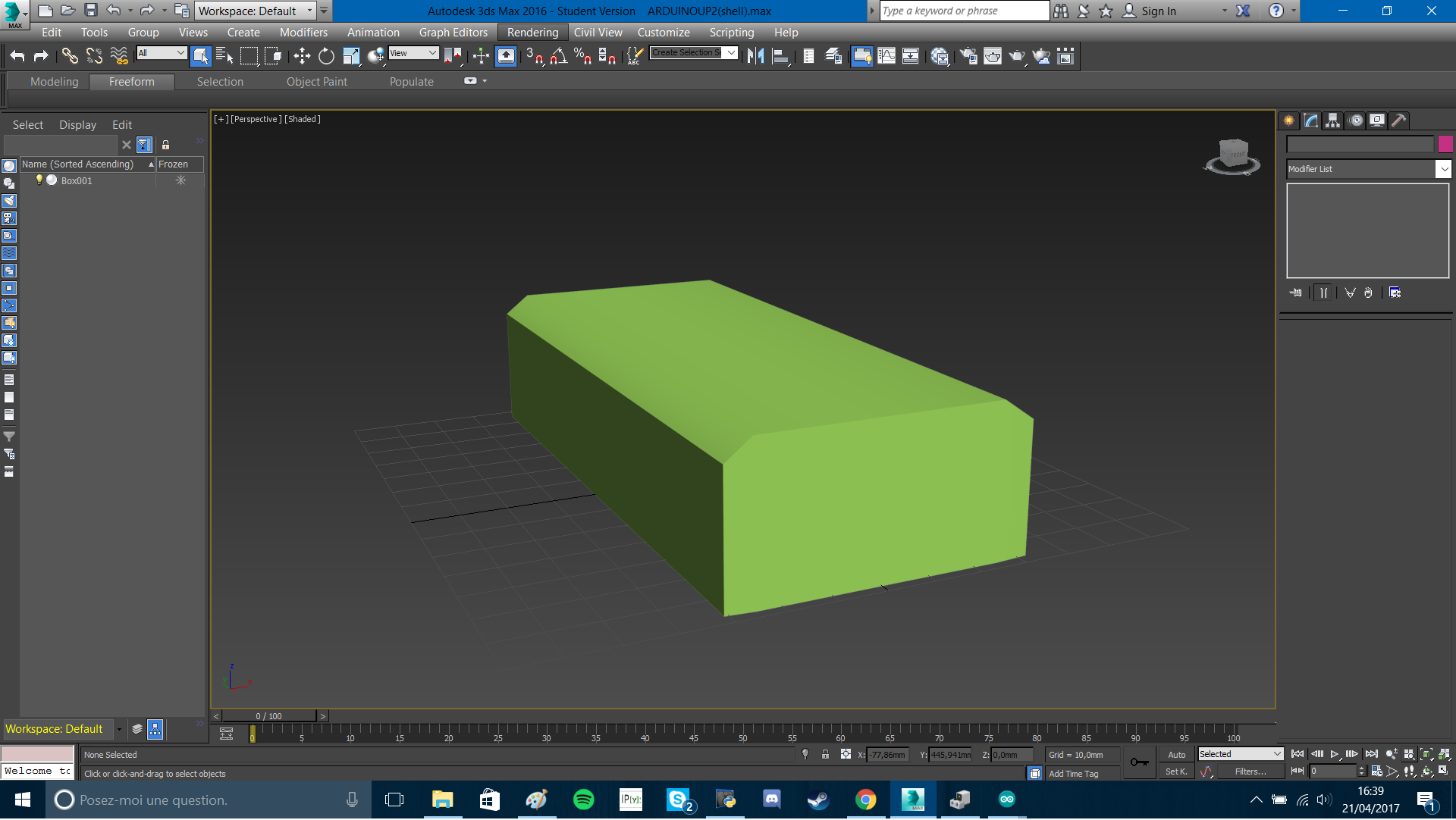
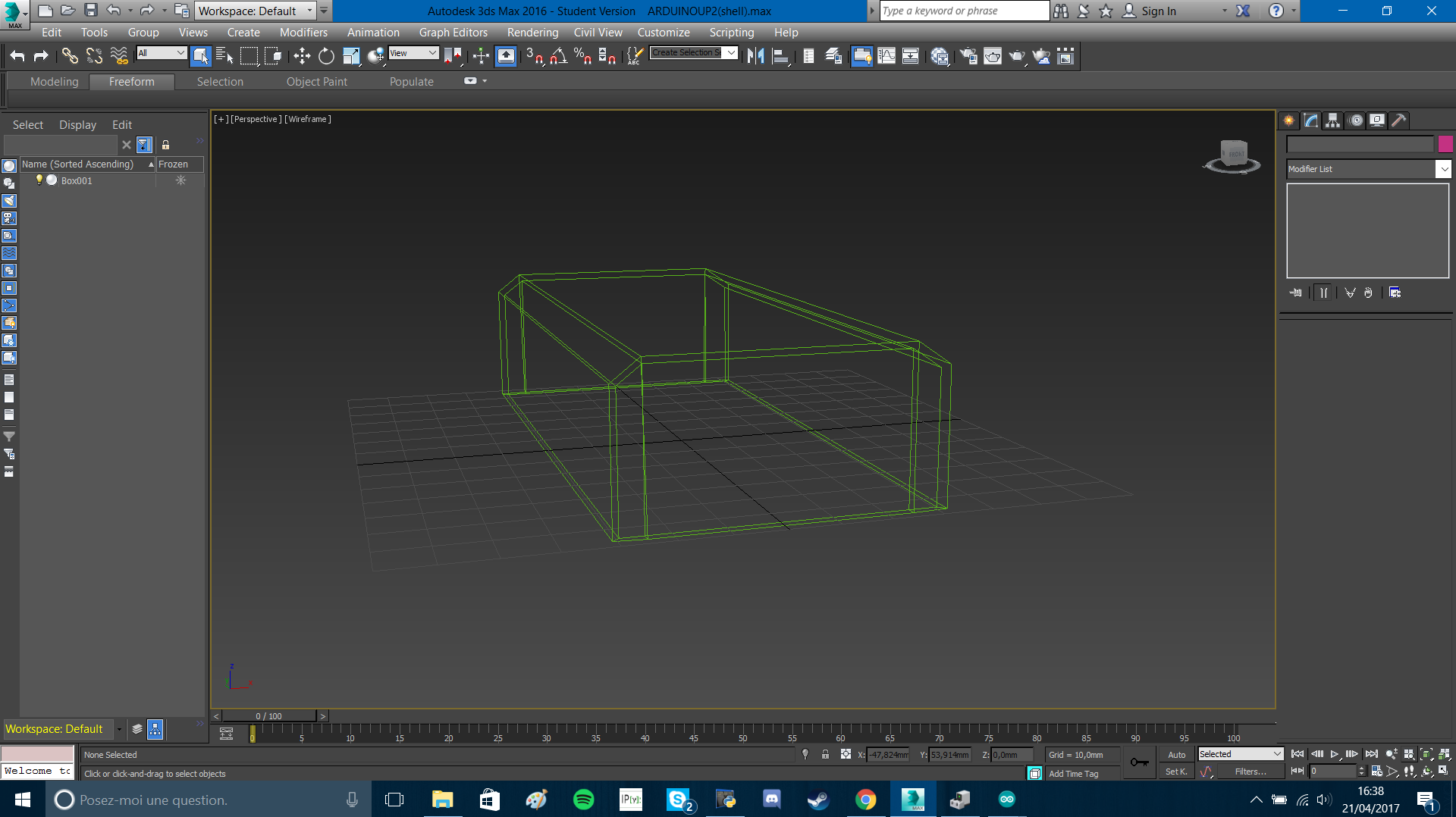
04/14/2017 at 15:07 • 0 commentsStarted to learn how to use a 3D modelisation software named 3ds Max, with the basic functions. So I could design a first model of the shell that will protect the time of flight sensor. It's tiny and subtle, perfect to be placed on the hand. Furthermore, putting it at this place will allow the user to have a greater range.
Here are some screenshots of the first shell's model :![]()
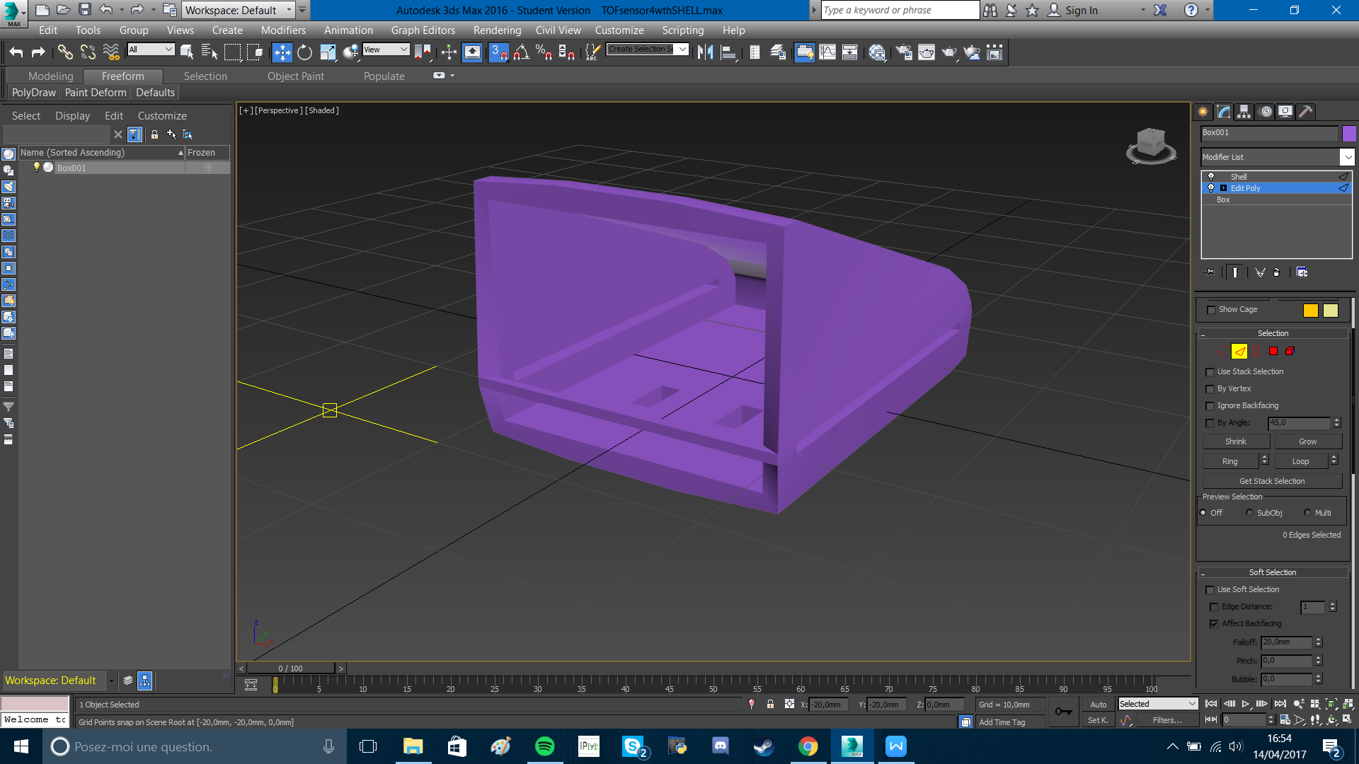
![]()
As we can see on the second picture, there are holes in the shell that are made to attach it to the glove : one slot on each side to attach it with a band. And two holes on the bottom to sew it. Just to be sure it doesn't move, for a better accuracy.
-
31/03 : Research (Programmation)
03/31/2017 at 14:35 • 0 commentsAlmost every components are missing, so we can't do that much. We chose to make more research, about programming now.
We also have decided that, indeed, we should use a time of flight sensor and an ultrason sensor. We are going to set 2 modes on our device : an interior mode, that is going to use the time of flight sensor (2 meter range for a better accuracy), and an exterior mode, that is going to use the ultrason sensor. We will need a program that reduces the cone of the ultrason sensor from an angle of 15° to an angle of almost 0° in order to use it properly.One member of the group has to focus on the time of flight sensor part, another one has to focus on the ultrason sensor : that means receiving the information and process the data.
The last member has to focus on the vibration part, that means using the data from the sensors to activate the vibration motors, depending to the received signal.
We are struggling to decide if we are going to use the ultrason sensor. We will find out after a few tests.
So now we will just need to wait for the components in order to test them.
-
24/03 - Research time
03/24/2017 at 15:03 • 0 commentsFor this day we decided to look for some informations for our project.
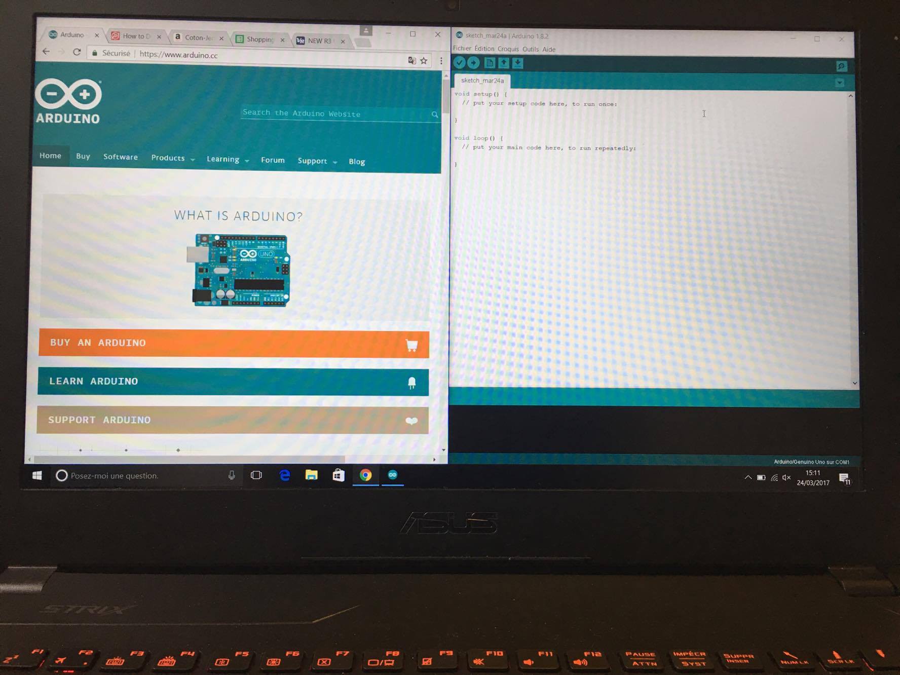
So we've decided to download the arduino software, which is going to be required for the arduino uno card. We will need to learn the C language.![]()
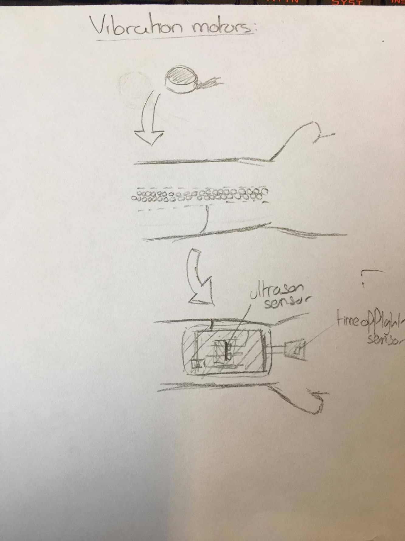
We have also worked on the design of our device, how it will be arranged, and how we are going to protect the breakable parts (arduino card, ultrason sensor, time of flight sensor).
![]()
![]()
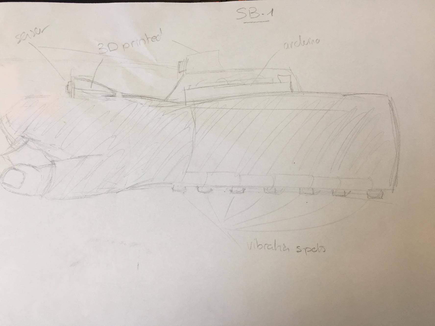
To put it in a nutshell, the wristband should look like that :
![]()
As you can see on this drawing, we are thinking about using also an ultrason sensor that will be placed on the top of the arduino uno card's shell (in addition of the time of flight sensor)
It will allow us to improve the range and the radius of our device.
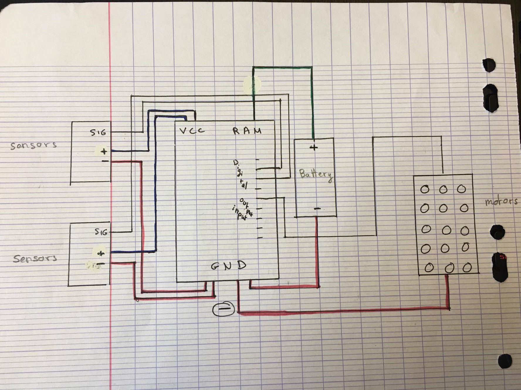
We also have made a plan of the connections in our device :
![]()
-
An important step in components research
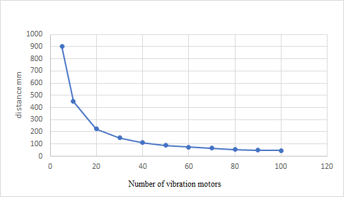
03/23/2017 at 18:58 • 0 commentsWe have been struggling with the number of vibration motors we should put in our device, and we have decided that the most logical choice was to put 50 in it. Indeed, it would give us a 90 mm scale interval, which is pretty accurate, and we could even improve this accuracy by, for instance, setting 2 levels of vibration, which would give us a 45 mm scale level.
So the user will be able to detect the difference of distance between 2 objects that are 9 cm far (max).![]()
Sonar Blind Project
The Sonar Blind Project tends to replace the blind mans canes with a wristband that works with sonar concept.
 We made a few research about how we are going to make our device, and we have a new component, an arduino multiplexer, that is going to allow us to plug up to 50 (64 exactly) vibration motors, and we are going to need that so the device can be really be accurate.