 JP Alfonso
Project Overview
The Kaossilator requires 4.5V DC for operation, but most portable power sources like USB power banks provide 5V DC. Supplying 5V directly can risk damage to the device. This project aims to drop the voltage from 5V to 4.5V by leveraging the properties of diodes—specifically their forward voltage drop.
How It Works
Diodes allow current to flow in one direction and naturally drop a small amount of voltage (forward voltage drop) when current flows through them. By placing one or more diodes in series with the power line, you can reduce the voltage to the desired level.
- Schottky Diodes are ideal because they have a lower forward voltage drop (~0.2V to 0.5V), minimizing energy loss and heat generation.
- The target is to drop 0.5V from the 5V supply, which typically requires 1–2 Schottky diodes in series, depending on the diode's specifications and actual performance under load.
Materials for Part 1
- Schottky Diodes (SS34): Chosen for their reliability and low voltage drop.
- 1N5408 Diodes: A secondary option for comparison; these have higher current capacity but may drop more voltage (~0.7V).
- USB to DC Cables:
- Initially ordered cables with 5521 connectors (commonly used for other devices).
- Realized the Kaossilator uses a 3.5x1.35 mm connector and corrected the order.
- Multimeter: For measuring voltage drop across each diode and verifying the output voltage.
- Soldering Iron: To securely connect the diodes to the power cable.
Steps Taken in Part 1
- Research and Component Selection:
- Determined the required voltage drop and current capacity.
- Selected diodes based on their specifications (SS34 and 1N5408 for testing).
- Identified the Correct DC Connector:
- The Kaossilator KO-2 uses a 3.5x1.35 mm input, which is different from the initially ordered 5521 connectors.
- Adjusted the order to match the Kaossilator’s requirements.
- Prepared Tools:
- Ensured I had the necessary tools, including a multimeter and soldering iron, for prototyping and testing.
Challenges in Part 1
- Connector Mismatch:
- Misordered the wrong size (5521 connectors). This delayed progress but served as a valuable reminder to double-check device specs.
- Testing Environment:
- Ensuring the testing process mimics real-world usage, including current draw during live performance conditions.
Next Steps in Part 2
- Test Voltage Drop:
- Measure the voltage drop of each diode using a multimeter while connected to a 5V source.
- Determine the optimal number of diodes in series to achieve ~4.5V output.
- Prototype Assembly:
- Solder diodes into the power cable and test stability with the Kaossilator under load.
Why It’s Important
This mod allows musicians to use portable power banks with their Kaossilator for extended live performances in outdoor or unconventional venues. By documenting this process, others can replicate it for similar devices with strict power requirements.


 MagicWolfi
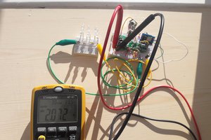
 Azri Jamil
A brand new Alkaline cell can have a voltage of 1.7V - I would not be concerned with giving the Kaossilator 5V directly. there is no circuitry inside it that uses the 4.5V directly, so giving it 5V is just fine and dandy i'm sure.