 Michael Perrone
The geometry is designed to move through the fluid with low resistance in one direction and high resistance in the other. This resistance corresponds with the force the pump exerts on the fluid. Our design attempts to maximize the difference in force applied to the fluid in the two directions. This asymmetry is produced in two ways.
The first is the asymmetric force applied by a push-pull solenoid motor on our Tesla Valve like geometry. It provides a quick pulling force followed by a slower returning force from the spring. The faster stroke forces more water to move with the geometry instead of moving around it, causing large resistance. Additionally, the higher velocity increases the fluid's turbulence and therefore resistance.
Second, the design of the geometry is asymmetric. On the aft stroke, as shown in Fig. 1, the fluid can smoothly flow around the geometry.
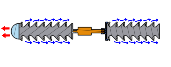
Figure 1: Aft Stroke.
In the Forward stroke, Fig. 2, the opposite is true. The fluid is redirected causing a larger amount of turbulence and flow resistance.
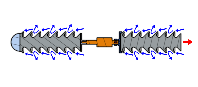
Figure 2: Forward Stroke.
We also designed a similar geometry where the fluid flow is completely internal to the structure, Fig 3. This design was found to provide slightly less force but may work better for certain applications.
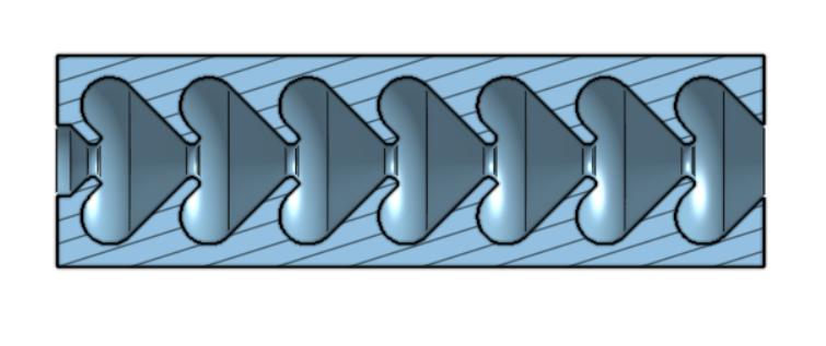
Figure 3: Design with internal flow.
 Supercell
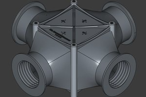
 TRAN.VINH.QUANG
 David Shelenev
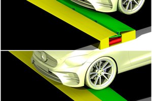
 Anteneh Gashaw