 Michael Perrone
-
1Bill of Materials
Tools:
- Band saw or anything that can cut the plastic tube
- Soldering equipment
- Hot glue gun
Mechanical:
- 3D printed components, the .STEP files are in the files section. Note the different versions for the internal and external design.
- 2 X Tesla Pump
- Motor-Pump attachment piece 1 and 2
- Motor C-Clamp
- Solenoid motor
- 2 X ⅛” X 6” Wooden sticks
- Plastic Tube
- M3 X 10mm screw
- Water Soluble dye
- Scotch Tape
- Gaff Tape
Electrical:
-
2Mechanical Assembly
Please watch the demonstration video for an example of this process.
- Solder longer wires onto the motors existing wires to make it easier to use.
- Attach the C-Clamp to the solenoid motor and tighten with screw.
- Force the wooden sticks through the holes in the C-clamp. The holes should be about 0.15mm wider than the wooden sticks for a tight fit.
- Cut your tube in half and make 4 notches for the wooden sticks to be flush with the edge and 1 notch to insert the dye.
- Use Hot glue to attach the Motor-Pump attachment pieces to the Tesla Pump. Make sure to orient the geometry so the forward, high resistance stroke will be pushed by the force of the motor when in the high state, not the return from the spring.
- Attach the Tesla valve pieces to your motor.
- Place the motor into the cut tube and then tape the other side to enclose the device.
-
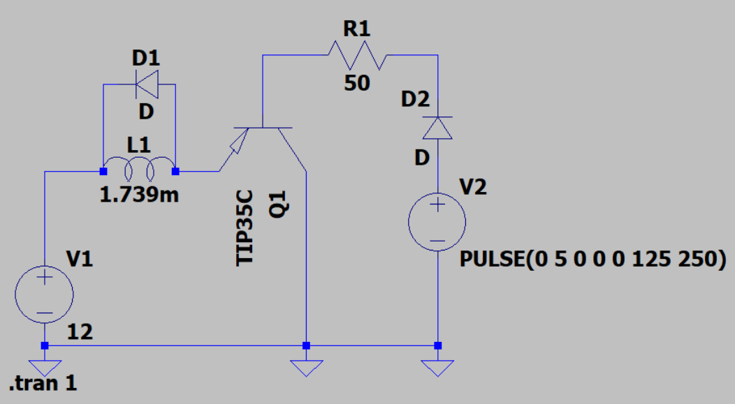
3Electrical Design
The pump is powered by a square wave provided to the solenoid motor. The square wave has an amplitude of 12V, a frequency of 4 Hz and a duty cycle of 50%.
Set up your circuit according to the schematic below.
The circuit includes:
- V1: Benchtop power supply providing 12V DC.
- V2: Arduino Mega 2560 generating a 4 Hz square wave via pin 9.
- L1: Solenoid motor.
- Q1: TIP35C Transistor to amplify the Arduino signal.
- D1/D2: 1N4007 Diodes for protection against voltage spikes.
- R1: 50Ω resistor to limit base current to the transistor.
-
4Code
The Arduino Mega 2560 is running this script to generate the square wave. We found the device functions best at 4 Hz, this frequency allows the motor to exhibit its full stroke length.
const int motorPin = 9; // Pin connected to the transistor base
const int frequency = 4;
const int delay_time = (1000/frequency)/2;

void setup() {
  pinMode(motorPin, OUTPUT); // Set pin as output
}

void loop() {
  digitalWrite(motorPin, HIGH); // Turn motor ON
  delay(delay_time);

  digitalWrite(motorPin, LOW);  // Turn motor OFF
  delay(delay_time);
}
Sonic Propulsion experiments
Using Tesla Valves to rectify AC fluid flows
Discussions
Become a Hackaday.io Member
Create an account to leave a comment. Already have an account? Log In.