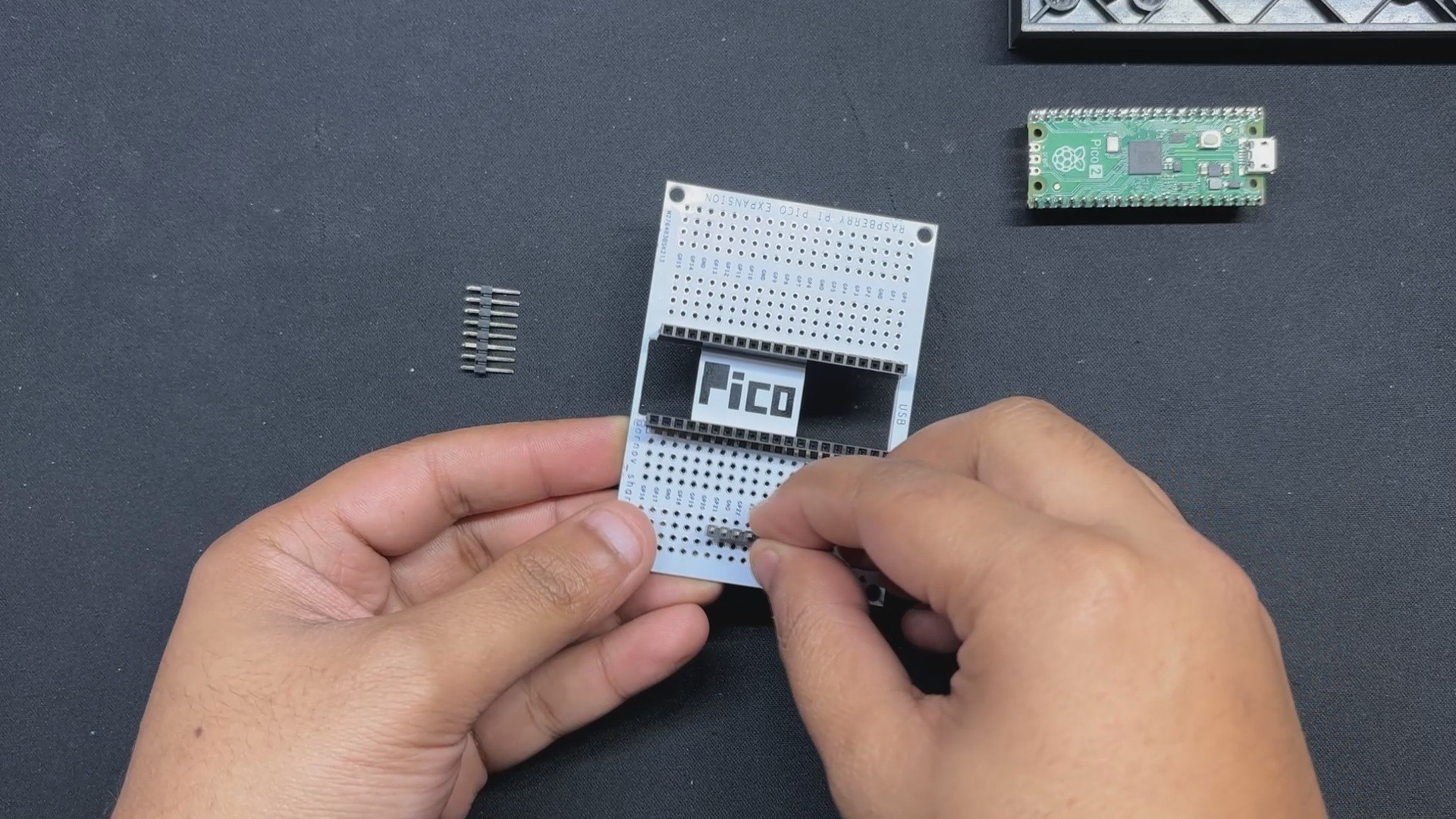
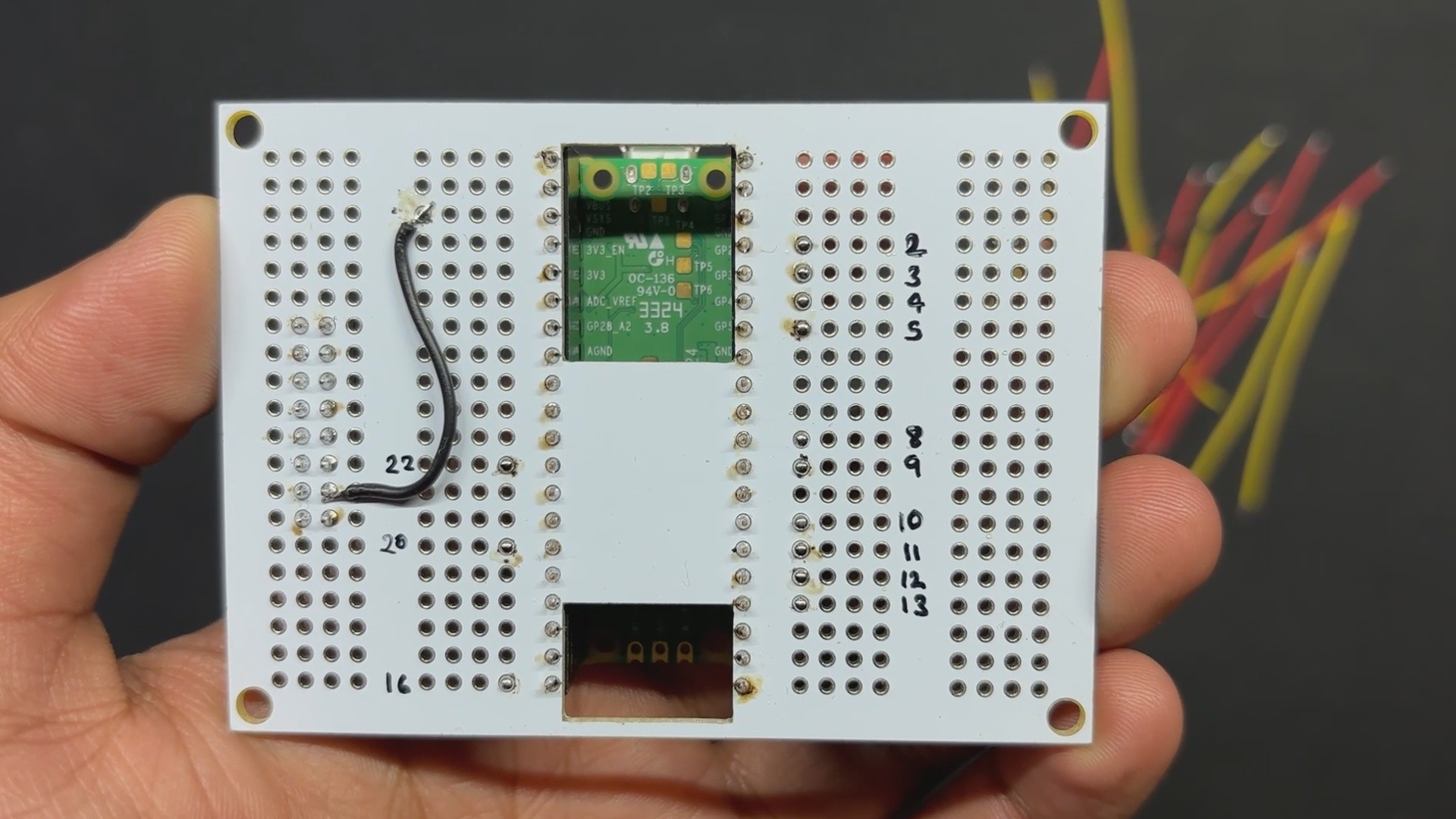
First, we attach the two 20-pin female header pin connectors to the Pico footprint's two pads. Next, we attach the two 8-pin male header pins to the board's left side. The purpose of these male header pins is to connect the PICO to the LED matrix IO connector.
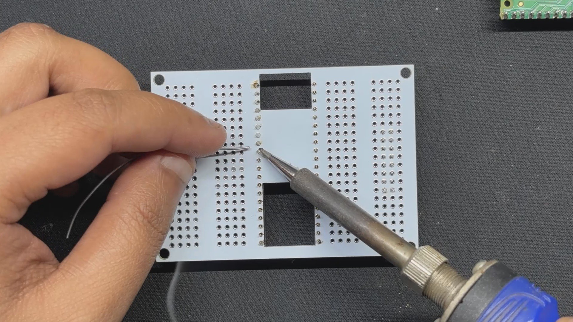
We soldered all of the male and female connector leads that were added to the expansion board from the circuit's bottom side using a soldering iron.
2
WIRING
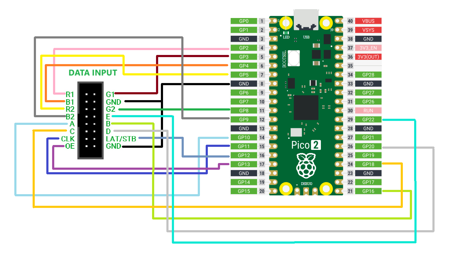
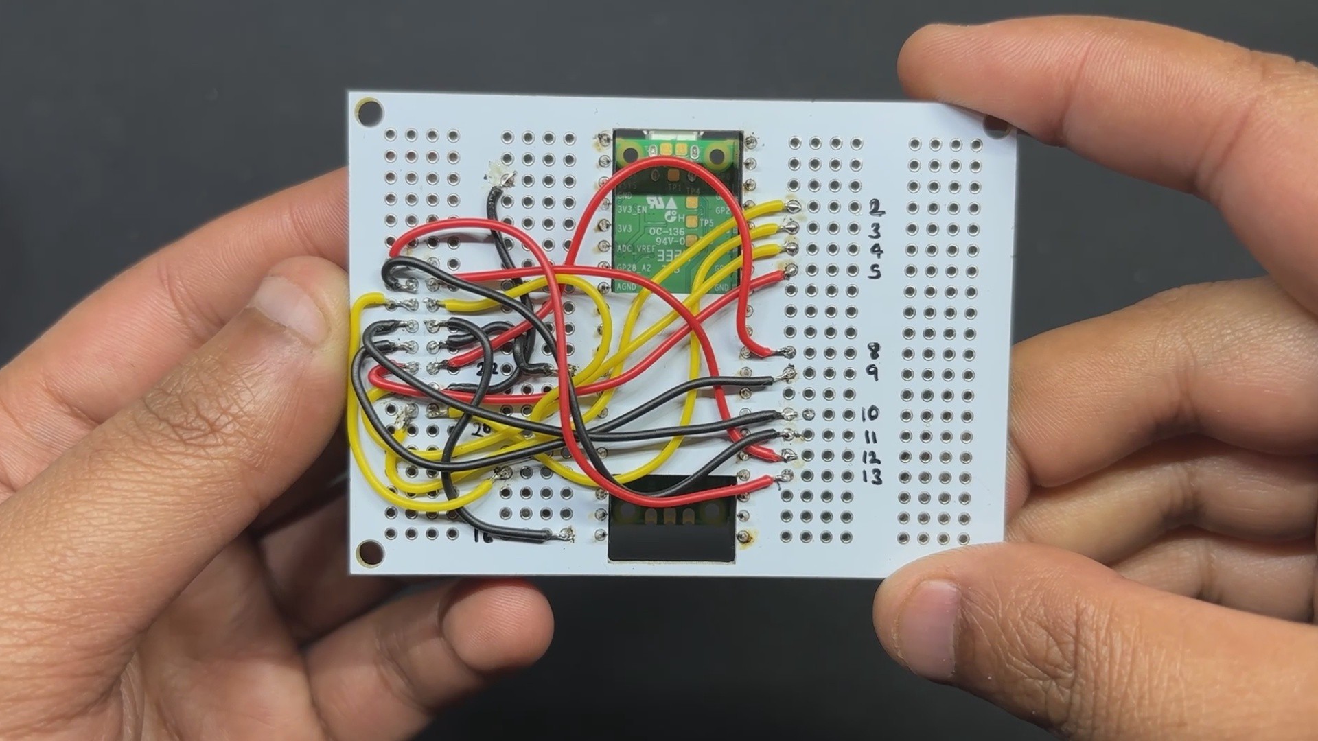
Following the provided wiring diagram, we begin the wiring process by first using a jumper wire to connect the GND pin of the matrix I/O pins to the GND of the PICO.
In the identical way, we connected the I/O pins of the matrix, which include R1 to GPIO2, G1 to GPIO3, B1 to GPIO4, R2 to GPIO5, G2 to GPIO8, B2 to GPIO9, A to GPIO19, B to GPIO16, C to GPIO18, D to GPIO20, E to GPIO22, CLK to GPIO11, LAT/STB to GPIO12, and OE to GPIO13.
3
BUCK Converter Circuit
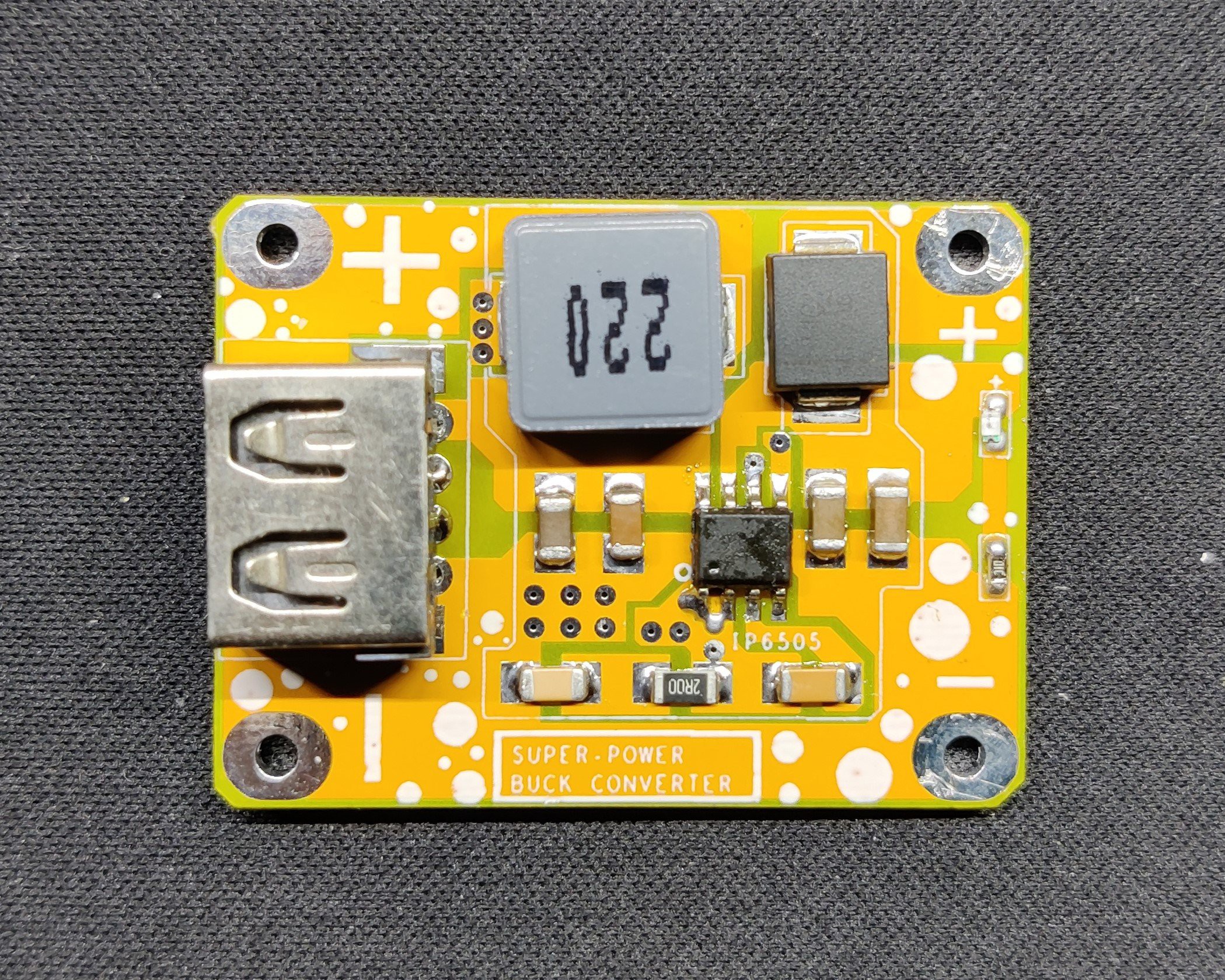
We are using one of our earlier projects, the SUPER POWER BUCK CONVERTER BOARD, which was a power module that could provide voltages ranging from 3V to 12V depending on the source supplied, as the power source for the Matrix and PICO. The input voltage in this instance is 12V, and the supply voltage is 5V.
This module is based around the IP6505, a step-down converter with an inbuilt synchronous switch that can handle an output of up to 10A for fast charging protocols.
Check out this project article for more information.
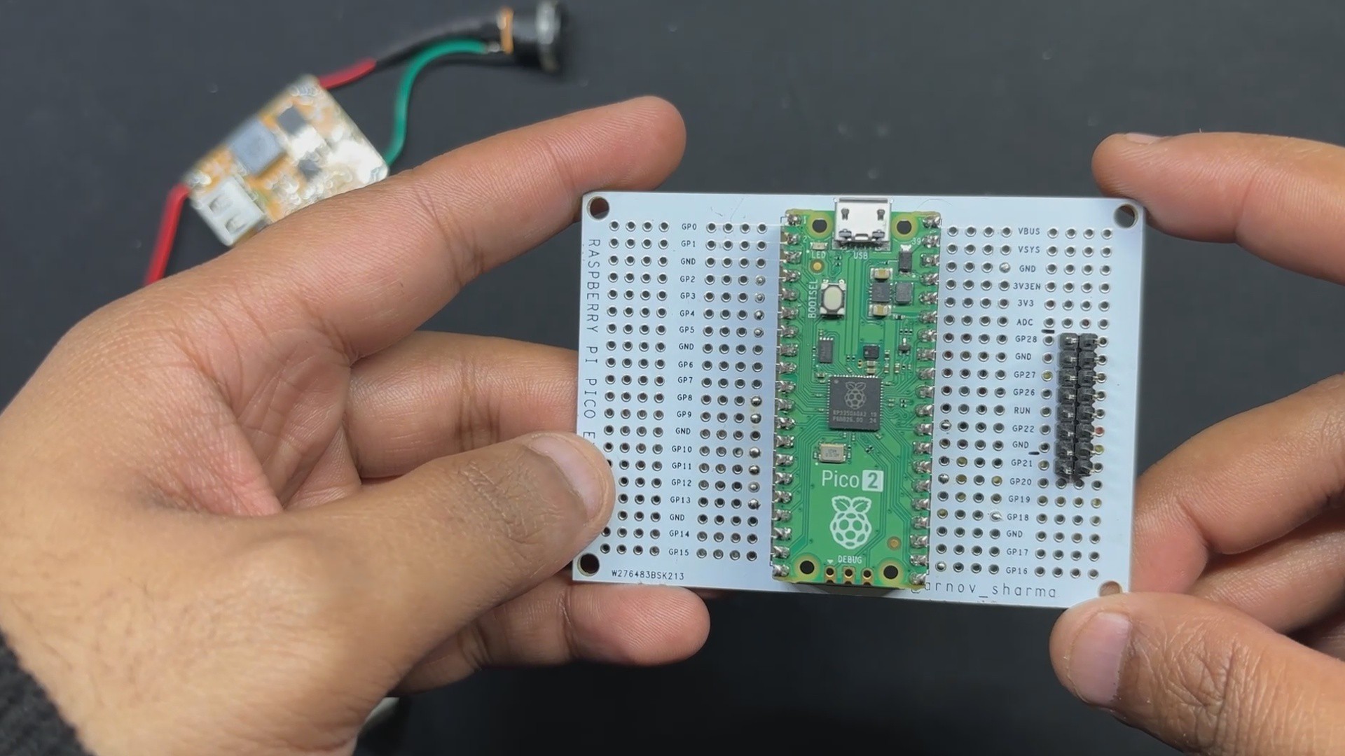
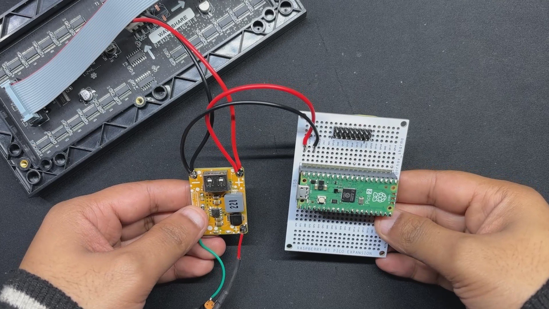
We connected the output of the Buck converter with the PICO 2's VBUS and GND pins, which will be used to power the microcontroller.
4
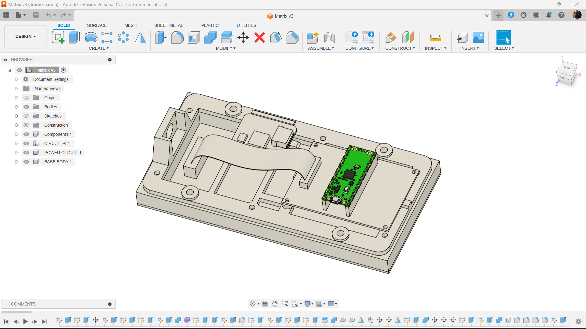
Frame Design
We created a frame that is fastened to the rear of the Matrix Panel with M2.5 threaded inserts on the Matrix. This frame was designed with a DC barrel jack holding section on one side and the PICO 2 circuit and Buck converter module on the other.
This entire frame design was created in FUSION 360, and the mesh file was exported. It was then printed in ORANGE PLA using a 0.5mm nozzle, a 0.2mm layer height, and 25% Gyroid Infill.
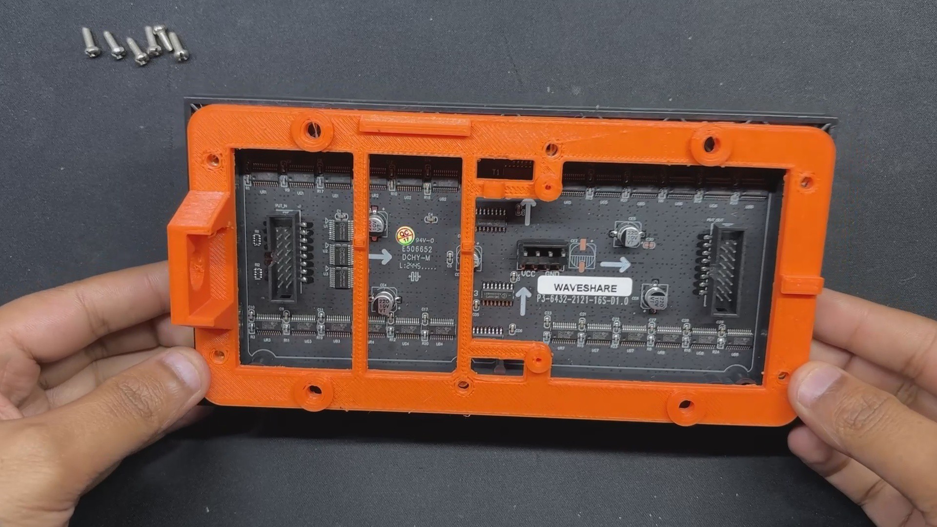
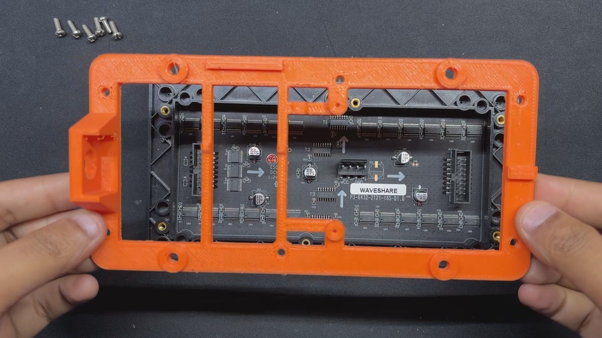
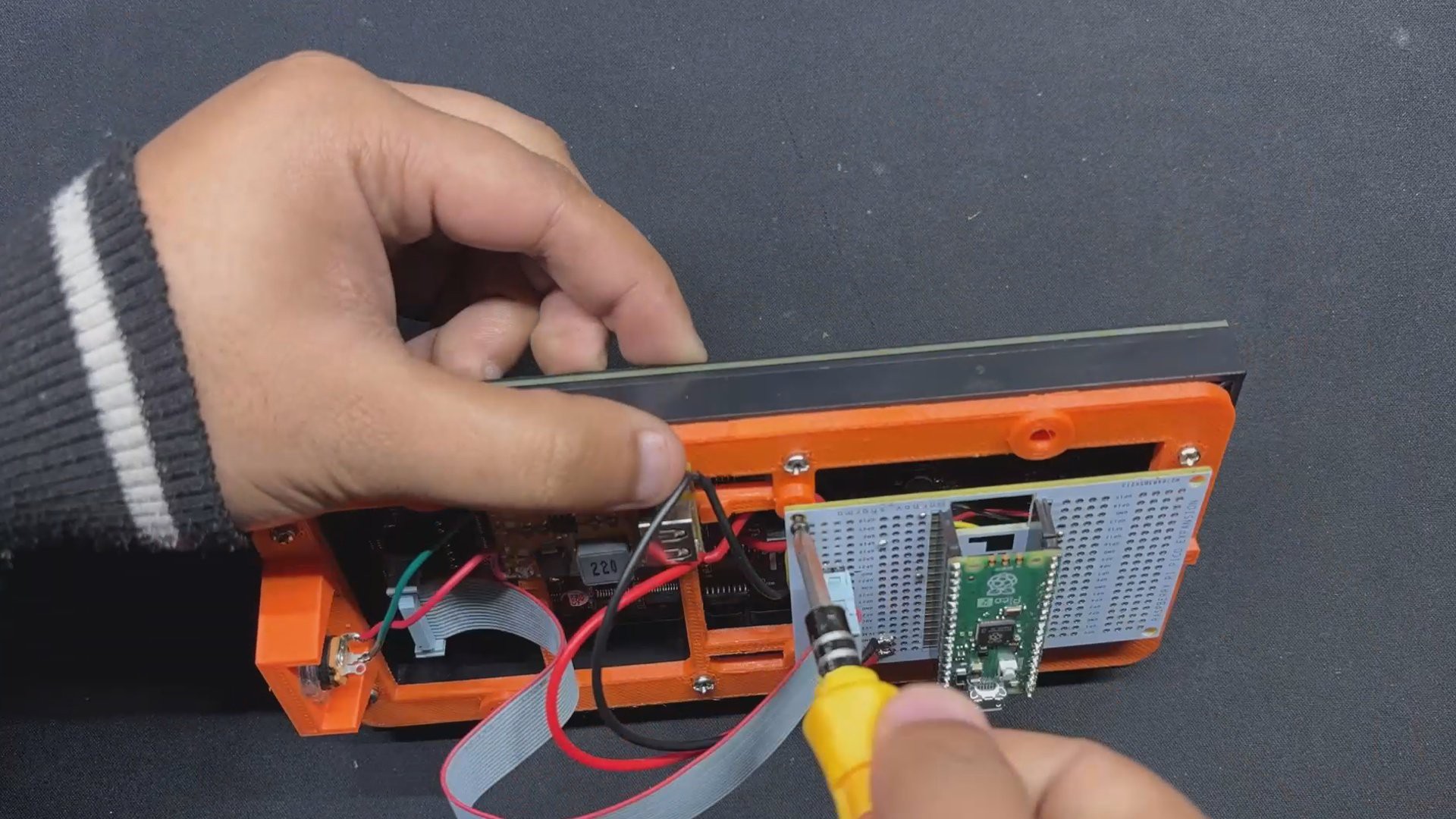
After placing the frame on the back side of the matrix panel, we install six M2.5 bolts in the mounting holes to start the frame assembly process.
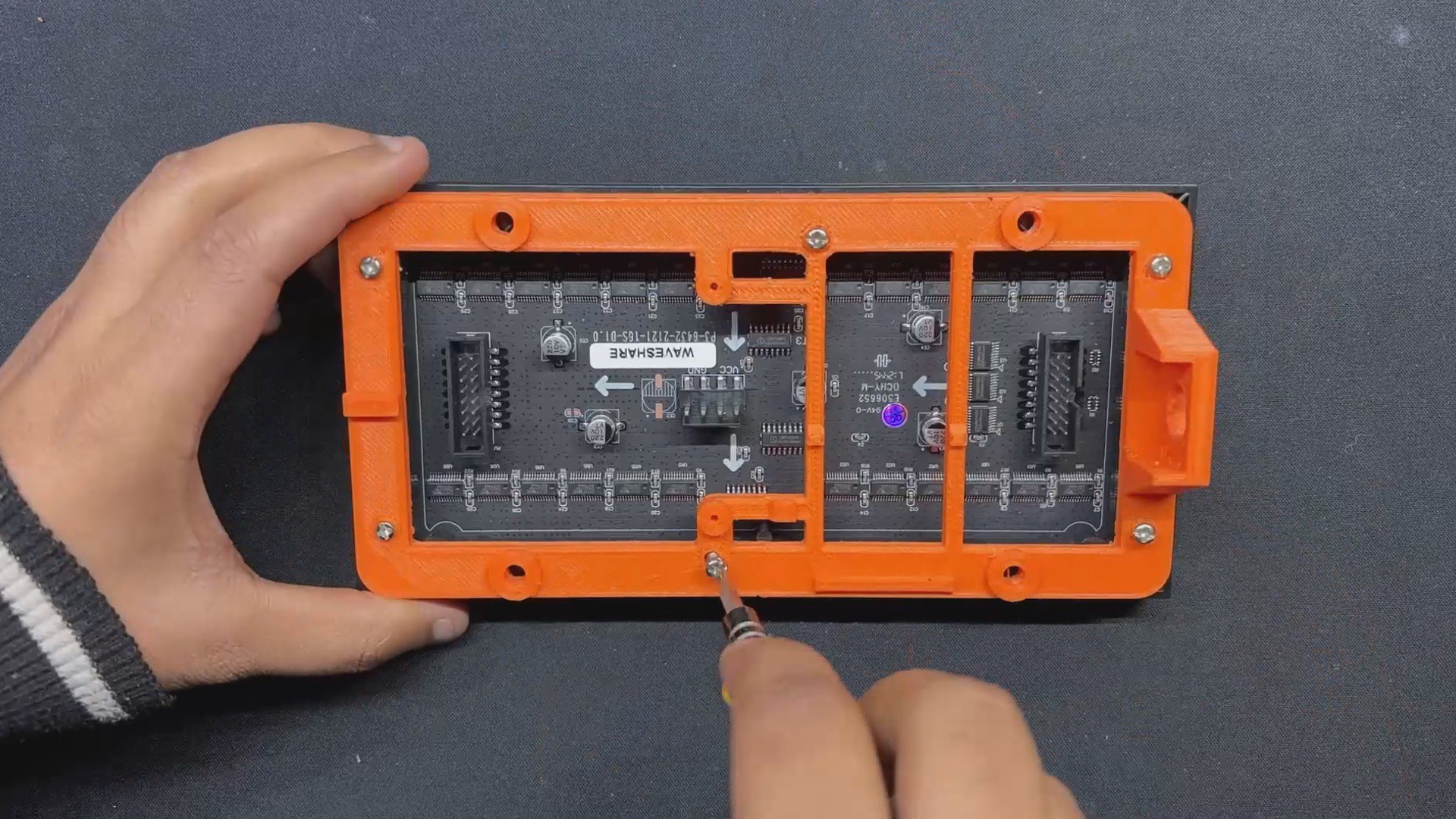
After that, we use a screwdriver to tighten every screw, securing the frame with the matrix.
5
Matrix Assembly Process
Using a soldering iron, we join the Buck converter's output pins to the matrix board's VCC and GND to start the matrix assembly process.
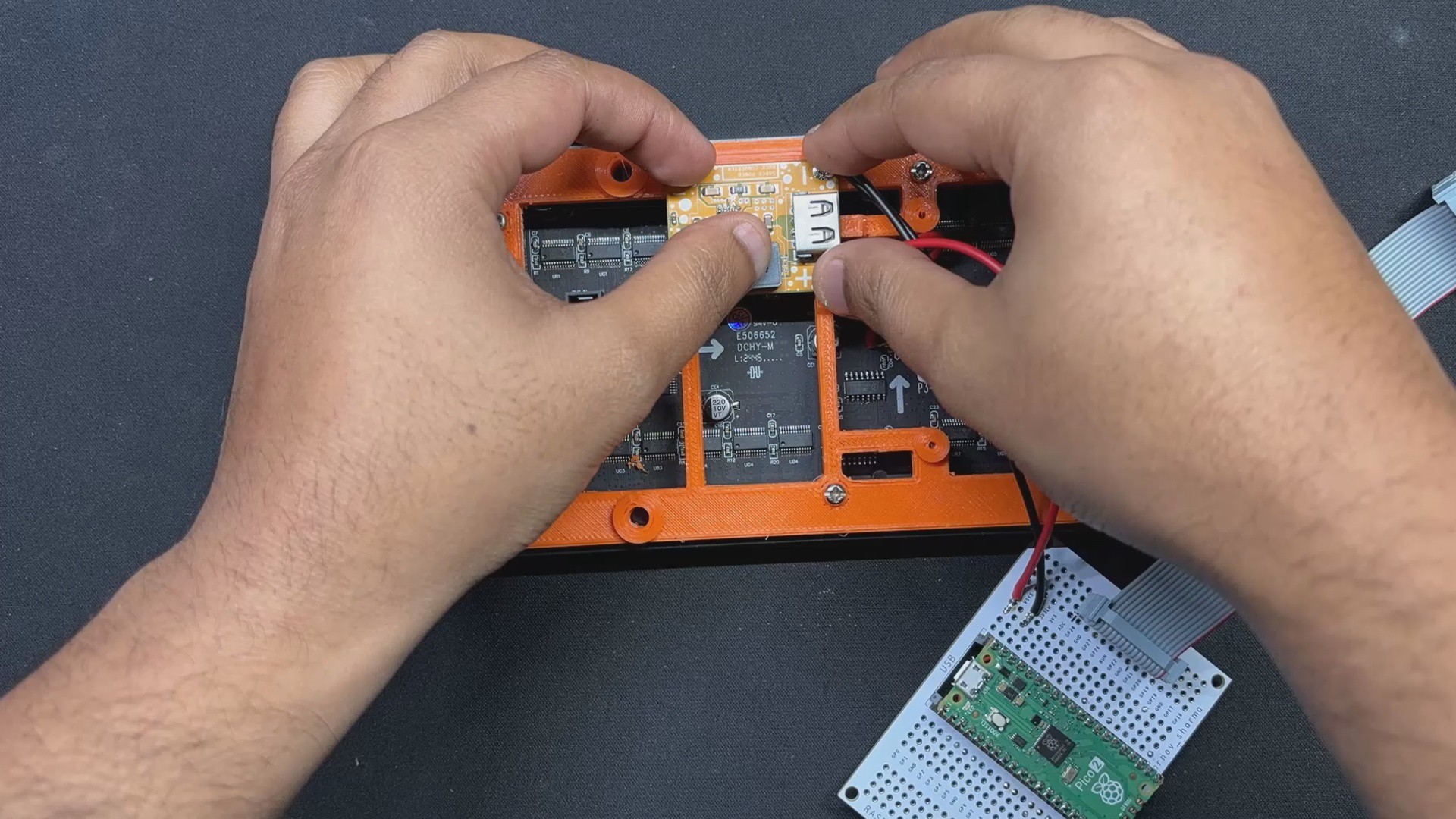
The Buck converter module's output side DC barrel jack is then disconnected, and it is then fastened to the mounting hole on the frame section.
Next, we connect the VCC and GND of the DC barrel jack to the Buck converter board's Vin and GND.
We attach the Buck converter board to the frame by positioning it there and then using hot glue to secure it in place.
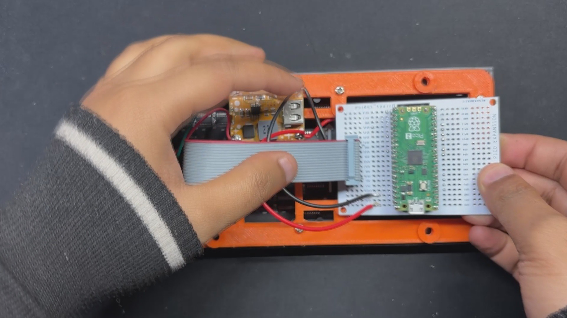
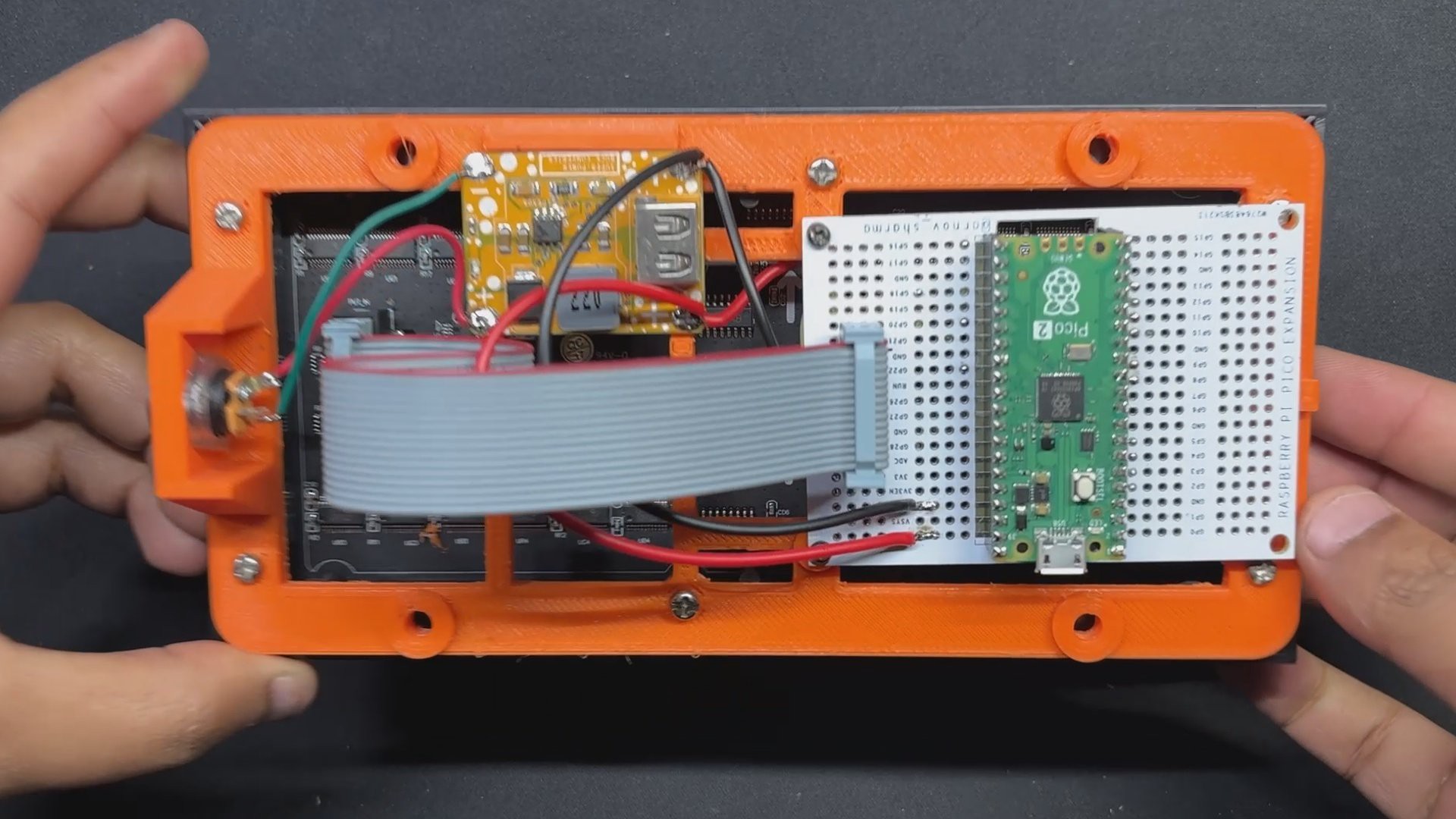
The CON16 Ribbon Cable connector, which was included with the matrix board, is then connected to the input connector of the matrix. The matrix and PICO are connected by this CON16 connector
Two M2 screws are then used to secure the PICO breakout board in place after it has been positioned over its location on the frame.
The assembly process is now complete.
6
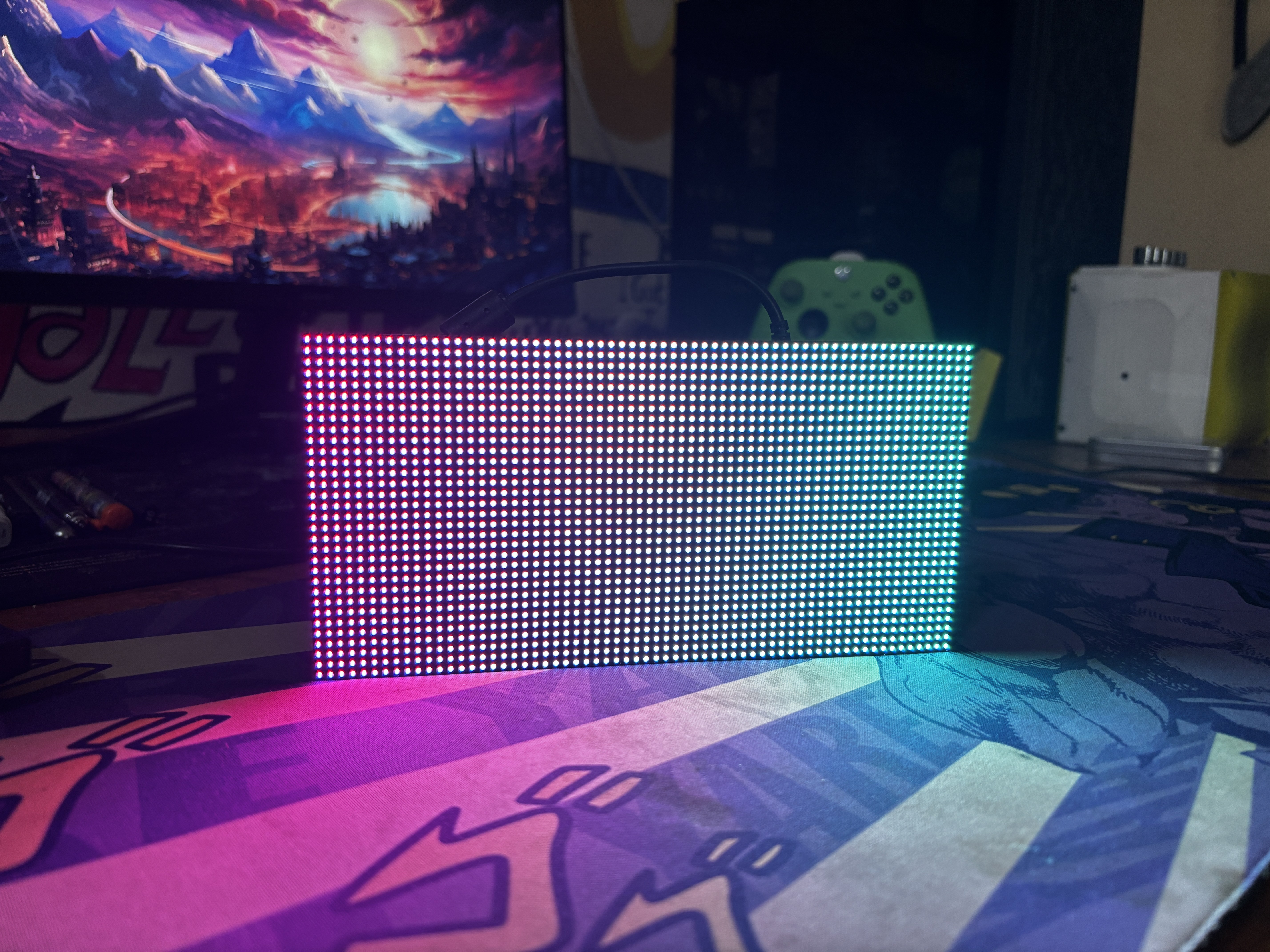
Test 01: Matrix Hello World
After the matrix setup is complete, we connect the PICO to our computer to upload code and plug the matrix in with a 12V adapter via the barrel DC socket to begin the test procedure.
We made this simple Hello World Sketch, which initializes the RGB matrix to display a variety of colorful animations, including gradients, diagonal lines, moving shapes, expanding circles, and scrolling text, to demonstrate the matrix's graphical capabilities.
#include<Adafruit_Protomatter.h>// Pin definitions#define R1 2#define G1 3#define B1 4#define R2 5#define G2 8#define B2 9#define A 10#define B 16#define C 18#define D 20#define CLK 11#define LAT 12#define OE 13#define WIDTH 64#define HEIGHT 32uint8_t rgbPins[] = { R1, G1, B1, R2, G2, B2 };
uint8_t addrPins[] = { A, B, C, D };
Adafruit_Protomatter matrix(WIDTH, HEIGHT, 1, rgbPins, 4, addrPins, CLK, LAT, OE, false);
bool grid[WIDTH][HEIGHT];
bool newGrid[WIDTH][HEIGHT];
voidsetup(){
matrix.begin();
randomSeed(analogRead(0));
// Initialize grid with random valuesfor(int x = 0; x < WIDTH; x++) {
for(int y = 0; y < HEIGHT; y++) {
grid[x][y] = random(2);
}
}
}
voidloop(){
matrix.fillScreen(0);
// Update grid based on Game of Life rulesfor(int x = 0; x < WIDTH; x++) {
for(int y = 0; y < HEIGHT; y++) {
int aliveNeighbors = countAliveNeighbors(x, y);
if(grid[x][y]) {
// Any live cell with two or three live neighbors survives.if(aliveNeighbors < 2 || aliveNeighbors > 3) {
newGrid[x][y] = false;
} else {
newGrid[x][y] = true;
}
} else {
// Any dead cell with three live neighbors becomes a live cell.if(aliveNeighbors == 3) {
newGrid[x][y] = true;
} else {
newGrid[x][y] = false;
}
}
if(newGrid[x][y]) {
matrix.drawPixel(x, y, matrix.color565(255, 255, 255)); // White color
}
}
}
// Copy newGrid to gridmemcpy(grid, newGrid, sizeof(grid));
matrix.show();
delay(100); // Adjust the delay for speed control// Check if the grid is stable or emptyif(isGridStableOrEmpty()) {
resetGrid();
}
}
intcountAliveNeighbors(int x, int y){
int aliveNeighbors = 0;
for(int dx = -1; dx <= 1; dx++) {
for(int dy = -1; dy <= 1; dy++) {
if(dx == 0 && dy == 0) continue;
int nx = (x + dx + WIDTH) % WIDTH;
int ny = (y + dy + HEIGHT) % HEIGHT;
if(grid[nx][ny]) {
aliveNeighbors++;
}
}
}
return aliveNeighbors;
}
boolisGridStableOrEmpty(){
for(int x = 0; x < WIDTH; x++) {
for(int y = 0; y < HEIGHT; y++) {
if(grid[x][y]) {
returnfalse;
}
}
}
returntrue;
}
voidresetGrid(){
for(int x = 0; x < WIDTH; x++) {
for(int y = 0; y < HEIGHT; y++) {
grid[x][y] = random(2);
}
}
}
Make sure to first install the Adafruit_Protomatter Library before using the sketch.
Next, in order to take this matrix setup to the next level, we created our own code that would run on our matrix panel by porting the Game of Life code that was obtained from an example sketch of the FastLED library.
The British mathematician John Horton Conway created the amazing cellular automaton known as the "Game of Life" in 1970. It is a zero-player game, which means that no additional input is needed; instead, the game's evolution is dictated by its beginning condition.
The game will start with a random configuration and restart with a new random configuration after it halts and yes this setup is Turing complete.
#include<Adafruit_Protomatter.h>// Pin definitions#define R1 2#define G1 3#define B1 4#define R2 5#define G2 8#define B2 9#define A 10#define B 16#define C 18#define D 20#define CLK 11#define LAT 12#define OE 13#define WIDTH 64#define HEIGHT 32uint8_t rgbPins[] = { R1, G1, B1, R2, G2, B2 };
uint8_t addrPins[] = { A, B, C, D };
Adafruit_Protomatter matrix(WIDTH, HEIGHT, 1, rgbPins, 4, addrPins, CLK, LAT, OE, false);
bool grid[WIDTH][HEIGHT];
bool newGrid[WIDTH][HEIGHT];
voidsetup(){
matrix.begin();
randomSeed(analogRead(0));
// Initialize grid with random valuesfor(int x = 0; x < WIDTH; x++) {
for(int y = 0; y < HEIGHT; y++) {
grid[x][y] = random(2);
}
}
}
voidloop(){
matrix.fillScreen(0);
// Update grid based on Game of Life rulesfor(int x = 0; x < WIDTH; x++) {
for(int y = 0; y < HEIGHT; y++) {
int aliveNeighbors = countAliveNeighbors(x, y);
if(grid[x][y]) {
// Any live cell with two or three live neighbors survives.if(aliveNeighbors < 2 || aliveNeighbors > 3) {
newGrid[x][y] = false;
} else {
newGrid[x][y] = true;
}
} else {
// Any dead cell with three live neighbors becomes a live cell.if(aliveNeighbors == 3) {
newGrid[x][y] = true;
} else {
newGrid[x][y] = false;
}
}
if(newGrid[x][y]) {
matrix.drawPixel(x, y, matrix.color565(255, 255, 255)); // White color
}
}
}
// Copy newGrid to gridmemcpy(grid, newGrid, sizeof(grid));
matrix.show();
delay(100); // Adjust the delay for speed control// Check if the grid is stable or emptyif(isGridStableOrEmpty()) {
resetGrid();
}
}
intcountAliveNeighbors(int x, int y){
int aliveNeighbors = 0;
for(int dx = -1; dx <= 1; dx++) {
for(int dy = -1; dy <= 1; dy++) {
if(dx == 0 && dy == 0) continue;
int nx = (x + dx + WIDTH) % WIDTH;
int ny = (y + dy + HEIGHT) % HEIGHT;
if(grid[nx][ny]) {
aliveNeighbors++;
}
}
}
return aliveNeighbors;
}
boolisGridStableOrEmpty(){
for(int x = 0; x < WIDTH; x++) {
for(int y = 0; y < HEIGHT; y++) {
if(grid[x][y]) {
returnfalse;
}
}
}
returntrue;
}
voidresetGrid(){
for(int x = 0; x < WIDTH; x++) {
for(int y = 0; y < HEIGHT; y++) {
grid[x][y] = random(2);
}
}
}
8
Conclusion, and what's next?
This project ended with a functional matrix setup that is simple to work with due to the PICO 2 implementation and the addition of a DC buck converter circuit on the rear that enables the user to power it from a 12V source, so resolving the power source issue entirely.
We created this configuration in order to utilize the matrix in a future project that will be a portable gaming device that runs Snake Game.
We have currently prepared a demo sketch that initializes a snake in the center of the RGB matrix and causes it to travel. The snake's direction of movement changes randomly at different points in time, looping around the corners of the screen.
This project turned out well overall, and I'll be returning with the Snake gaming Console, which will dive deeply into the construction of the Snake gaming device.
 Arnov Sharma


Discussions
Become a Hackaday.io Member
Create an account to leave a comment. Already have an account? Log In.