 Arnov Sharma
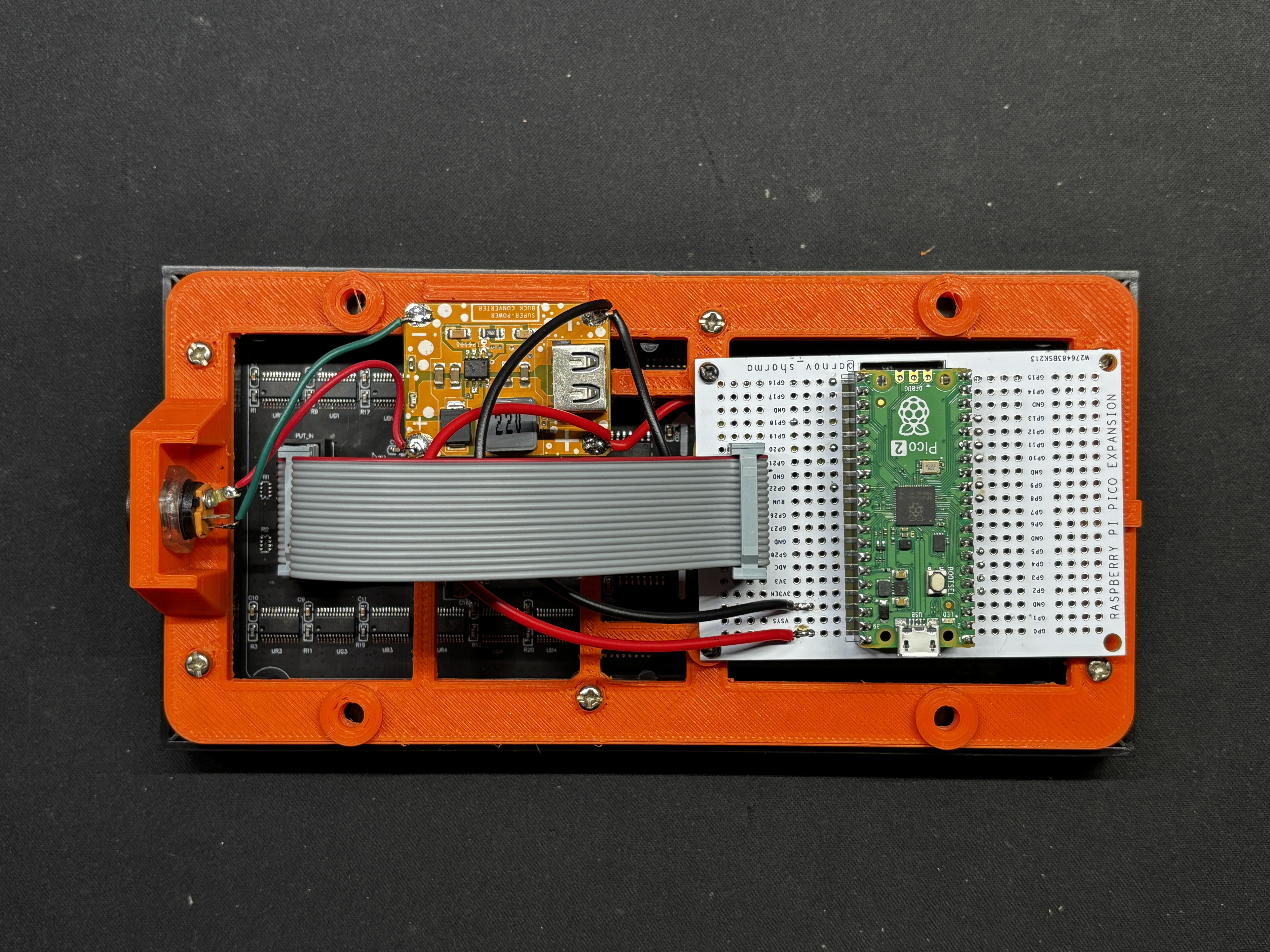
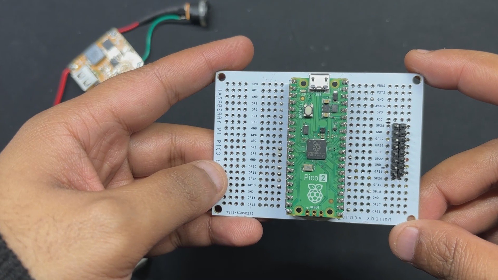
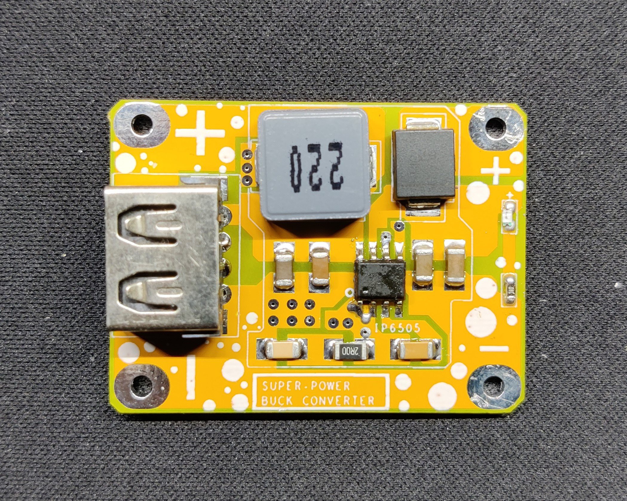
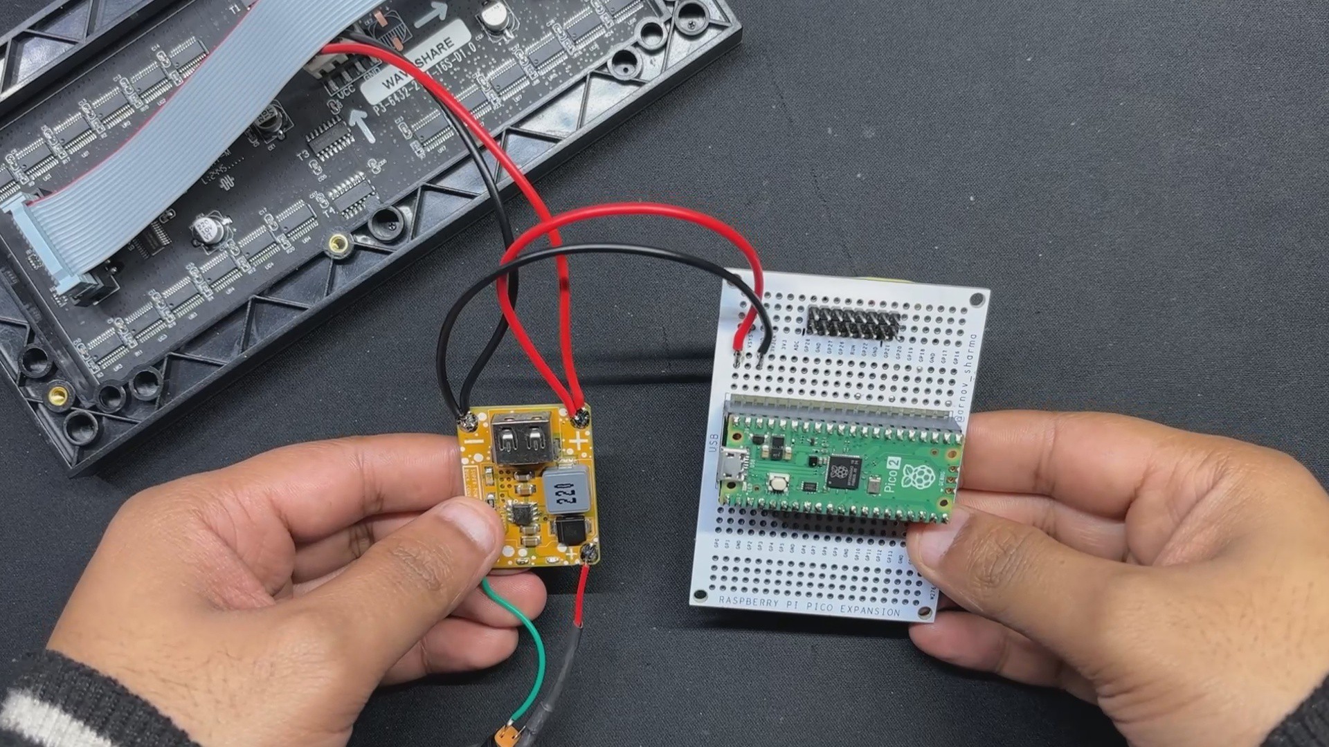
We included a DC-DC Buck converter board that we had previously designed to address the issue of the Matrix panels' high power consumption and the PICO's inability to power the entire panel via its USB Out pin.
The 12V from the adaptor is stepped down into a steady 5V/3A using the Buck converter board, which is sufficient to power the PICO and drive the matrix panel.
We created a frame-like part that is fastened to the rear of the matrix panel to keep everything orderly. It secures the PICO 2 circuit, the Buck controller board, and the DC Barrel jack.
This article covers the entire Matrix Setup build guide, including the test code and other details.
64x32 RGB Matrix
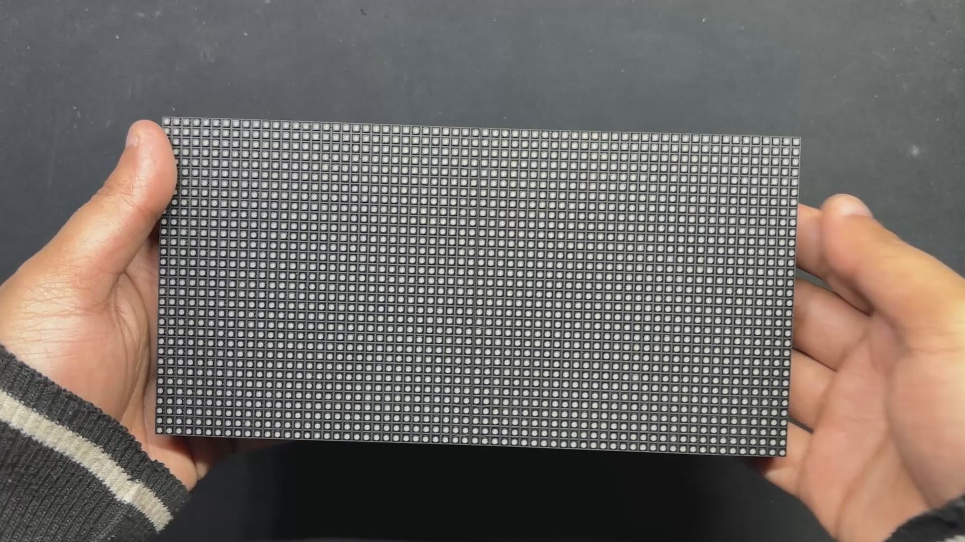
In this project, we are utilizing the 64x32 RGB matrix panel, which consists of 2048 RGB LEDs arranged in a 64 by 32 grid, which produces vibrant text, images, and animations.
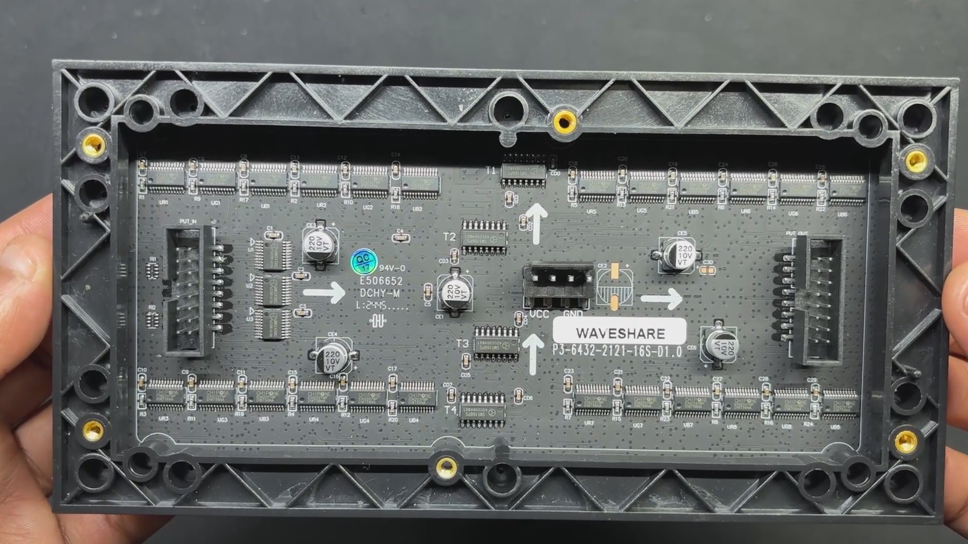
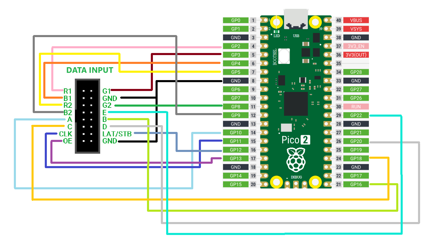
This panel is controlled using a HUB75 interface, which relies on multiple control pins, including RGB pins, address pins, a clock pin, a data latch, and an output enable pin.
The HUB75 connection enables the row-column scanning method by shifting a row of pixel data into a shift register, then using a demultiplexer to select which rows to display. The HUB75 connector includes RGB channels, addressing pins (A, B, C, D), a clock signal (CLK), a latch signal (LAT), and an output enable (OE) pin.
This interface allows precise control over the LED matrix, enabling smooth and bright displays ideal for text, images, and animations.
While it might appear complex to set up, this method ensures high-intensity displays and smooth, seamless graphics transitions.
Using a 5V power source, we can drive this display, but there's a catch. The current draw can vary significantly depending on the number of LEDs lit and their brightness levels. A fully lit panel can draw substantial current, so a power supply capable of providing at least 4-5 Amps is recommended.
Additionally, by utilizing the included IN and OUT connectors, we can connect multiple panels in pairs and form a chain. One of the challenges of connecting numerous panels is ensuring that the control solution (PICO 2) we are employing can handle the extra data load or two or more displays.
With the PICO 2, we are currently using a single panel that can power two or more displays without causing any issues.
Waveshare made this matrix, and the wiki link below has more detailed information on the Matrix board:
https://www.waveshare.com/wiki/RGB-Matrix-P3-64x32
PCBWAY GIFTSHOP
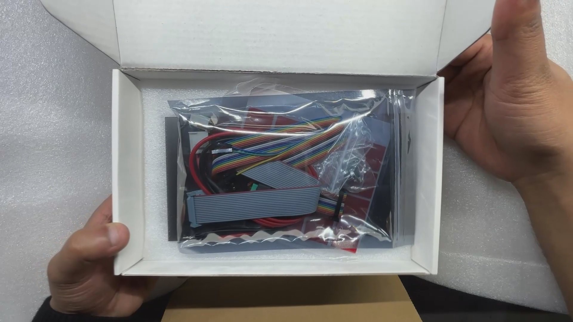

As for sourcing this matrix panel, we got it from the PCBWAY GIFTSHOP.
PCBWAY gift shop is an online marketplace where you can get a variety of electronics modules and boards for their genuine price, or you could use the PCBWAY currency, which is called beans.
You get beans after ordering something from PCBWAY as reward points, or you can also get them by posting any project in the PCBWAY community.
You guys can check out PCBWAY if you want great PCB service at an affordable rate.
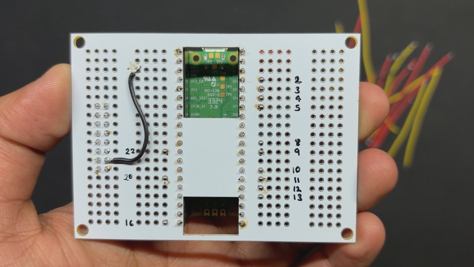
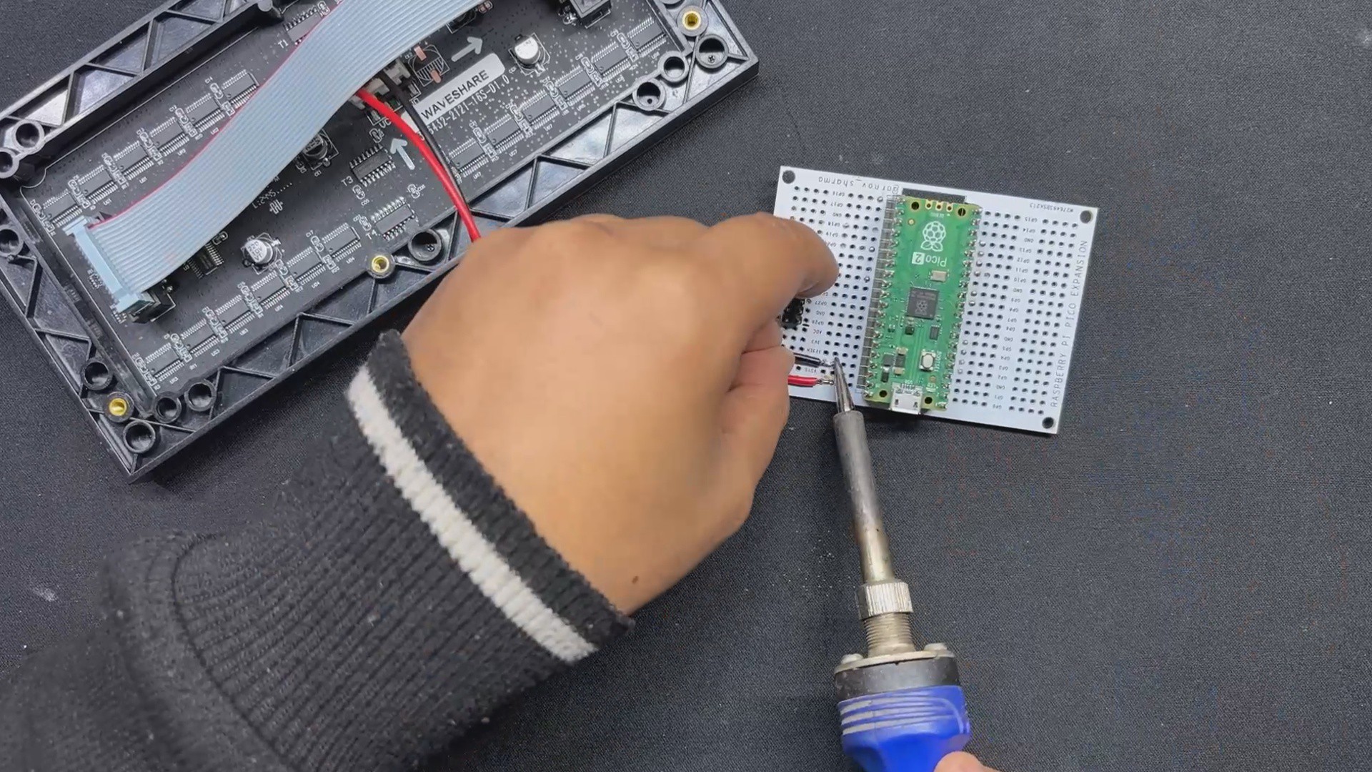
PICO BREAKOUT BOARD
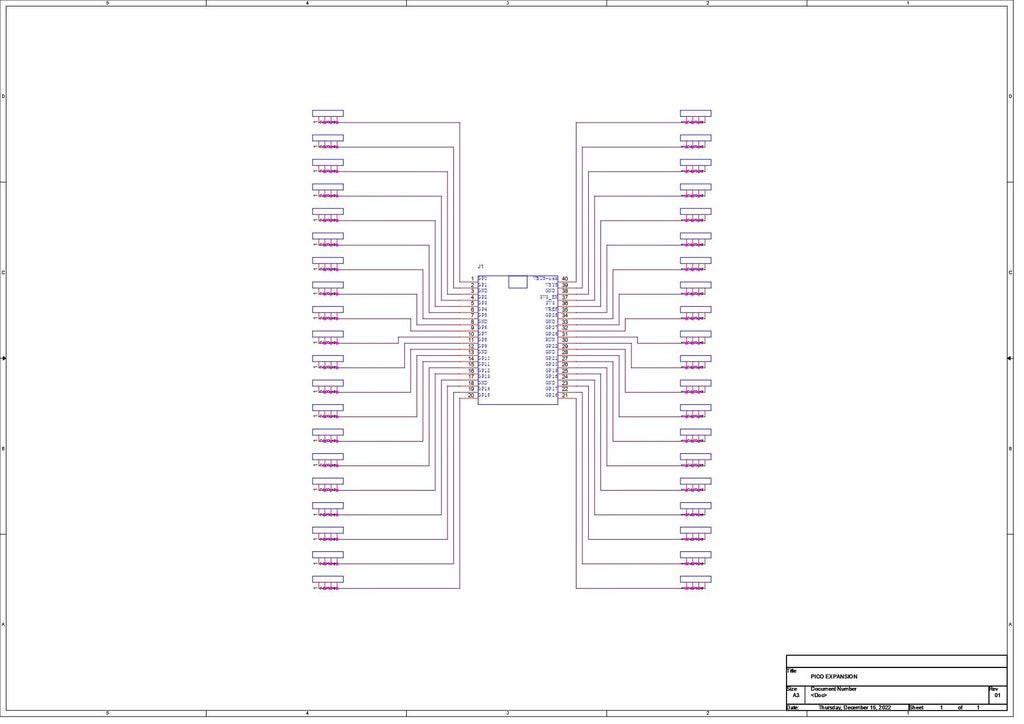
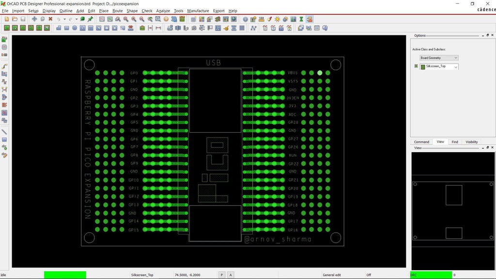
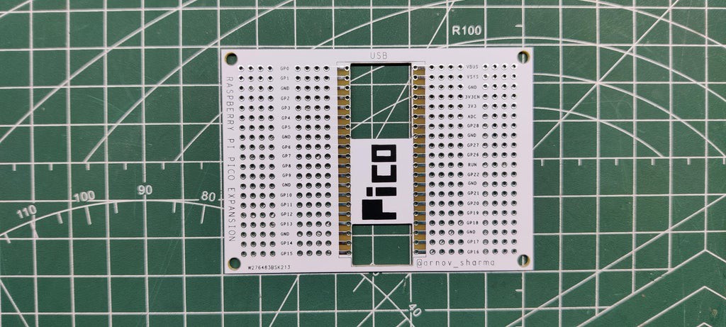
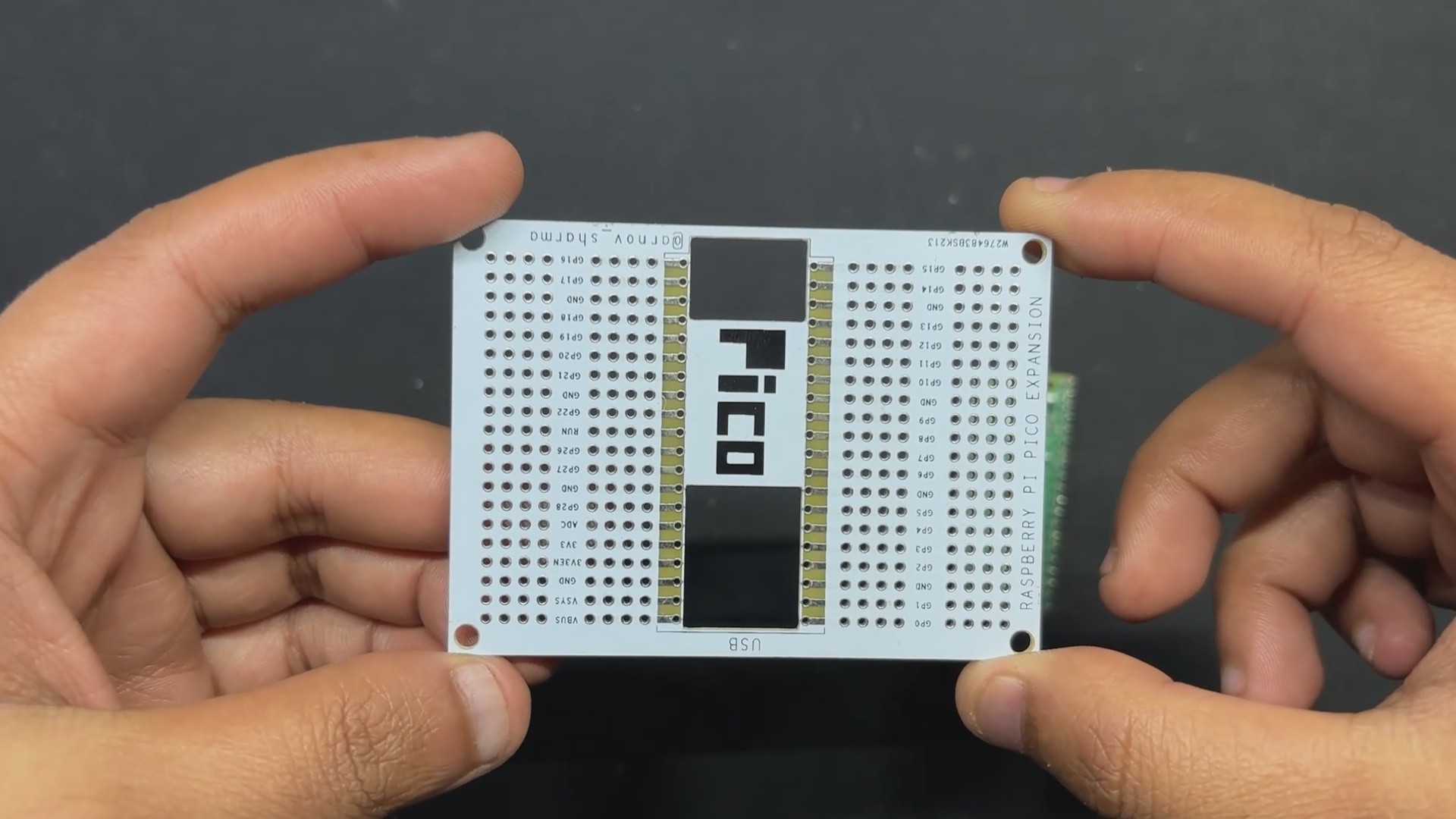
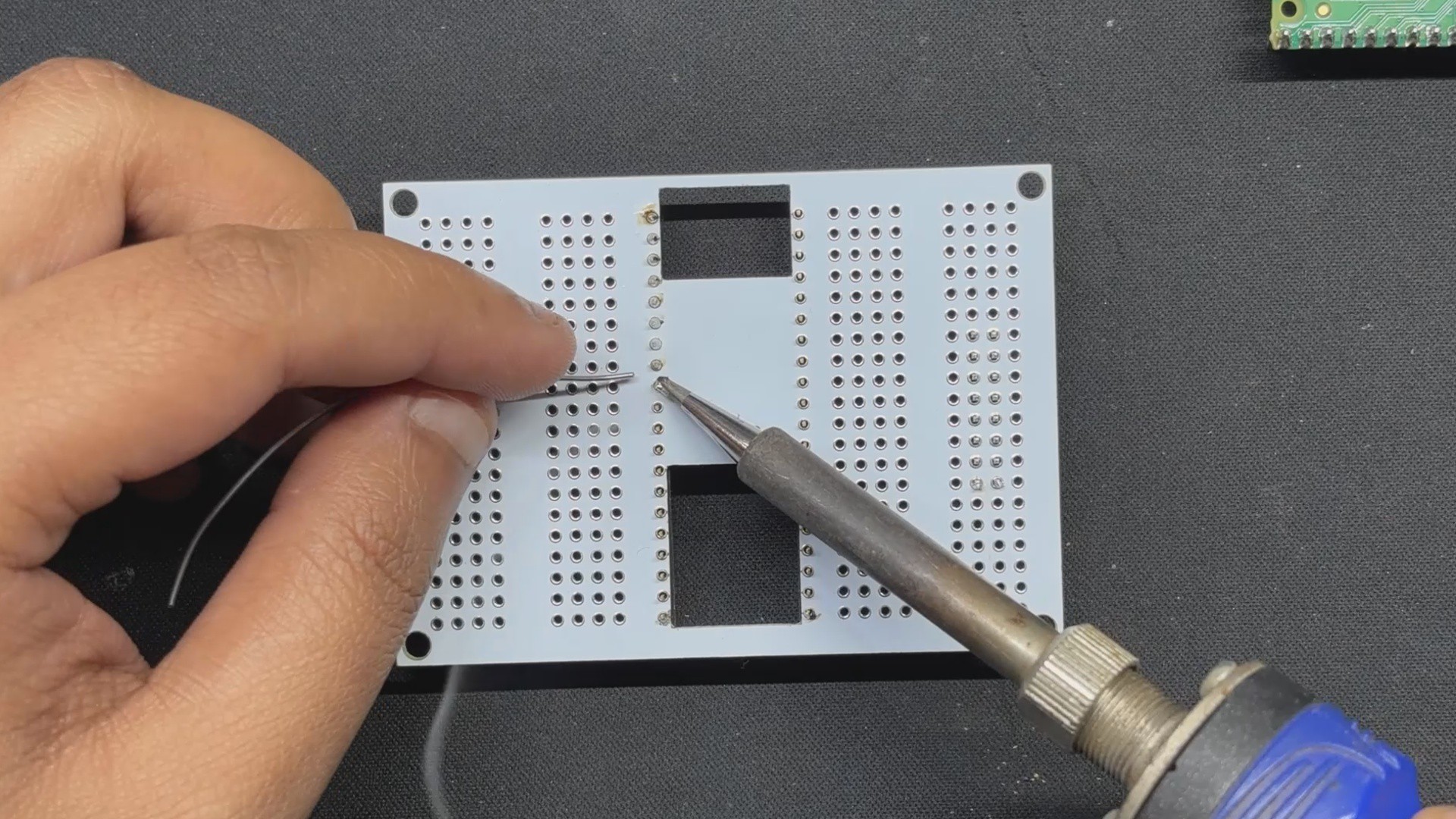
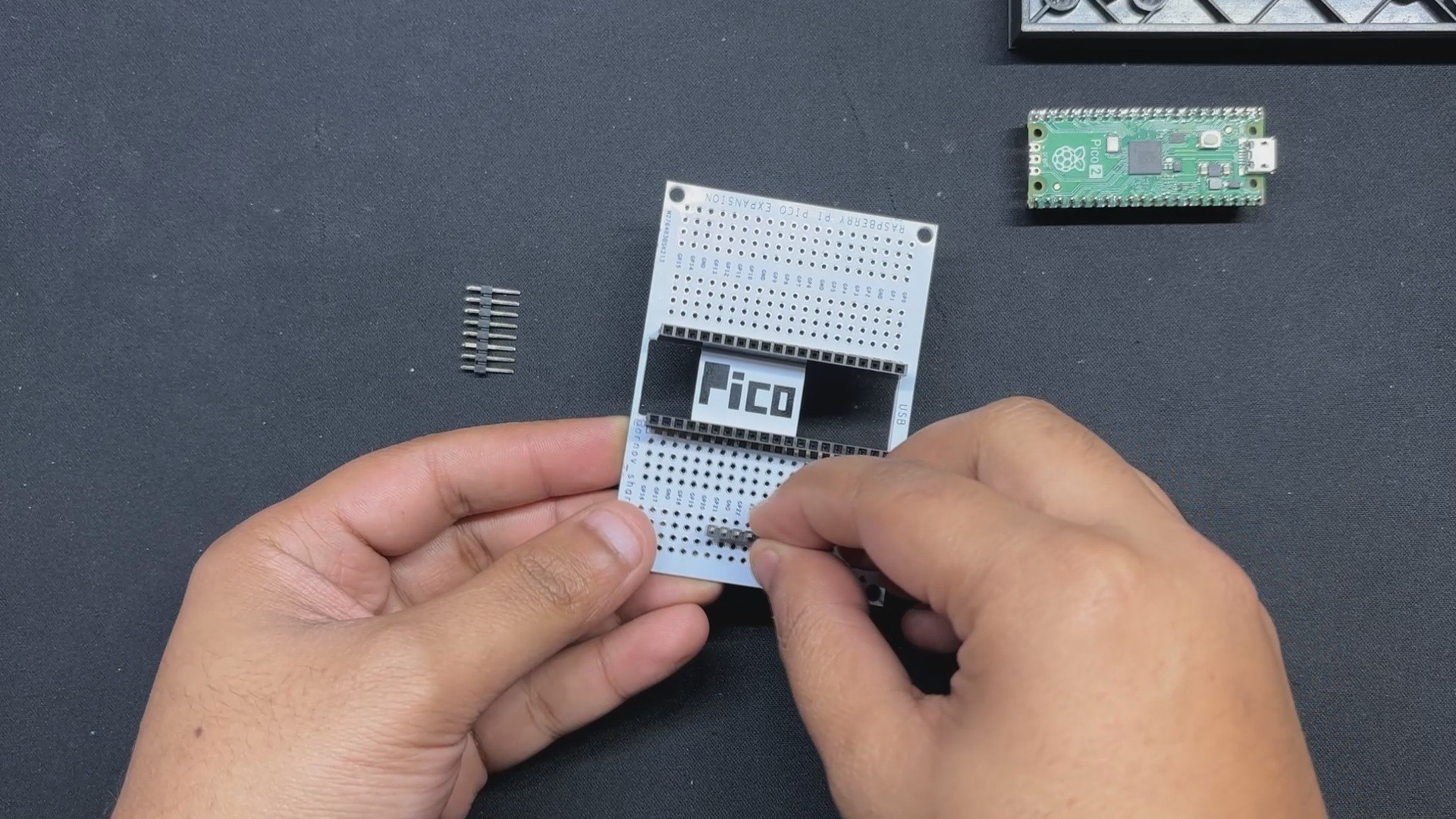
We utilized one of our previously constructed PICO expansion boards, a straightforward circuit that resembles a prototype board with a PICO footprint in the middle, to set up the PICO 2. Each Pico pin is connected to a CON4 header pin footprint, which is laid out on the left and right sides of the board. Each pin is labeled, making it easier to work with PICO.
https://www.hackster.io/Arnov_Sharma_makes/raspberry-pi-pico-as-hid-mouse-370827
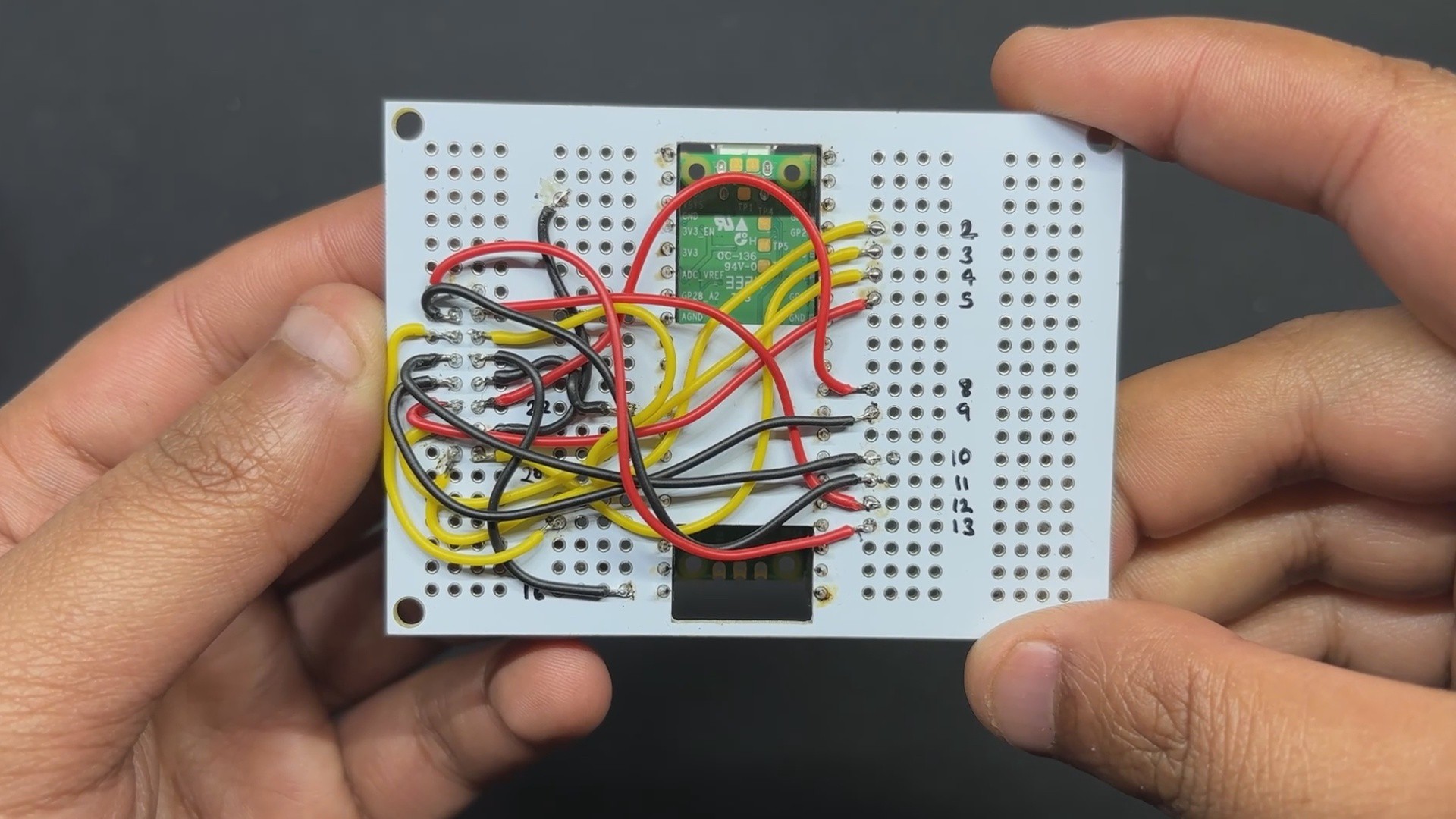
In order to connect electric components and pair them with the PICO pins, we also added a few unconnected pins to the left and right sides of the board. In order to connect display I/O pins with the PICO GPIO pins, we will be adding a CON16 pin to these unconnected pins.

 IoT-devices, LLC
 Jared Sanson
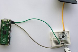

 Clovis Fritzen