Daniel Knezevic
-
v2 is here
10/21/2025 at 09:22 • 0 comments![]()
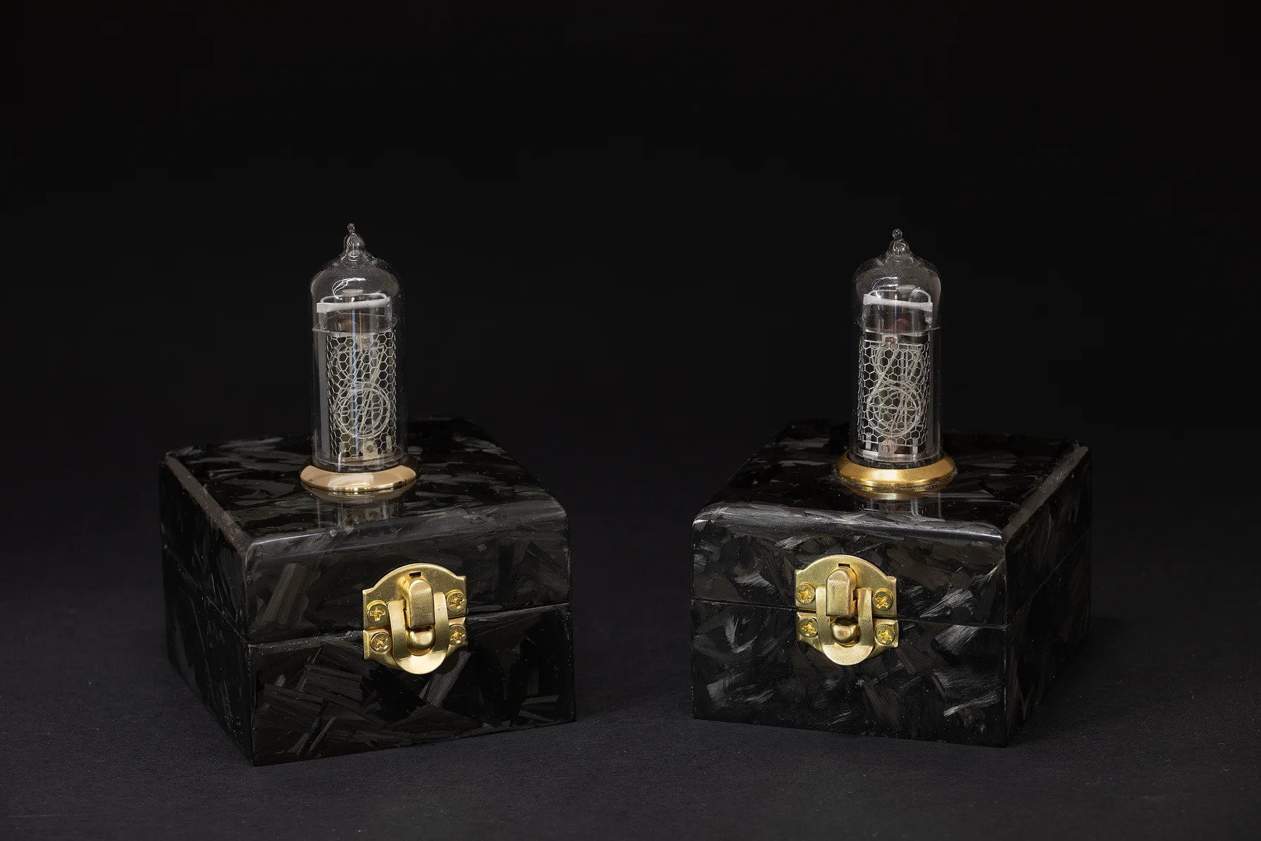
Although these two clocks look identical on the outside, everything under the hood has been redesigned and improved - from the hardware to the firmware. Only the case design stayed the same, but its finishing has improved too.
Version 2.0.0 comes with the following set of changes:
- Improved performance and reliability.
- Removed manual daylight saving time handling from the GUI.
- Easier time zone selection based on city/country.
- Added option for choosing 12 hour time format.
- Added support for various Wi-Fi encryption types.
- Added RGB fade effect to LED at startup.
- ESP8266 has been swapped with the ESP32-WROOM-32 module.
![]()
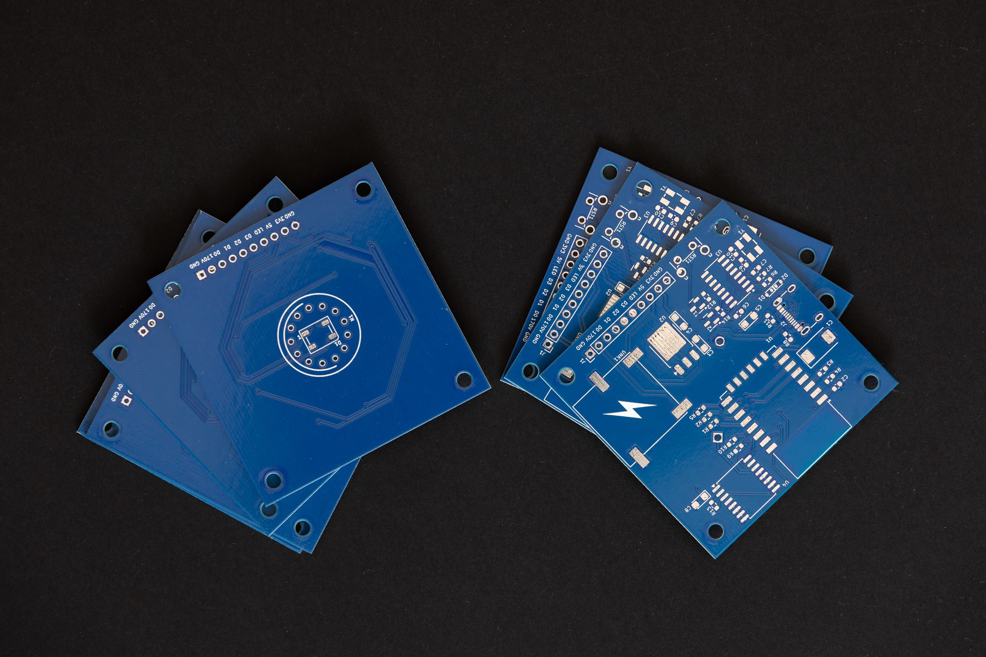
A big thank you to PCBWay for sponsoring this project and providing PCBs for the new version of single digit nixie clock.
As I described in the documentation, the possibility of switching to ESP32 came to realization. I made the switch for a couple of reasons:
- It is a good opportunity to get familiar with ESP-IDF
- It has Bluetooth that can be used for new features
esides this, I had a major problem with the previous implementation of the nixie clock. The ESP8266/Arduino combo had an issue with random restarts originating from third party libraries. To be more precise ESPAsyncWebServer. System restarts occurred when certain functions or loops became unresponsive during periods of slow Wi‑Fi connectivity, causing the watchdog timer (WDT) to trigger. To solve this problem I decided to make radical changes. Instead of finding a better Arduino library for the web server I decided to get rid of the Arduino framework with 3rd party libraries and use the SDK provided by Espressif. There was an option to use the ESP8266 RTOS SDK, but I opted to switch to ESP32 and use ESP-IDF instead. ESP-IDF is more future proof, so there is no point in using something outdated.
The SDK contains everything I need for this project: HTTP server, mDNS server, SNTP support, RMT for RGB LED, … it made porting the old code to ESP32 easier.
As a result, the firmware became more robust and stable. The above-mentioned crashes disappeared. ESP-IDF’s implementation of standard C time functions, which are POSIX-compatible, simplifies time and time zone management. The system automatically calculates local time based on the user-configured time zone, including daylight saving adjustments, so there is no need for manual handling on the front-end.
Using FreeRTOS tasks for handling the LED and Nixie tube simplified the code and improved readability.Hardware changes
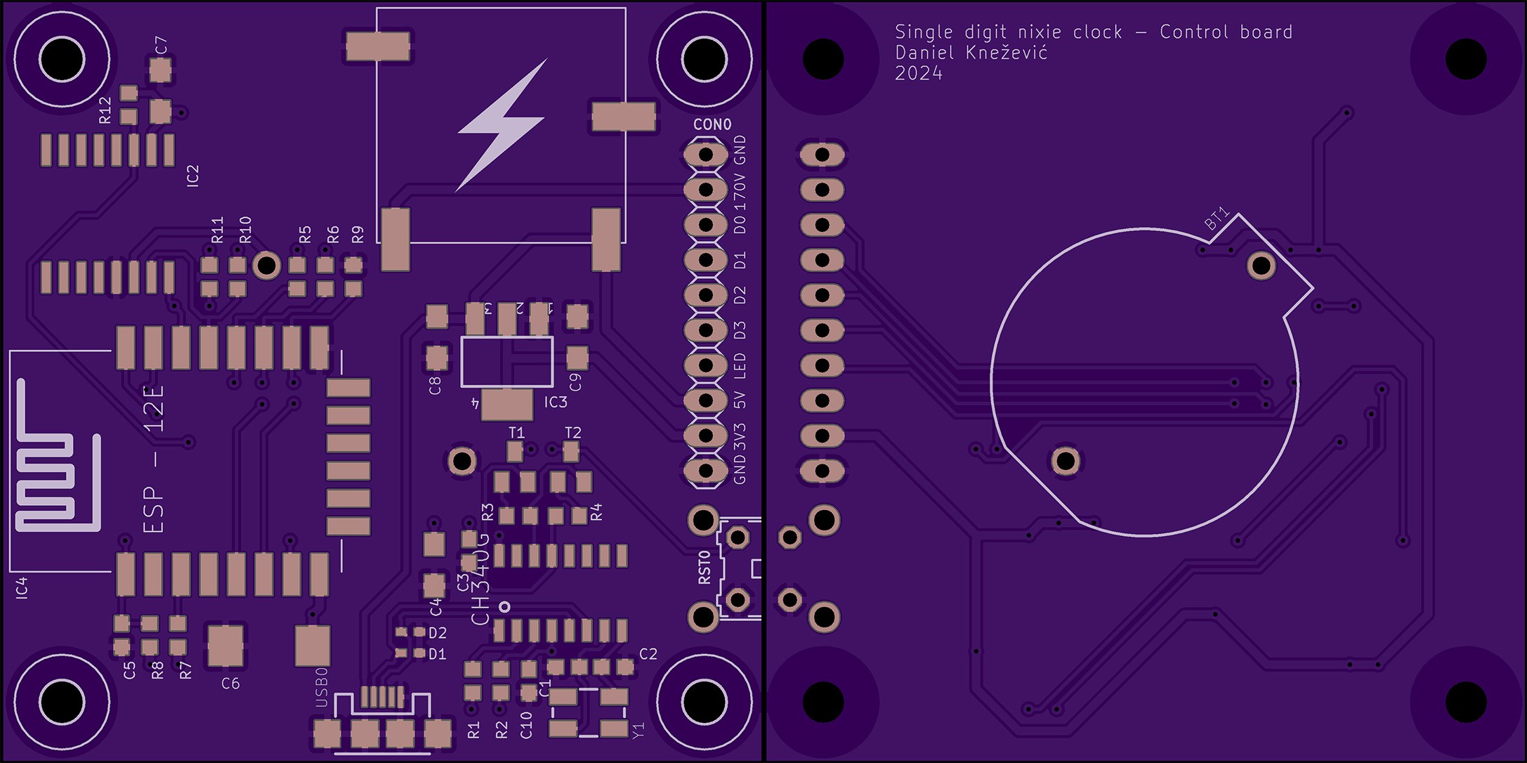
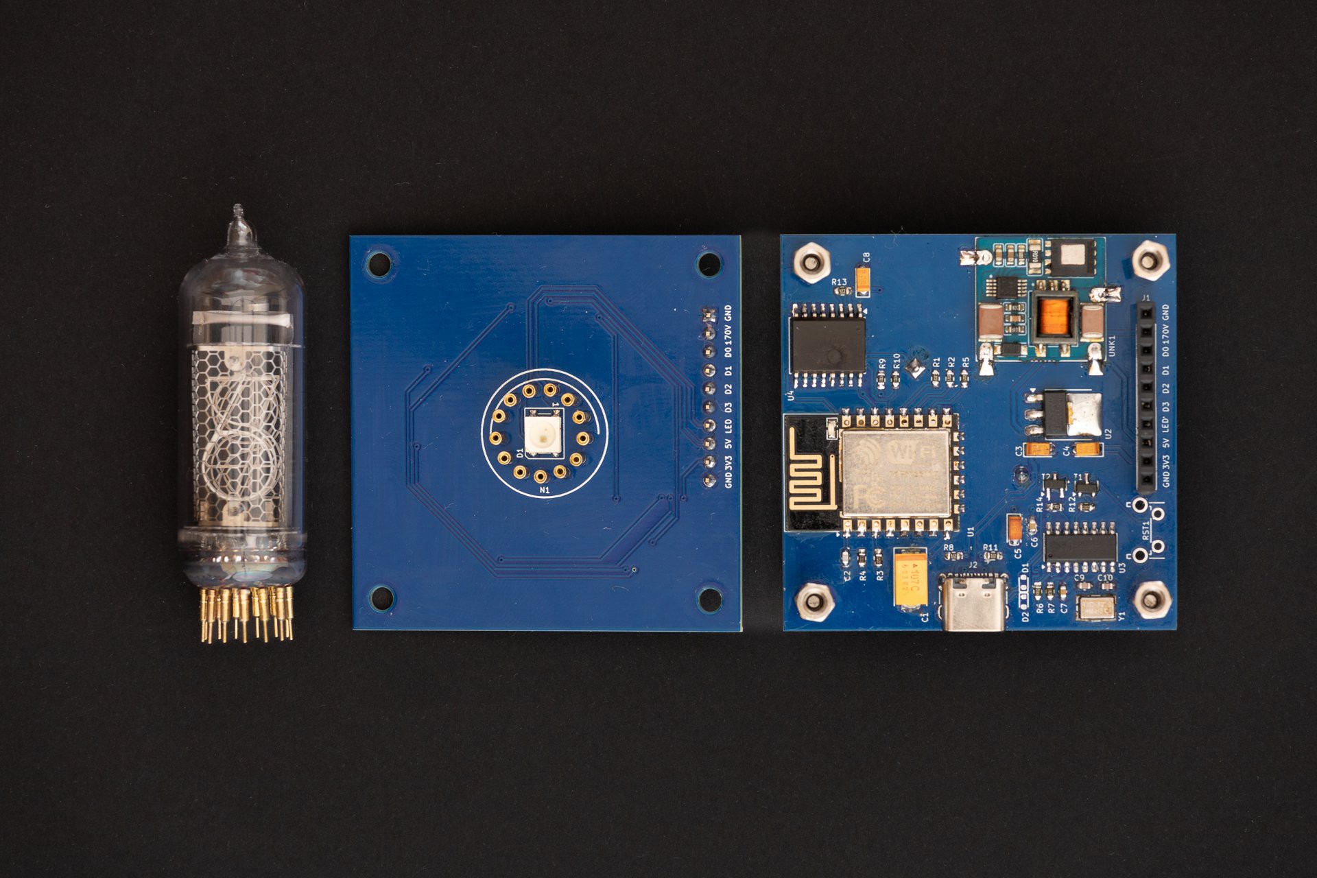
The control board has been slightly redesigned to use the ESP32-WROOM-32 module. While ESP32 has better support for time keeping, compared to ESP8266, I still left the RTC and external battery on the board. External RTC can be used for storing the current time for cases when the device is not connected to the internet.
![]()
Issues & Fixes - Control board
Control board had an issue with the auto-programming circuit. While the serial monitor worked fine, flashing firmware with `esptool.py` always failed with the following error:
A fatal error occurred: Failed to connect to ESP32: No serial data received.
As a quick fix, I manually entered programming mode by shorting the IO0 pin to ground while esptool.py displayed the Connecting........ message.
It is a know issue based on online articles/forums manifesting as a timing issue. Entering programming mode requires a specific sequence of EN and IO0 signal transitions. A common fix is adding a capacitor (100 nF – 10 µF) between EN and GND. However, this did not resolve my issue.
To debug further, I used a small Python script to toggle the RTS and DTR pins on the CH340 while monitoring EN and IO0 signals at ESP32 with a multimeter.
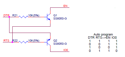
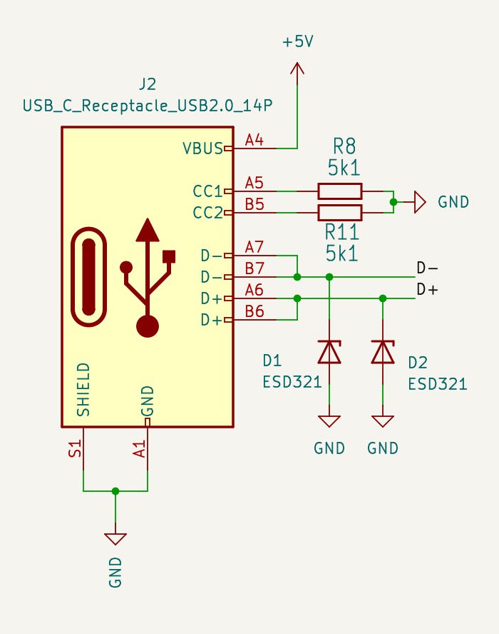
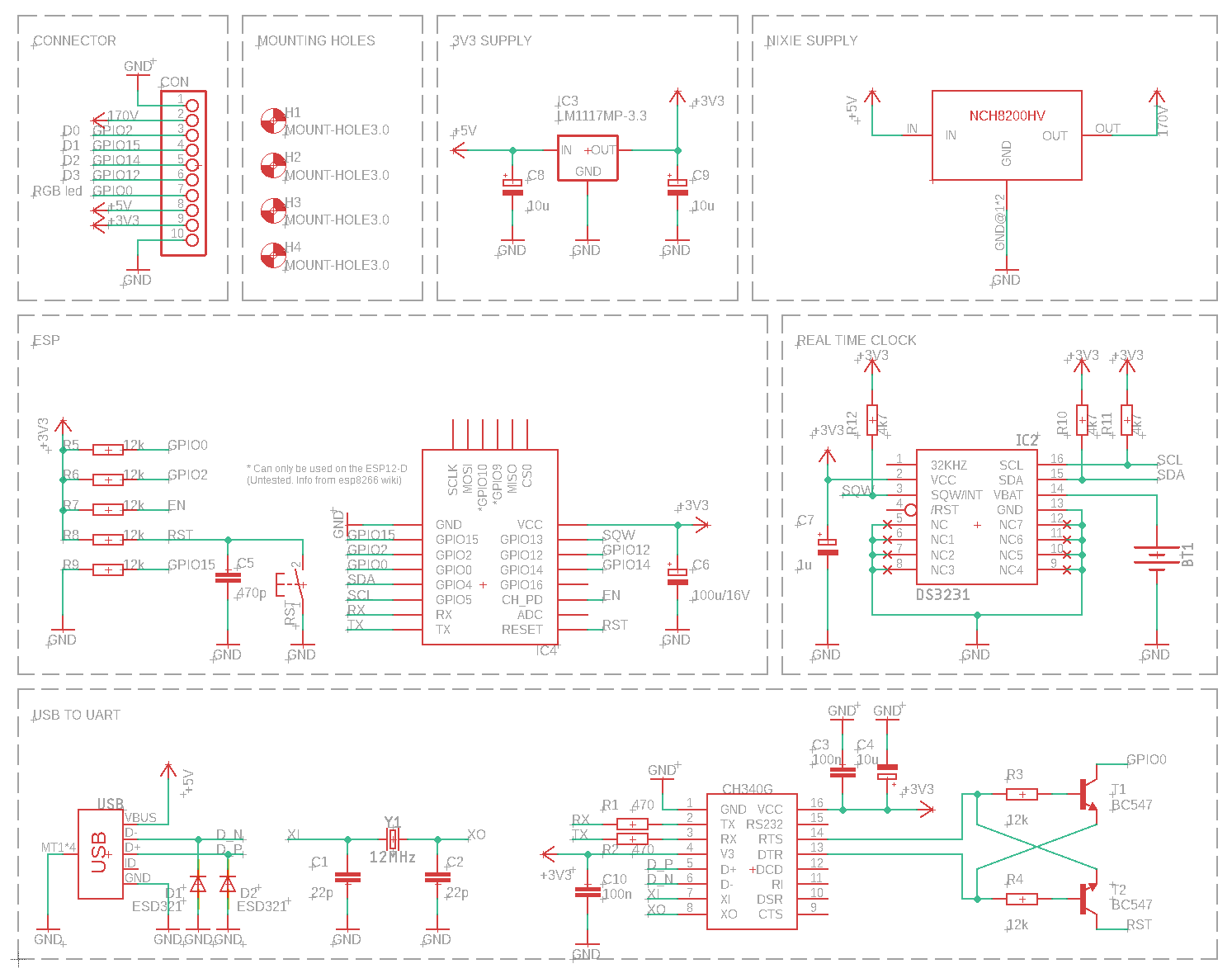
Here is the auto-programming circuit with its truth table:
![]()
According to the truth table, when DTR is low and RTS is high, the ESP32’s EN and IO0 pins should be inverted (EN = high, IO0 = low). On my setup the actual results were not matching expected values. I looks like pull up resistors were missing on these pins. Adding them fixed the programming issue. As a good measure I've added a 100nF ceramic capacitor between EN and GND.
Here is the Python script:
#!/usr/bin/python3
import serial
import time
import sys

if len(sys.argv) != 2:
    print(f"Usage: {sys.argv[0]} <serial_port>")
    sys.exit(1)

port = sys.argv[1]

try:
    ser = serial.Serial(port, baudrate=9600)
    print(f"Toggling RTS/DTR on {port}. Press Ctrl+C to stop.")

    while True:
        ser.rts = True
        ser.dtr = False
        print("RTS: HIGH, DTR: LOW")
        time.sleep(10)
        ser.rts = False
        ser.dtr = True
        print("RTS: LOW, DTR: HIGH")
        time.sleep(10)

except KeyboardInterrupt:
    print("\nExiting...")

finally:
    ser.close()
Issues & Fixes - Control board
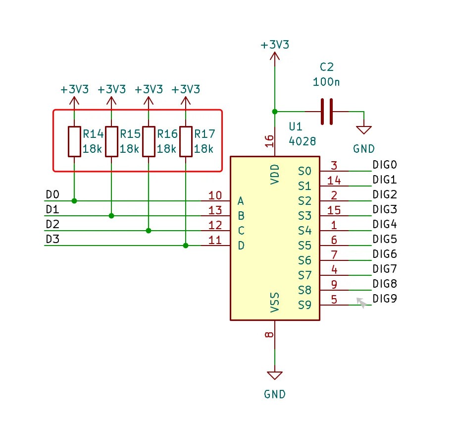
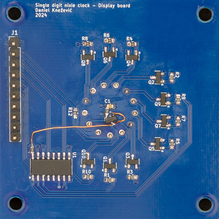
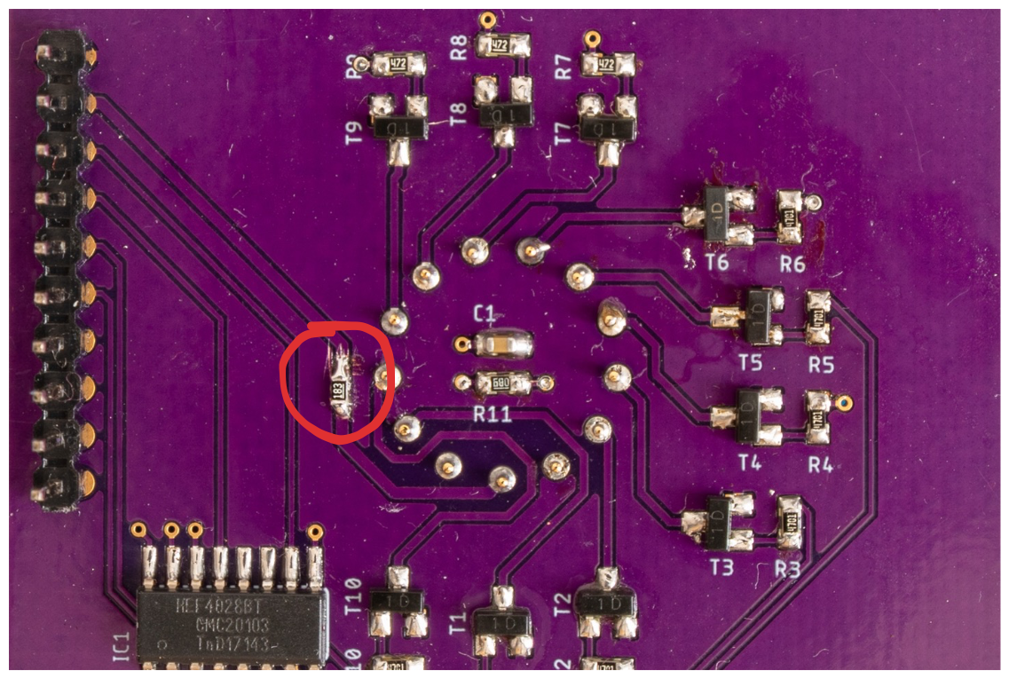
During boot, the display board showed a glowing “1” digit, even when no digit should be active. This was caused by floating input pins on the CD4028 BCD-to-decimal decoder.
To fix the issue, I added pull-up resistors to the CD4028 input pins so that the default input state is `0xF`, which results in all outputs being low.![]()
Case
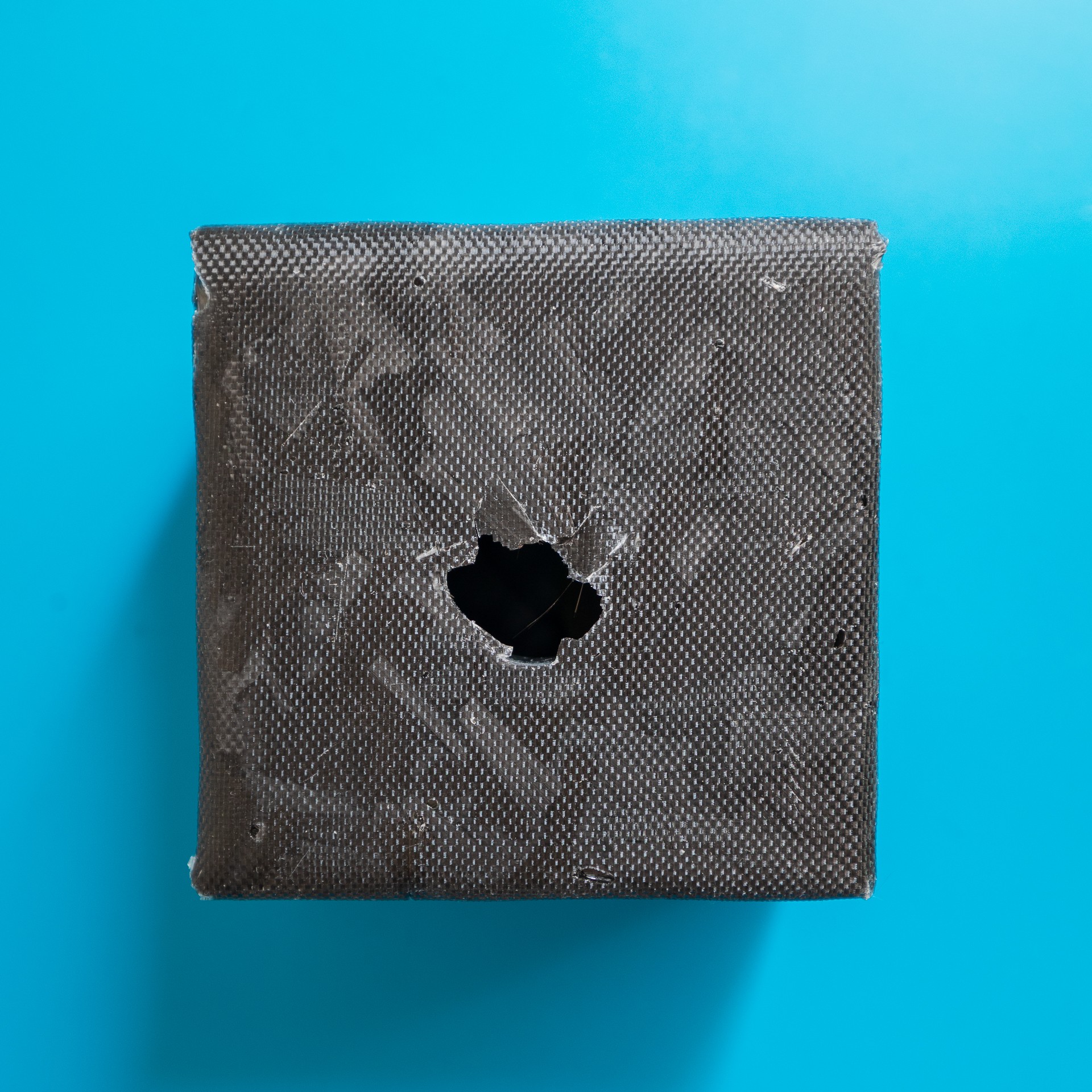
The case design remained unchanged, but the carbon flake finish has been improved a bit. Since the 3D-printed box was light grey, I needed to ensure every surface was fully covered with carbon. The good thing is, it is easy to fix gaps by adding a new layer of carbon and epoxy.
-
Enclosure design - Part 2
04/27/2025 at 18:14 • 0 commentsThe 3D printed case was just a path finder, to get a rough feeling about the shape and size. Originally, I planned to make the clock’s case out of wood (oak or walnut) and decorate it with brass bits and pieces to resemble a jewellery box. Then, I realised that almost all nixie clocks are boxed either in a wooden or acrylic box.
Since the title states this project is an “artistic clock” I wanted to make something to stand out from others besides having only one nixie tube.
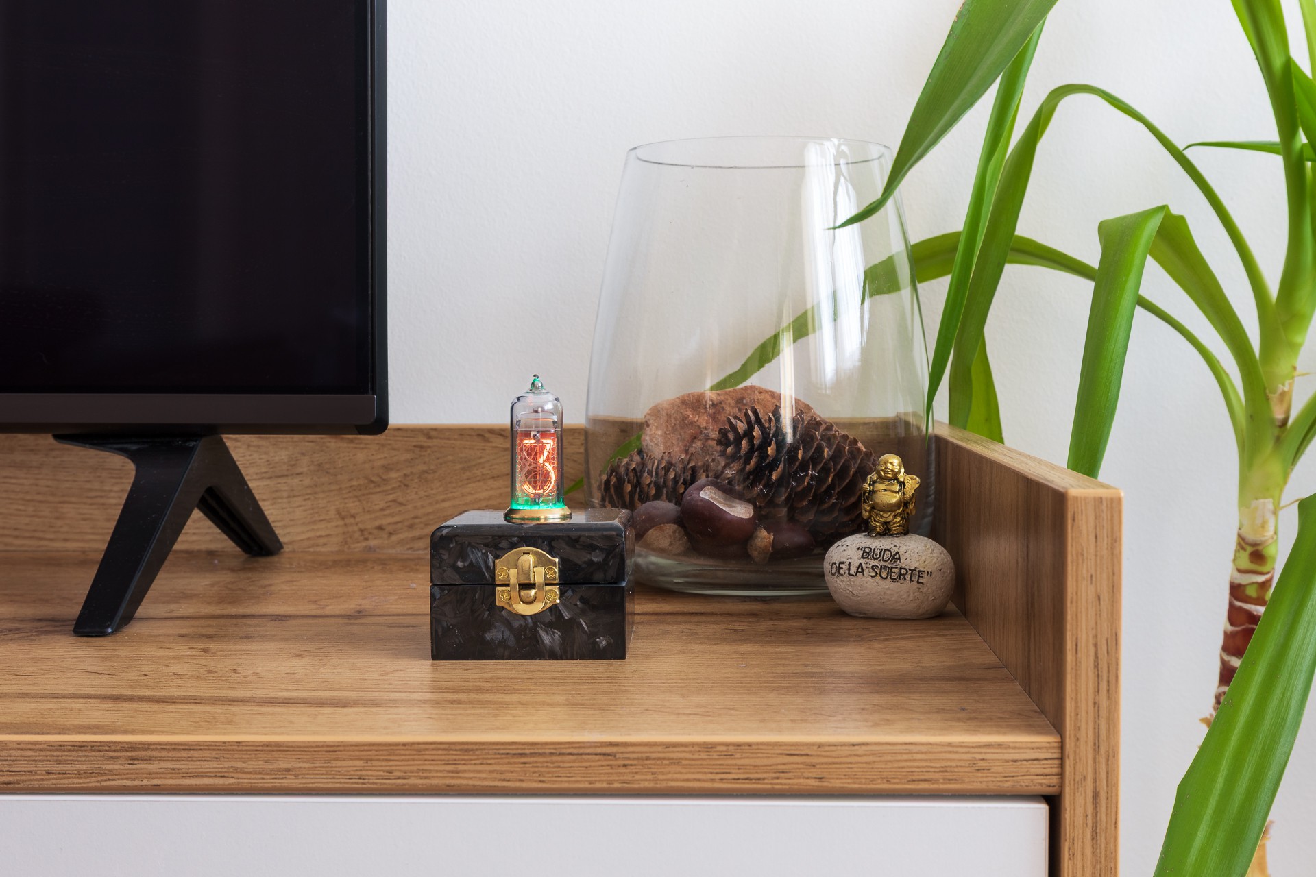
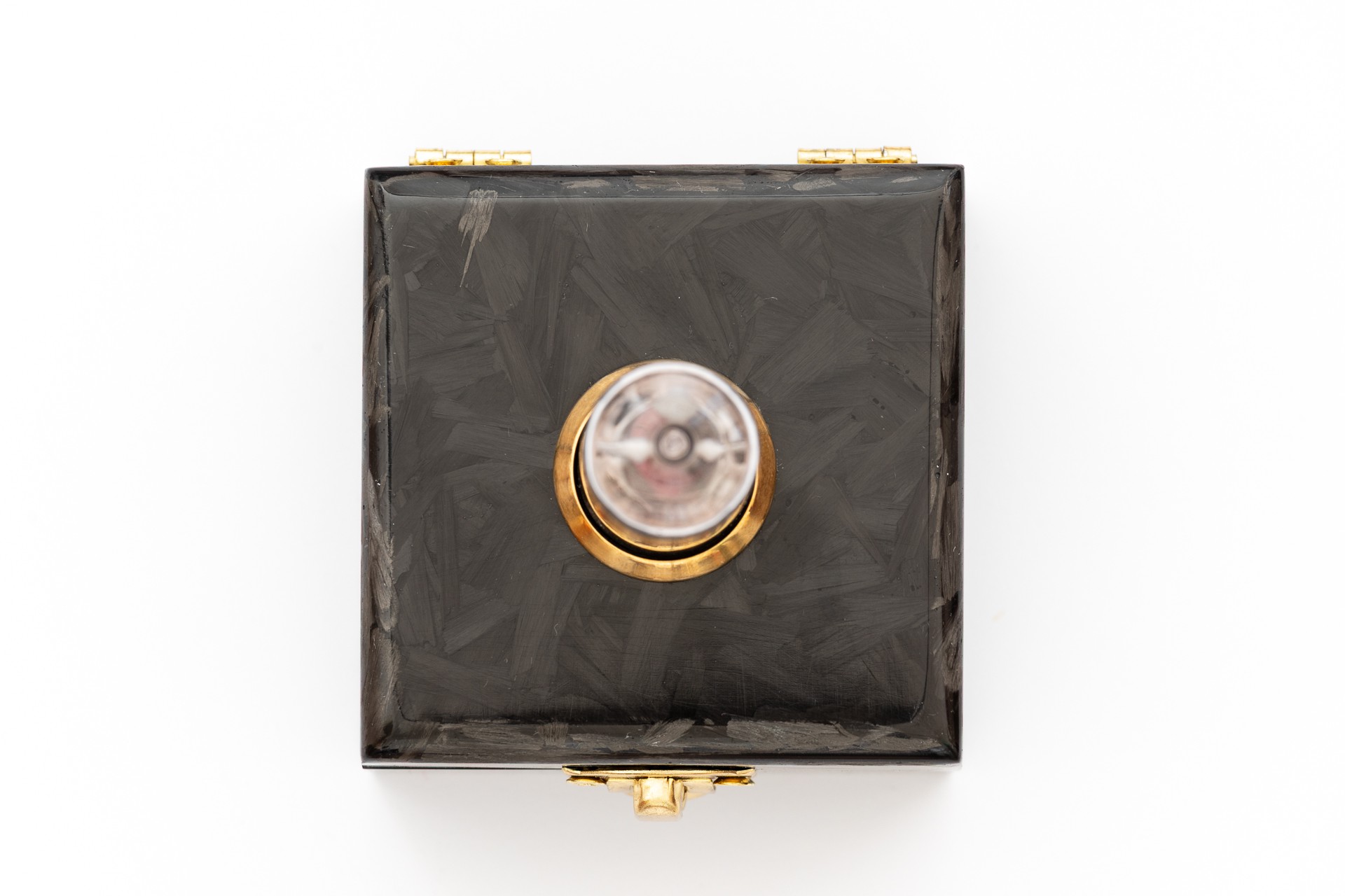
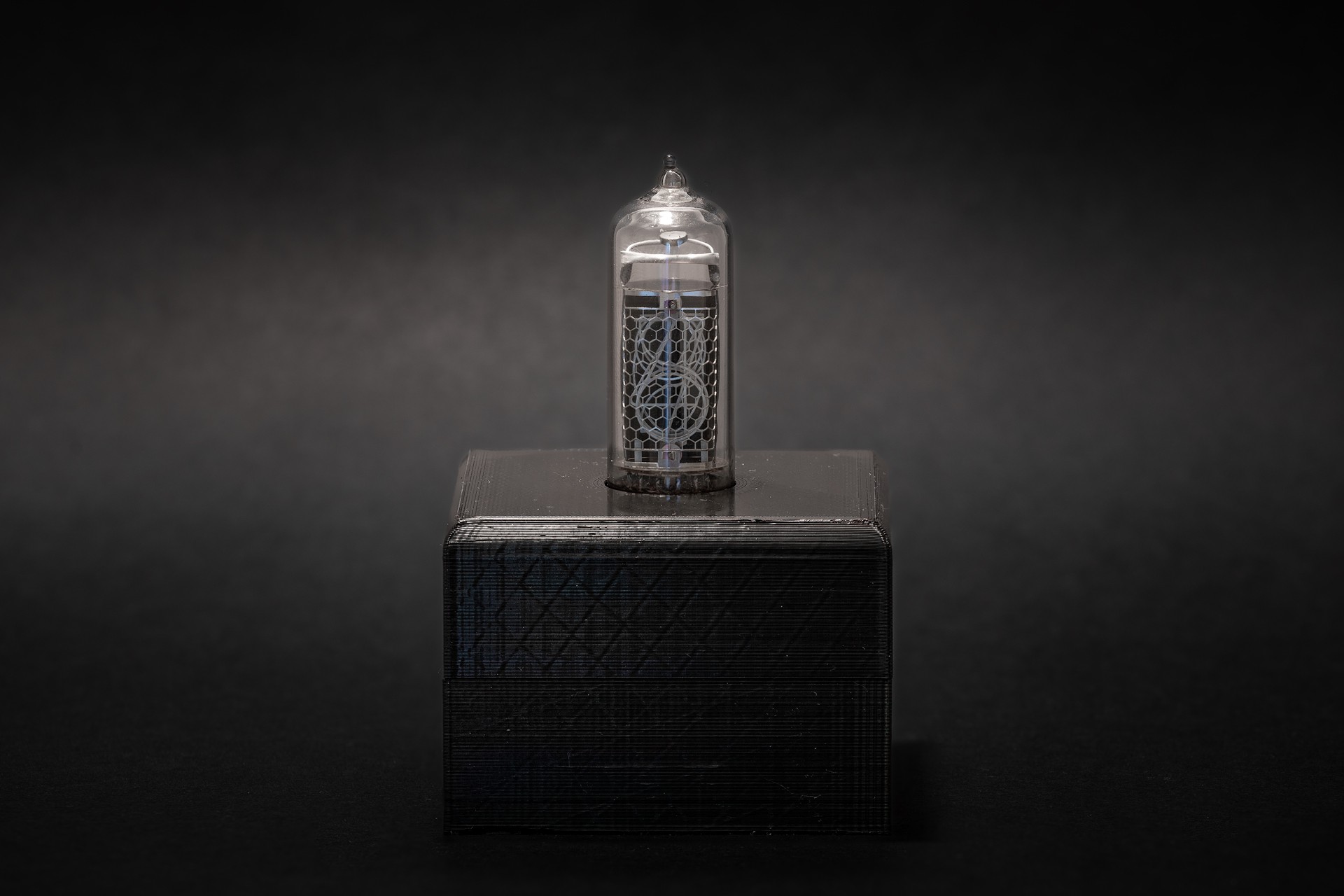
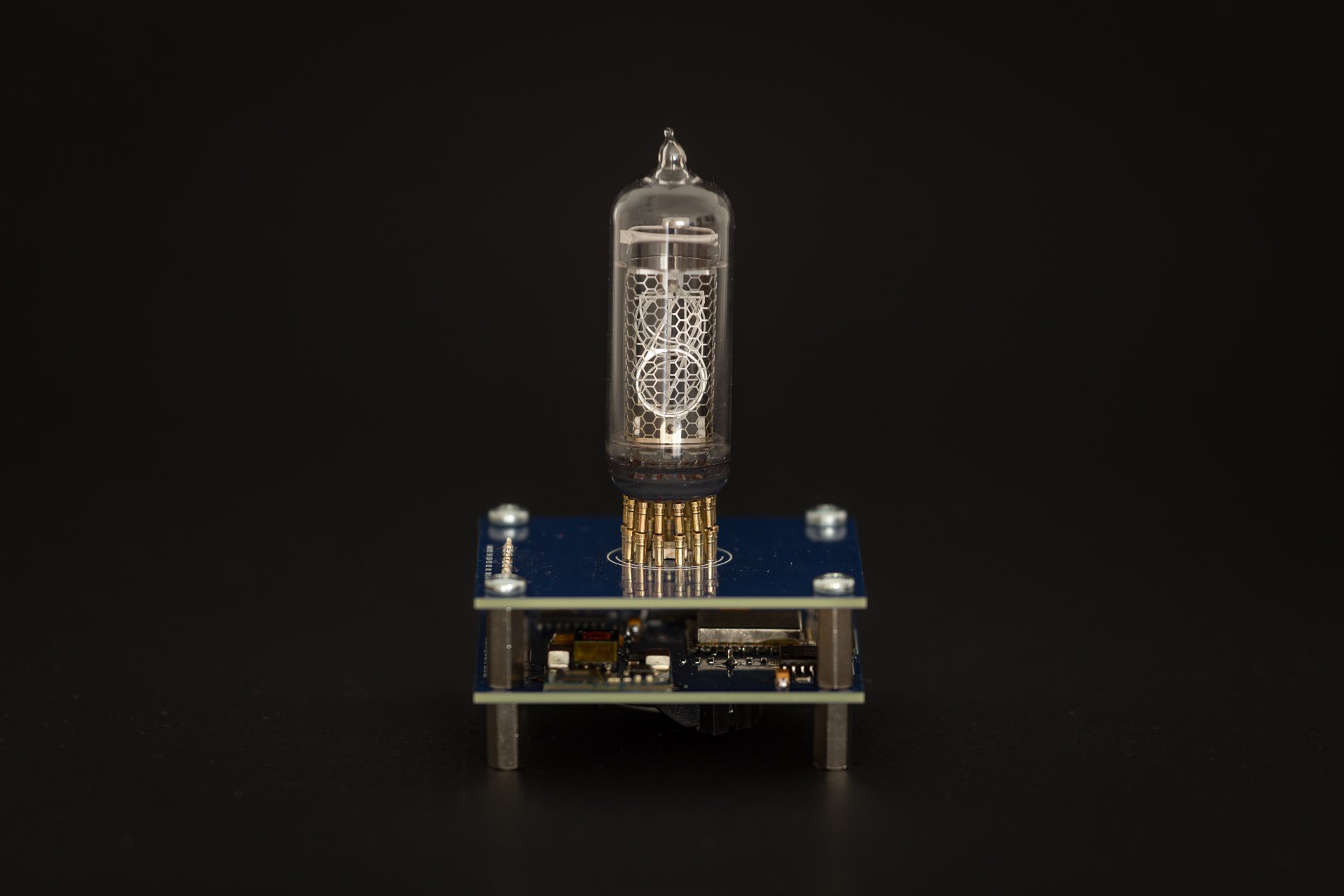
Here is the finished product in its natural habitat:
![]()
The end result is a 3D printed box skinned with chopped carbon and decorated with brass pieces (hinges, ring and latch). The inspiration came from super cars. More and more super (hyper) cars have forged carbon parts. I find this look interesting, dark grey carbon fits nicely with brass. The whole project is a combination of old and new technology, the same case is with the packaging.
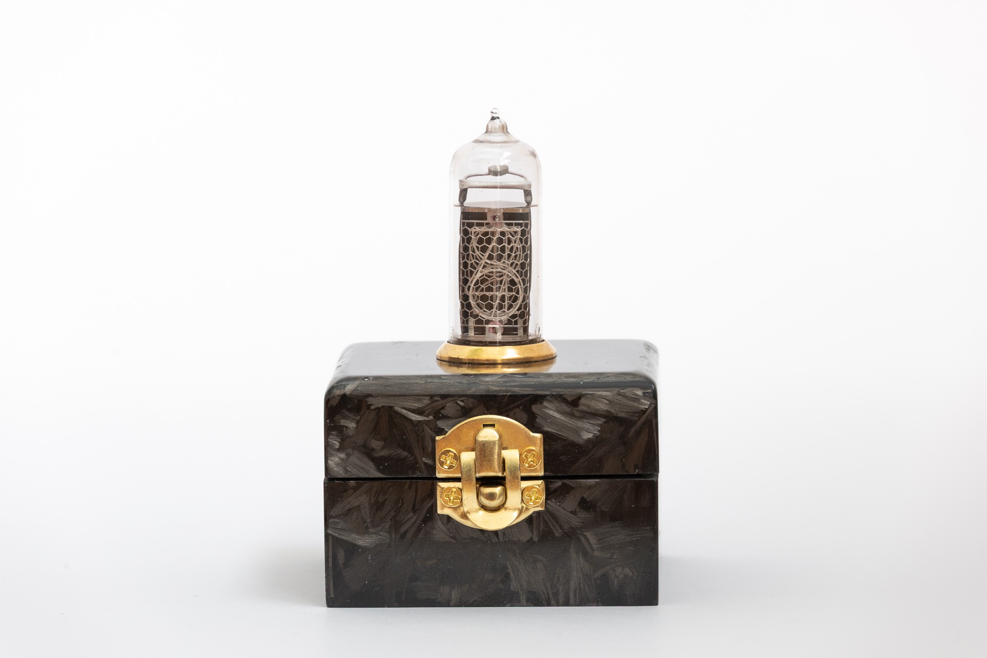
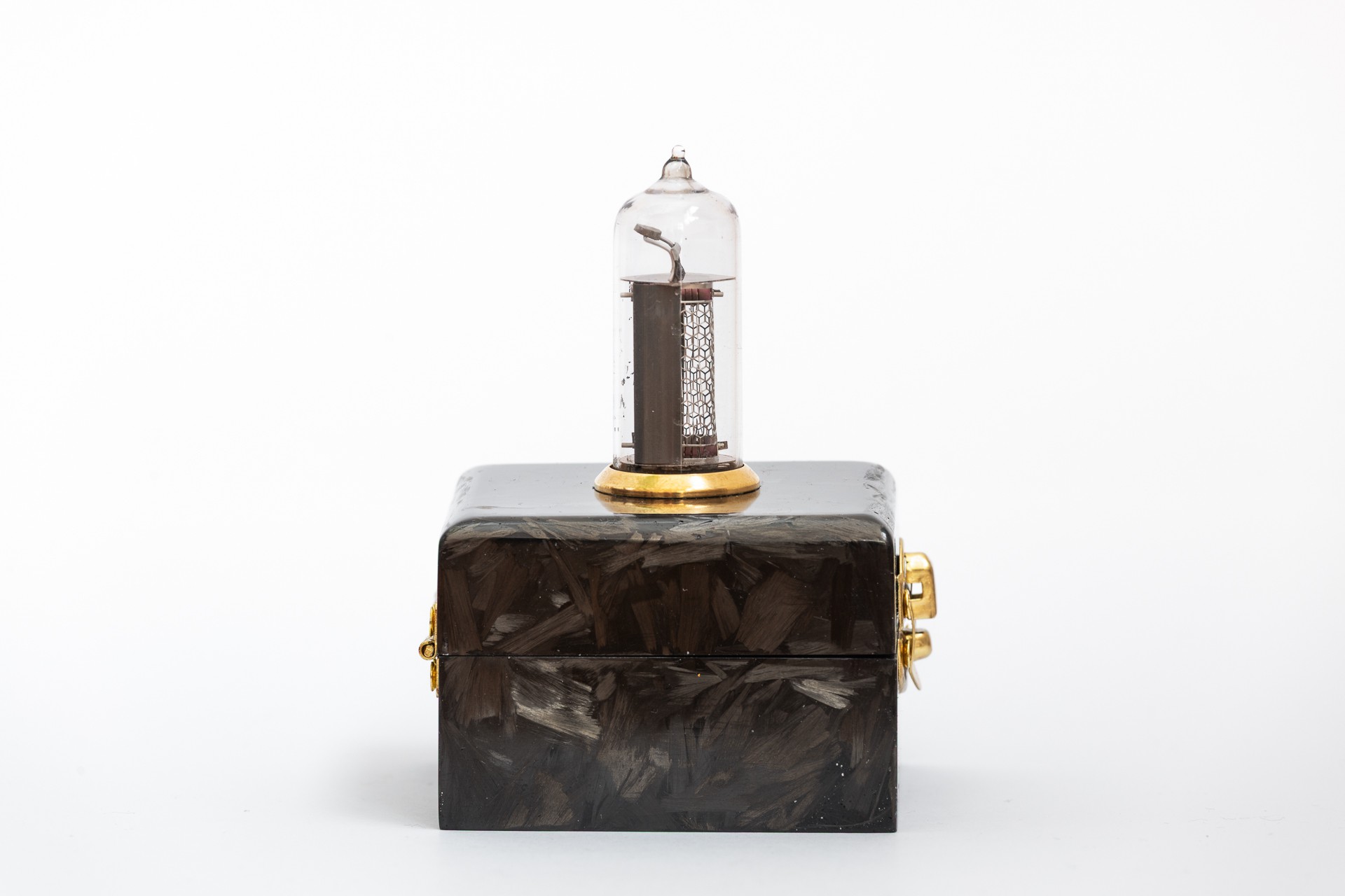
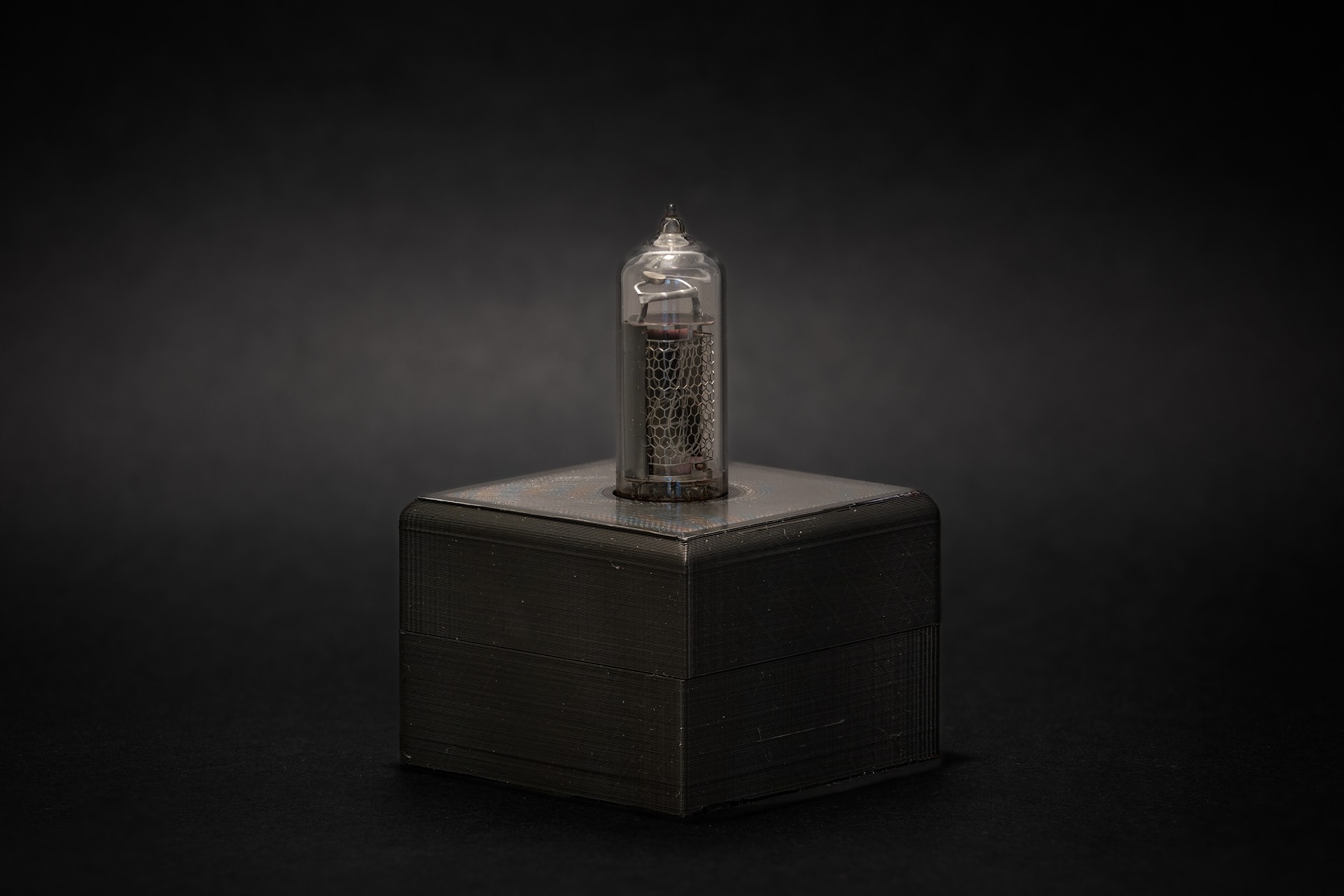
More pictures:
![]()
![]()
![]()
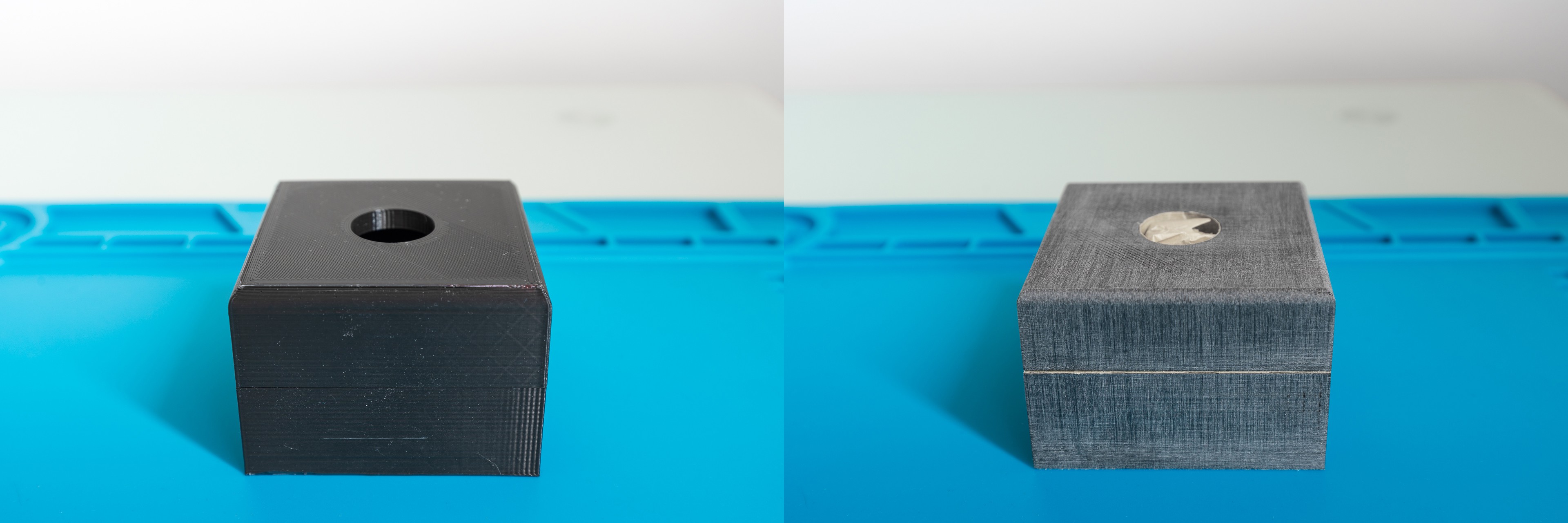
This is how I did it
1. I started with the 3D printed box, sanded it with a 100 grit sand paper to remove printing marks and to prepare the surface for epoxy.
![]()
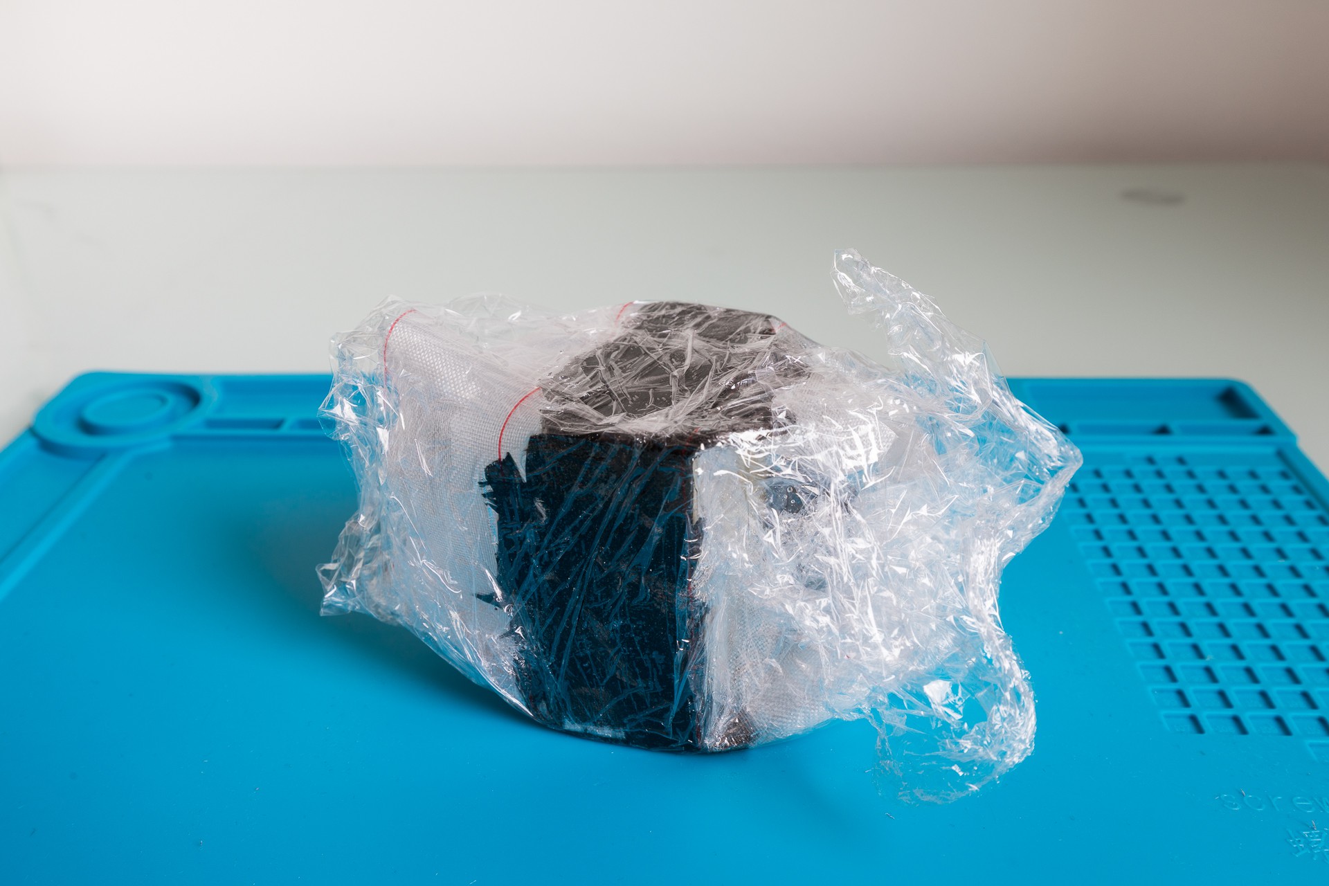
2. Coated the plastic piece with epoxy, covered it with carbon flakes and finally wrap it with peel ply. At the end I covered everything with a nylon foil.
![]()
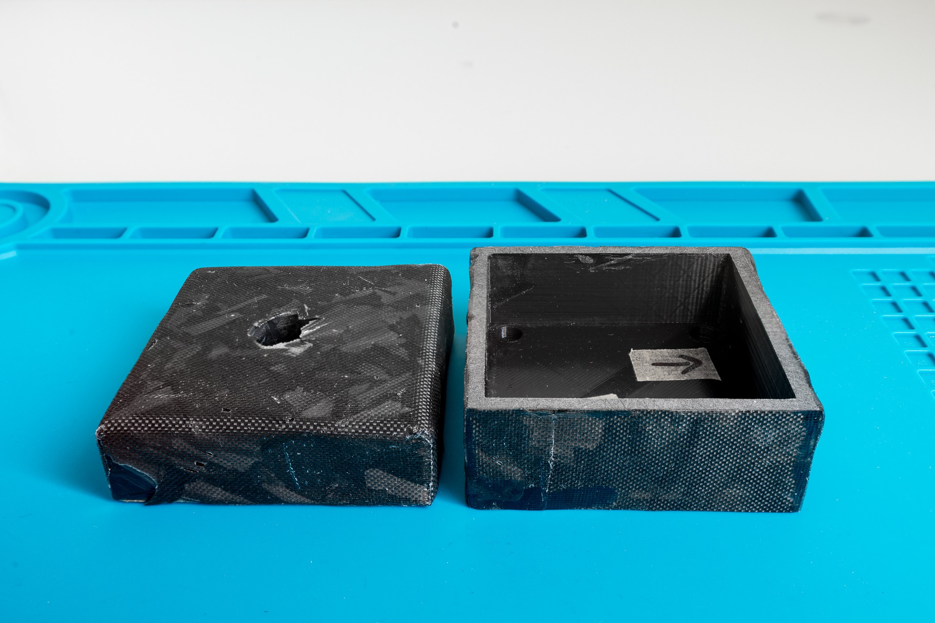
3. Removed peel ply and cut the excess carbon & epoxy:
![]()
![]()
4. FInishing: little touchups, sanding and polishing.
To flatten the faces I used 100-180 grit wet sand papers. Then, I filled the low spots with epoxy. After curing, I continued with sanding with 180, 240, 320, 400, 600, 800, 1000, 2000 grits. Finally, the last step was to hand polish surfaces with 3M fast cut polishuing compound.
-
Project setup & build system update
03/30/2025 at 18:09 • 0 commentsWhile I am experimenting with the clock’s case, I am spending a lot of time idling. To make this spare time more productive, I decided to improve the project by ditching PlatformIO. I find PlatformIO to be a nice GUI tool for development, but I find it cumbersome for project setup. It requires a lot of manual steps to reach the point to be ready to build the firmware. You need to install the plugin in VS Code, setup the ESP/Arduino environment and get all the necessary libraries. Since we are humans, it is easy to forget something or introduce errors.
To solve this issue I opted to replace PlatformIO with a set of tools and ideas to automate this process.
First, I wanted to have full control of all project dependencies including the Arduino core. The main idea was to remove the dependency to the already installed Arduino setup on the host. This is solved with Git submodules. During the setup phase every dependency is being cloned to the thirdParty directory.
Then, I wanted to use makefiles for the build system. Makefiles may look complicated, but they are standing the test of time. IDEs and frameworks are coming and going… To make my life easier, I stumbled upon this project: makeEspArduino
makeEspArduino project simplifies the way of defining project’s Makefile. Just set a couple of variables and include the makeEspArduino.mk and that's it.
To simplify project setup even more, I created a simple setup.sh script. After cloning the repo you only need to call this script to setup the environment. This script will clone all the necessary third party libraries and setup ESP/Arduino environment. No IDE is required.
Here is how to setup the project:
git clone git@github.com:Deni90/singleDigitNixieClock.git
cd singleDigitNixieClock/firmware
./setup.sh
This is how to build and flash the project:
# Build the project
make
# Build and flash the project firmware
make flash
# Build and flash file system:
make flash_fs
To open a serial console
make monitorIt may be overkill, but this way the project can be easily setup on CI.
-
Enclosure design
02/20/2025 at 16:15 • 0 commentsA product without an enclosure is not a complete product. While I enjoy looking at PCBs with all the components of the nixie clock, for others it might be just a dust magnet. The last puzzle piece to complete this project is moving the electronics into a box.
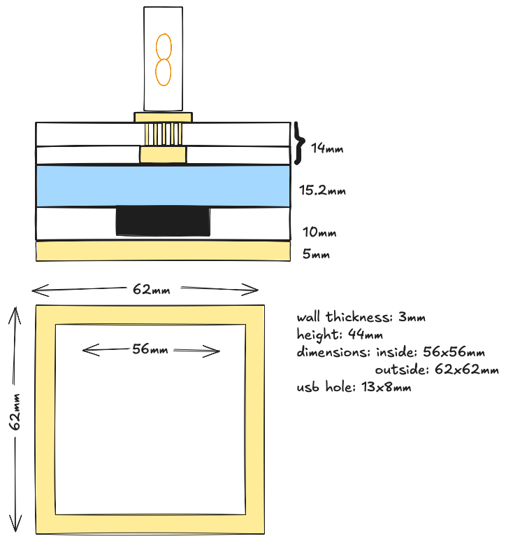
First step is measuring, then getting a rough idea about case dimensions and thickness:
![]()
Second step is CAD, making a design. I opted for a simple box shaped design with holes for the nixie tube and USB connector.
![]()
3D printed prototype:
![]()
![]()
Next step is to think about what material to use and how to make the case more interesting...
-
Hardware - new PCBs (thank you PCBWay)
01/31/2025 at 14:07 • 0 commentsA huge thank you to PCBWay for sponsoring this run of PCBs!
How does this story go?
A representative from PCBWay contacted me because he was deeply impressed by my project and offered to sponsor a batch of PCBs to test out their services.
Firstly, I was surprised since no one ever showed interest in my personal projects. He was very kind to explain what they offer through the sponsorship and we made a deal.
I have to be honest, I was a bit sceptical how this would go. It turned out they were very professional by sending the boards and paid all necessary costs including delivery. In addition to this, I have to praise simple and easy ordering through their website.
Since I recently moved to KiCad, it was a perfect opportunity to try out the PCBWay Plug-in for KiCad. It provides a simple way to place an order in just a few clicks. There is no need to bother with exporting gerber files, everything is automated. You just need to update the PCB specification and fill in the shipping information on the webpage. That’s it.
Another useful tool is PCBWay’s online gerber viewer, it is good for double checking all the exported files and to use images of PCBs in documentation.
The entire journey from placing the order to receiving the package took less than a week. Incredible! PCBWay did a superb job, PCBs are amazing.
![]()
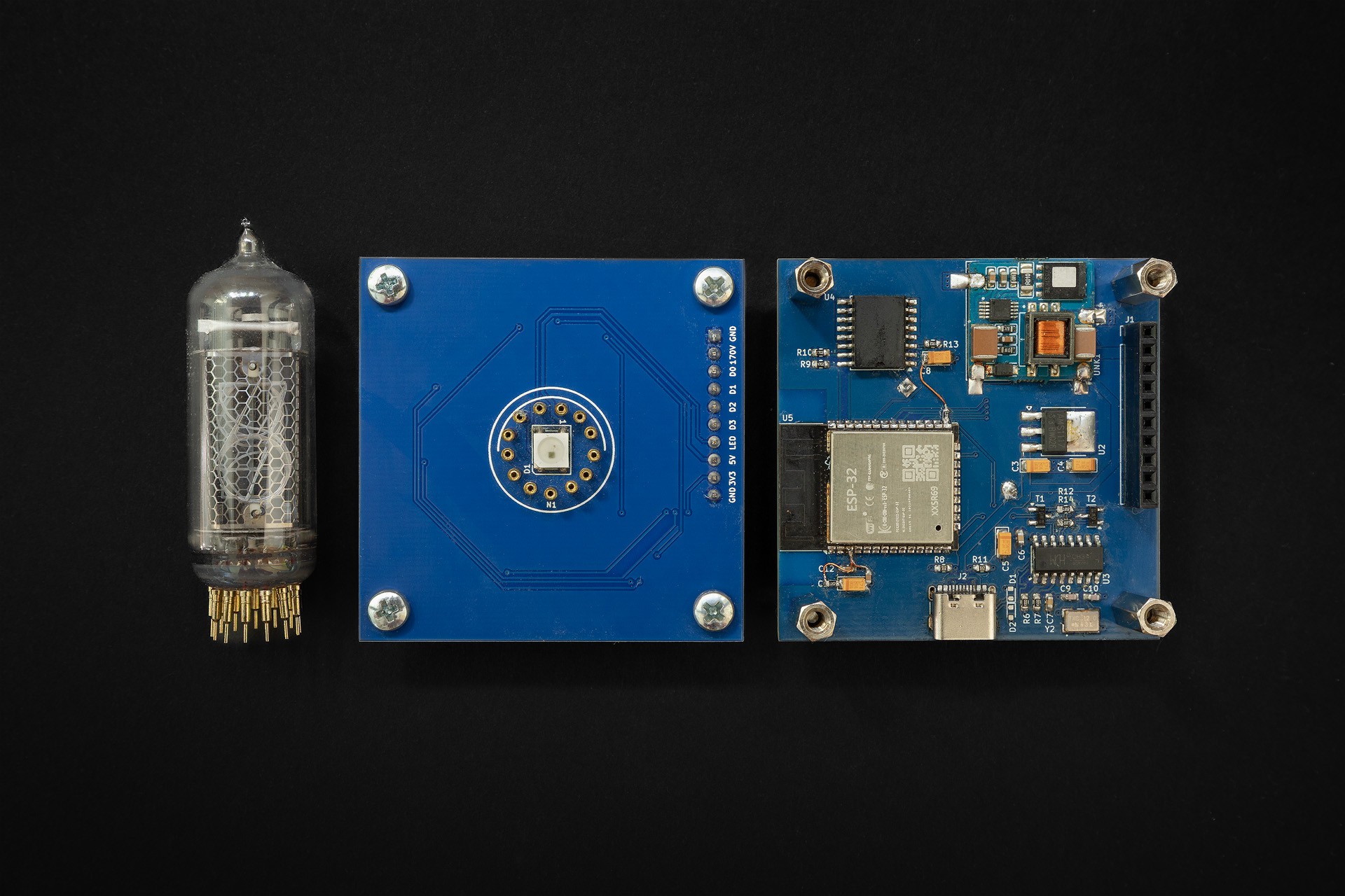
Assembled PCBs:
![]()
Stacked PCBs:
![]()
Updates on Control board
Micro USB connector has been replaced with a type C connector. Nowadays, it is much easier to find type C cables at our desks because almost all devices switched to it. Despite it being harder to solder this connector without stencils, I found this change a logical step to keep up with current trends.
Here is the updated part of the control board:
![]()
Control board schematic is updated in the project's details.
Lessons learned from this batch
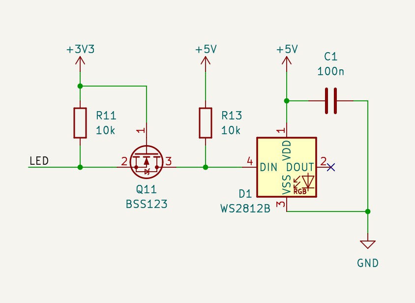
Weird behaviour of the WS2812B RGB LED:
![]()
I initially thought the problem was in micro USB connectors because the problem occurred with some cables. But, then I realised the problem might be in the fact that WS2812B is rated to 5V and the signal coming from ESP is 3V3. The LED worked on the breadboard while I was experimenting. I remember, I read somewhere that that’s fine… But, it isn’t. To fix this issue I’ve added a level shifter before the DIN pin of the RGB LED:
![]()
Here is my botched PCB:
![]()
-
Hardware - Display board [v2]
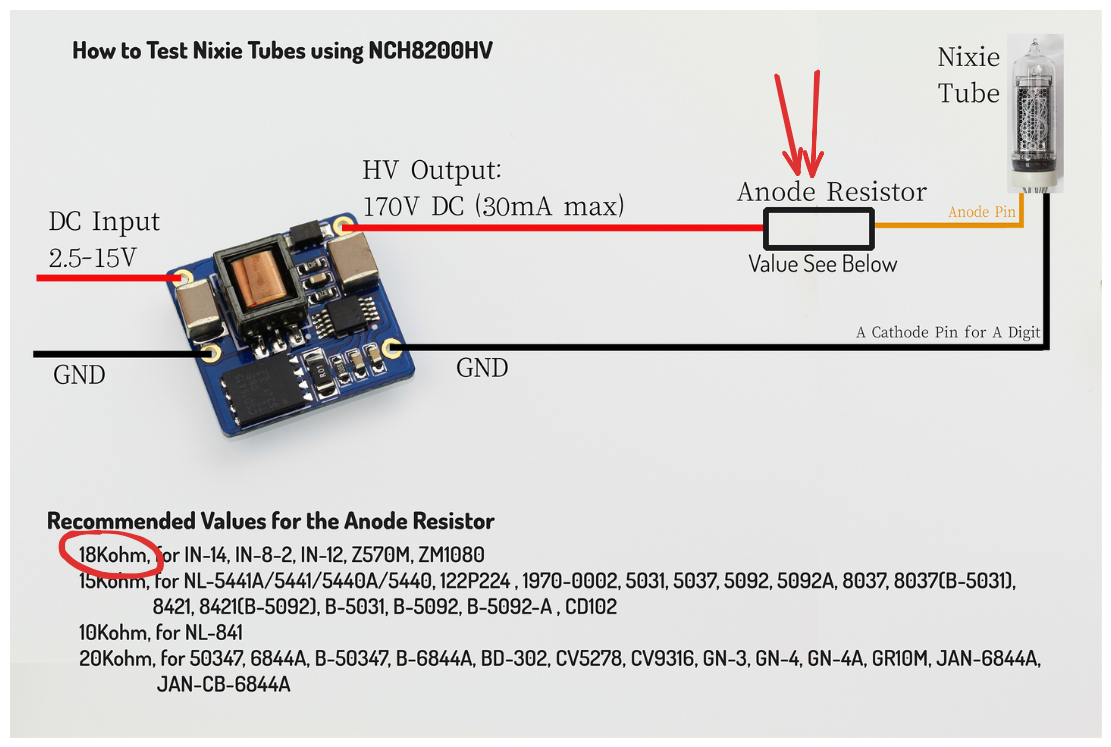
01/20/2025 at 13:24 • 0 commentsRecently, I decided to move schematic & PCB designs from the good old, but sadly dead EaglePCB to KiCAD. I found this exercise good for learning how KiCAD works. While I was replacing components with ones from KiCAD I double checked data sheets and docs… Documentation for NCH8200HV has a wiring diagram describing how to connect a nixie tube to the 170V supply module. In the picture below there is an anode resistor that is used as a current limiter. I completely missed that. That’s the reason why the digits were too bright. The second thing I learned is to never overcurrent Nixie tubes.
![]()
To solve this issue, I cut the 170V trace on the display board and soldered an 18K resistor in series:
![]()
Updated schematic is in the project's details.
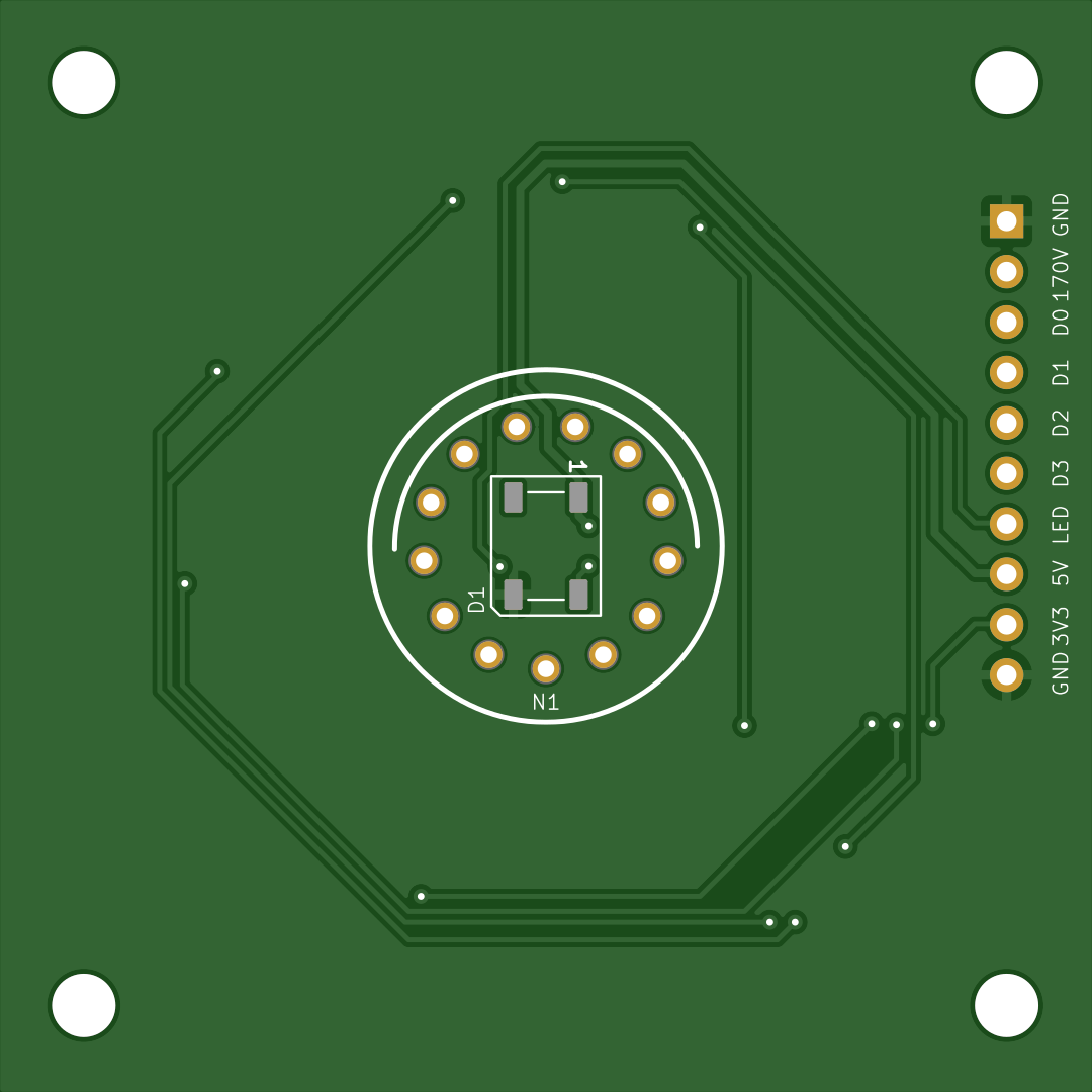
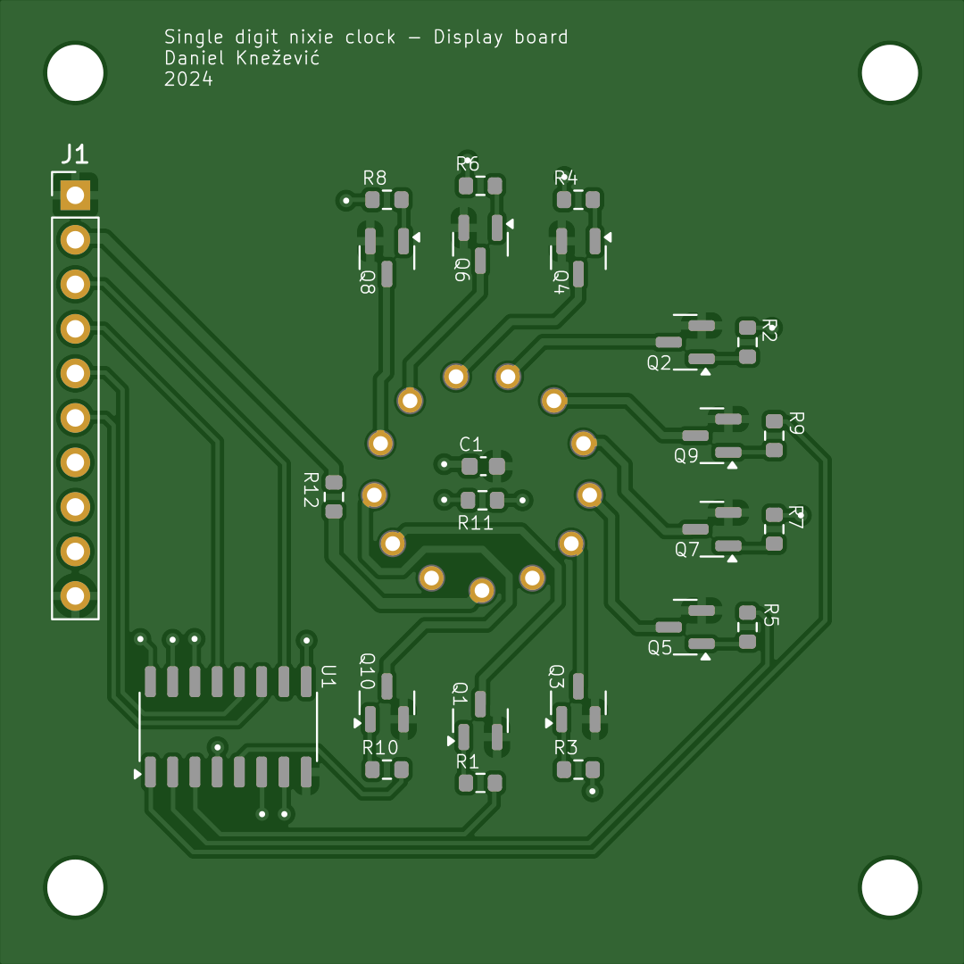
PCB
![]()
![]()
-
Web server
01/15/2025 at 16:31 • 0 commentsBackend
Backend is implemented using ESPAsyncWebServer.
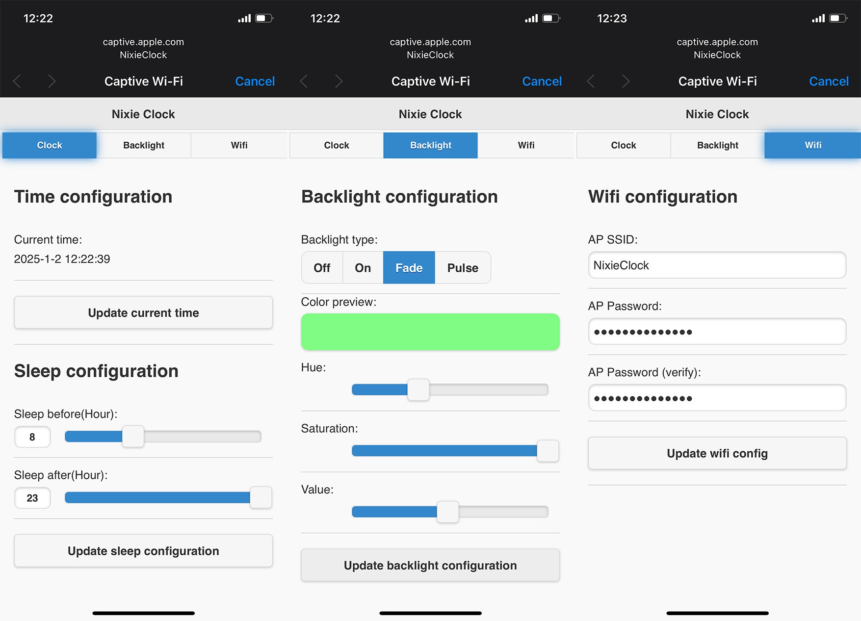
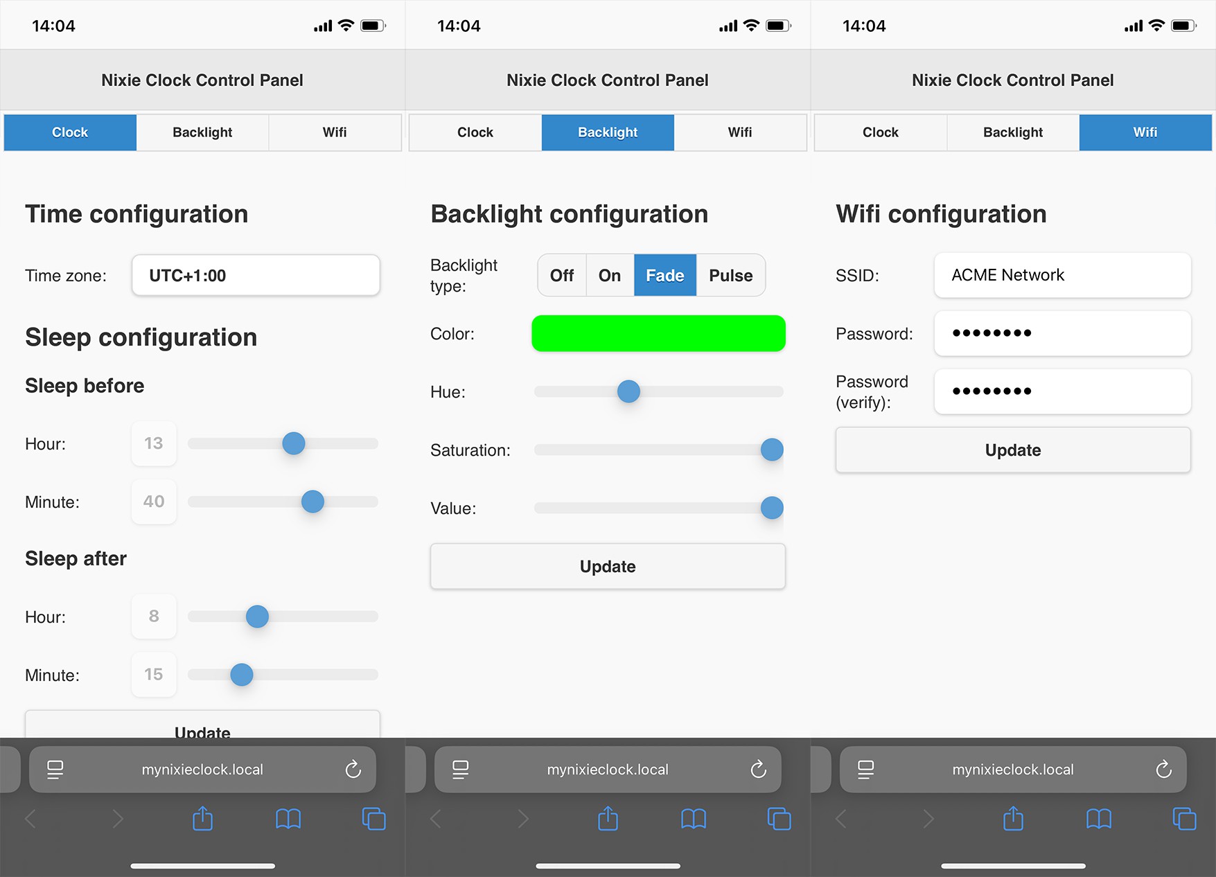
Frontend design
Initially, the front end was implemented with jQuery mobile. Reason for choosing this framework was in its simplicity. It provides a simple way to create and control user interface components. One thing that always annoyed me was its low response time. It took too much time to load jQuery, jQueryMobile and theme resources. On top of this, this slow response time caused WDT resets.
One more thing, I just realised that jQuery mobile project is deprecated since October 7, 2021. Huh, when it comes to web related technologies, it looks like I'm living under a rock...
To solve these issues, I opted to completely re implement the frontend using plain HTML, CSS and JavaScript. The end result looks almost the same as the previous design or even better. Responsiveness and stability increased significantly. The only drawback is now in maintenance and extension. It is required to implement everything manually.
Size comparison
jQueryMobile implementation Custom implementation Improvement 404kB 32kB 1262,5% Performance comparison
Average loading time of 10 tries:
jQueryMobile implementation Custom implementation Improvement 8695mS 879mS 988% Note: The jQueryMobile implementation caused restart of the ESP 3 times.
Design comparison
jQuery mobile design:
![]()
Custom design:
![]()
-
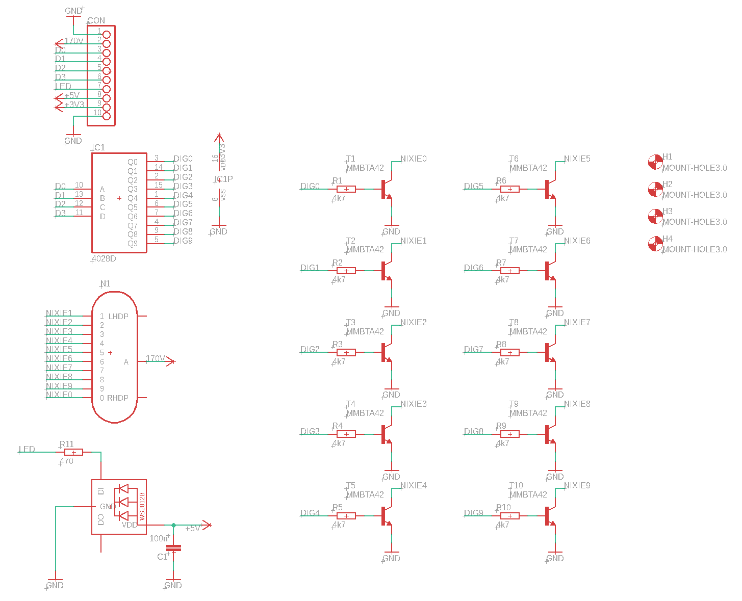
Hardware - Display board [v1]
01/07/2025 at 10:58 • 0 commentsDisplay board uses a CD4028 BCD-to-decimal decoder. Its purpose is to reduce the number of required GPIO pins from 10 to just 4 for showing digits from 0 to 9. Compared to dedicated BCD to decimal decoder nixie drivers (like K511ID1), the CD4028 is a widely spread component and it is available in SMD package. Since CD4028 has a voltage range from 3.0V to 15V it is not compatible with nixie tube’s operating voltage of 170V out of the box. This problem is solved with MMBTA42, a high voltage transistor, rated to more than 200V.
The rest of the display board consists of a WS2812B RGB LED and a pin header used to connect with the control board.
Schematic
![]() PCB
PCB![]()
-
Hardware - Control board [v1]
01/03/2025 at 15:57 • 0 commentsFor proof of concept NodeMCU was connected with a DS3231 RTC module on a breadboard. This was enough to start working the firmware. Later, a PCB was created. The PCB is basically a re-packaged NodeMCU design connected with DS3231 and NCH8200HV high voltage boost module board.
![]()
Schematic
![]() PCB
PCB![]()
Single Digit Nixie Clock
A small project combining ESP32 with a vintage Soviet Nixie tube from the 70’ to create an artistic clock


 PCB
PCB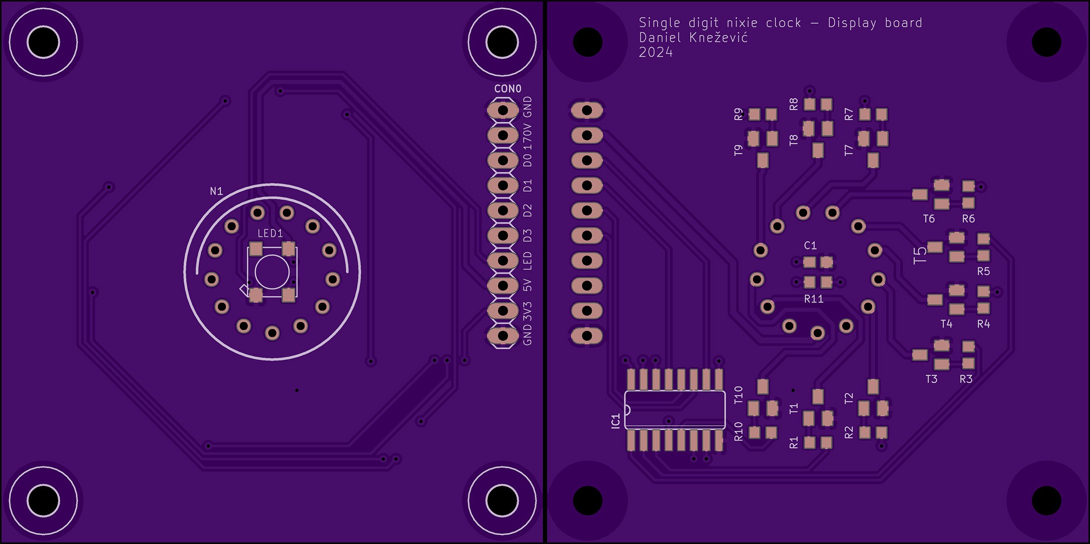
 PCB
PCB