Close
0%
0%

Batocera Arcade Box

Made a simple Batocera-based Game emulator Station using a LattePanda V1

Similar projects worth following
Greetings everyone and welcome back, Here's something fun and nostalgic. Right now, we are using our recently developed Batocera Arcad Box to run Roadrash using a PS1 emulator.
We're using Batocera Linux, which is an open-source and completely free retro-gaming distribution designed to turn any computer or single-board computer into a gaming console.

Here, we booted Batocera on our fairly old Latte Panda V1 single-board computer, which was released in 2015 and had an Intel Atom x5-Z8350 quad-core processor with 4GB DDR3L RAM. This processor was powerful for an SBC at the time, but it is not very effective today if we want to use it to run Windows effectively.

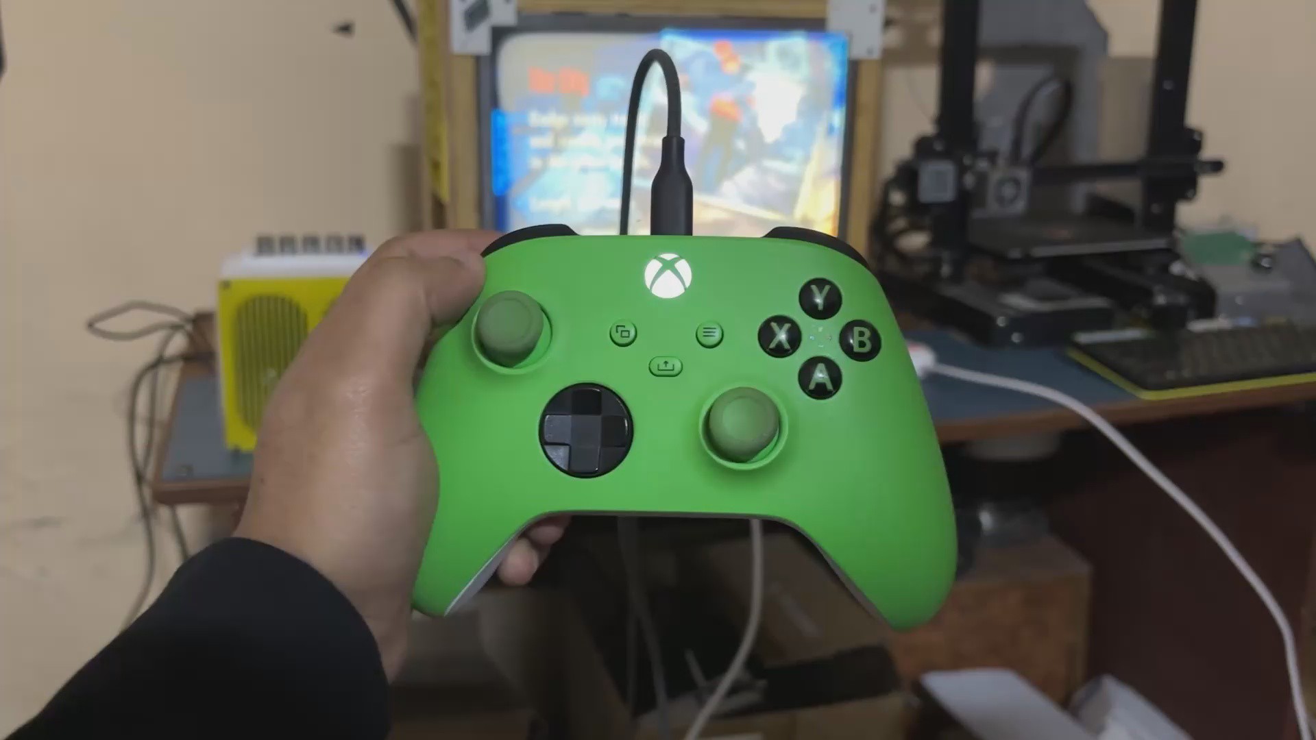
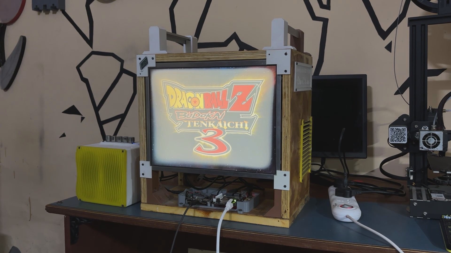
Making a retro arcade that can simulate systems like the PS1, PS2, PSP, SEGA, Gameboy, and others without breaking a sweat was one of the best uses for this old SBC.

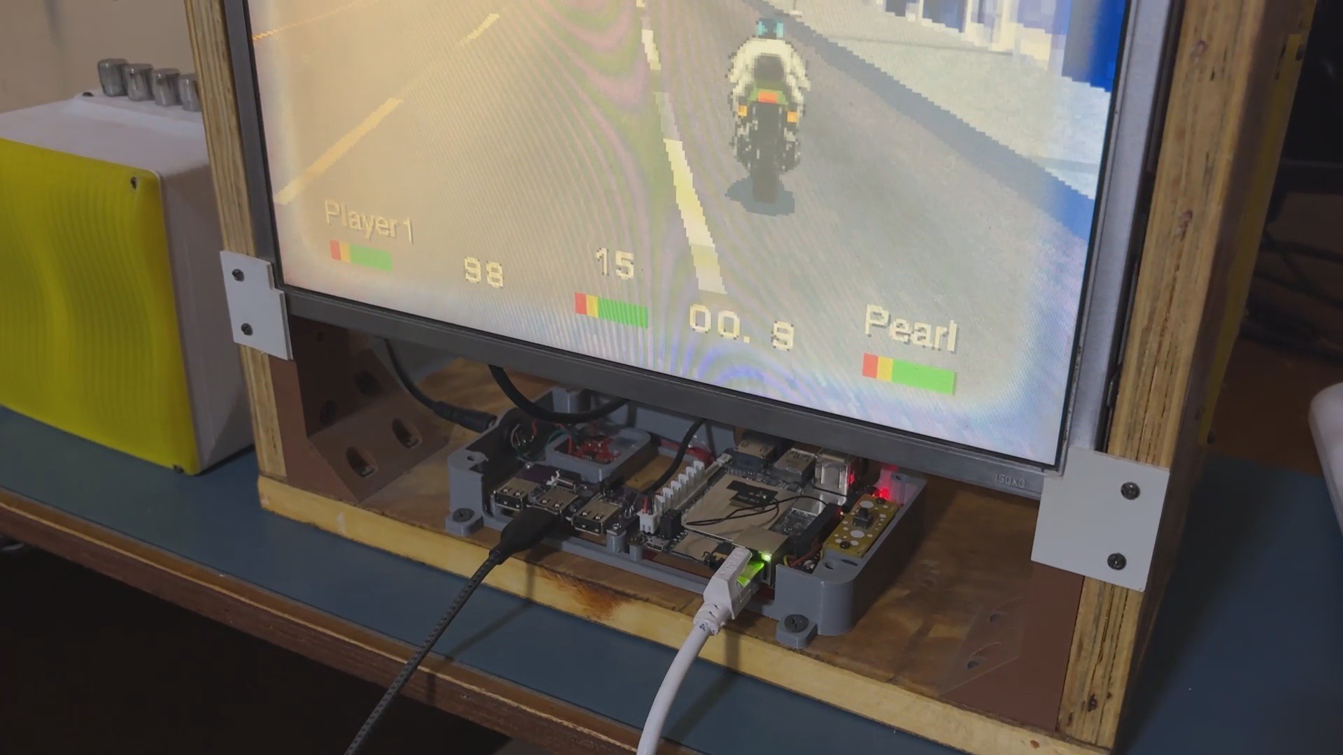
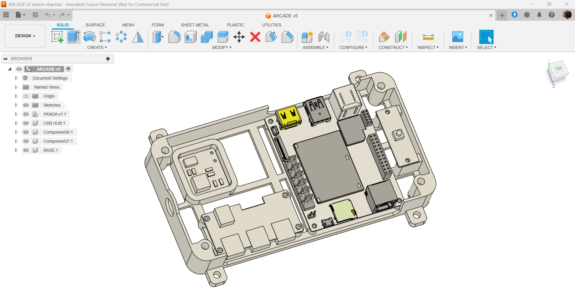
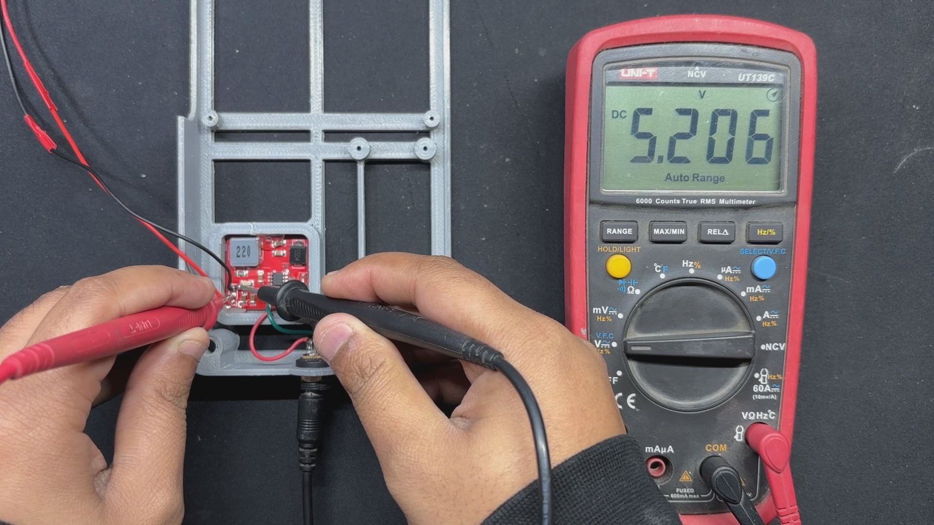
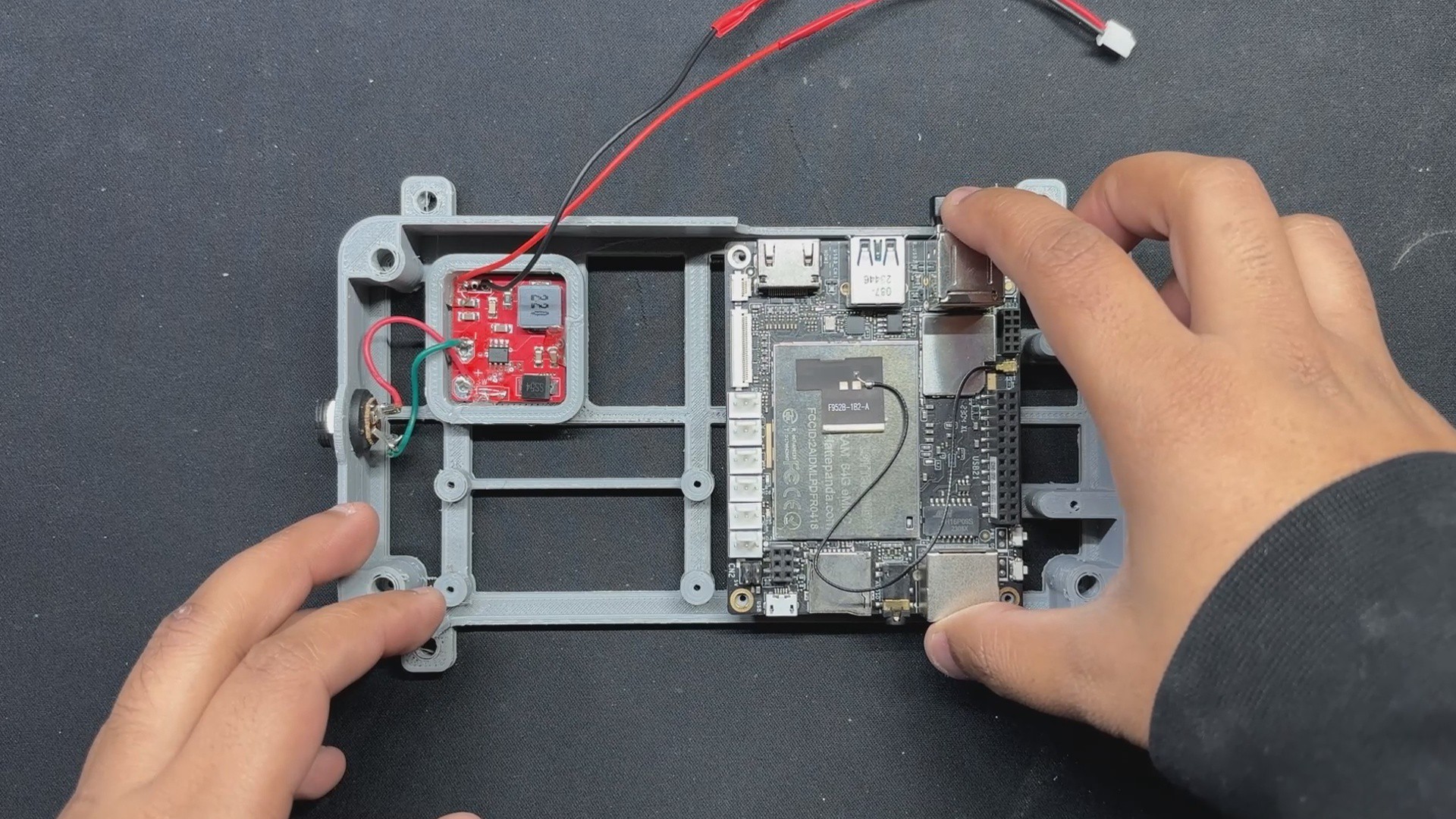
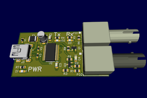
We created a compact box-like enclosure that holds the Latte Panda V1, a USB Extender Hub that allows us to connect multiple controllers to this device for multiple players, and a specially designed power circuit that requires 12V input and provides a steady 5V/3A output to operate the Latte Panda to its maximum capacity.

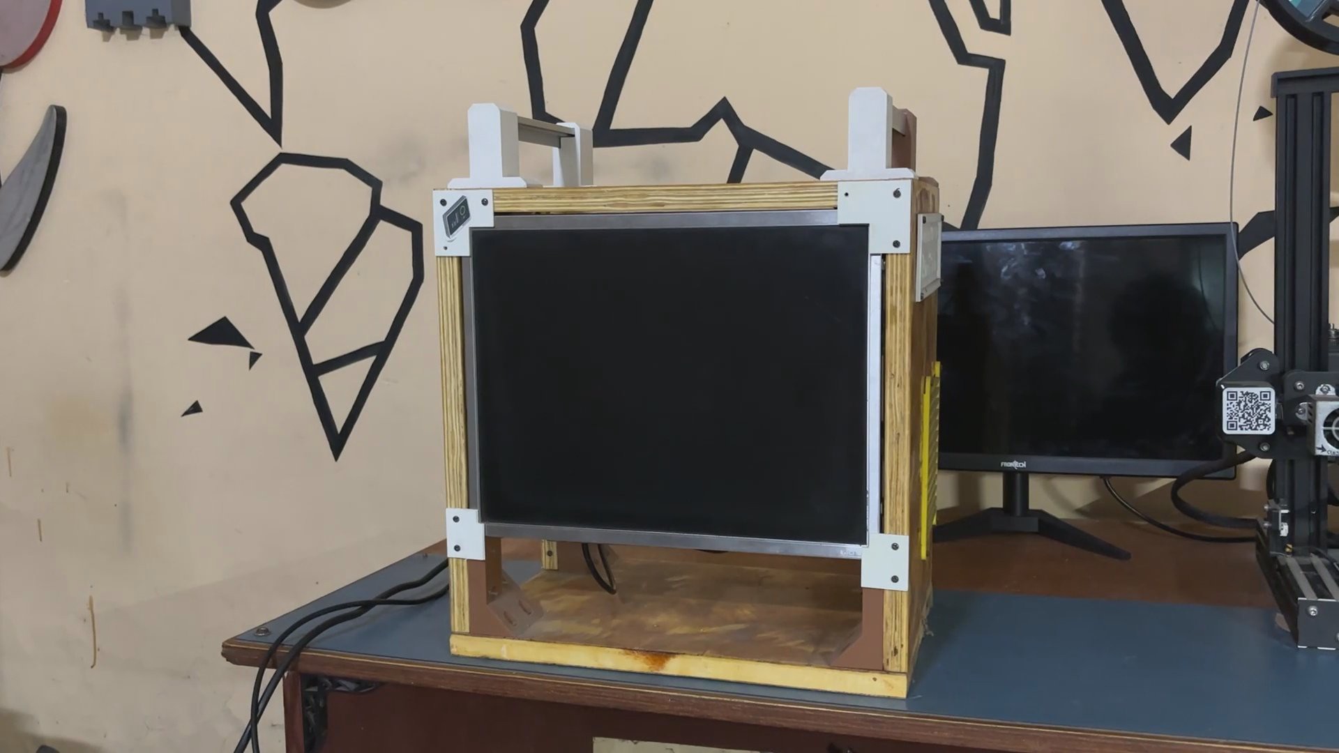
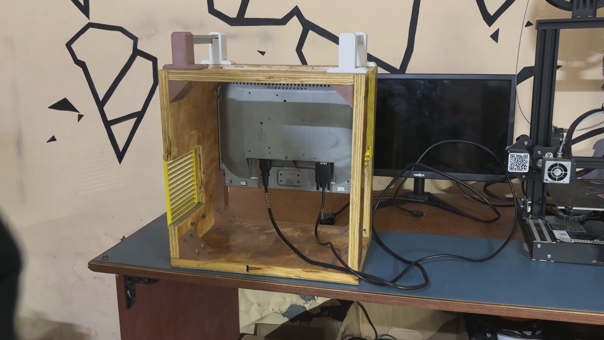
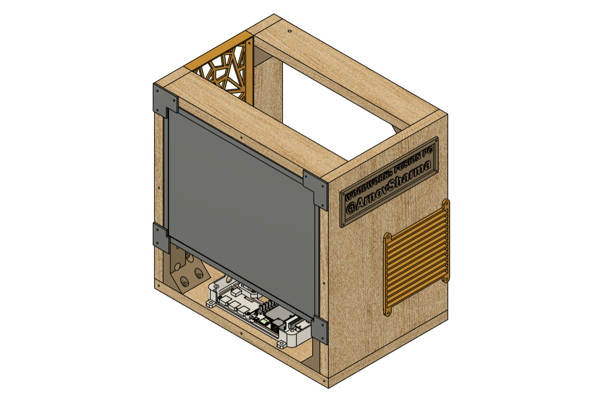
We used one of our previous projects, the woodwork fusion, for the project's body and screen. To provide room for the arcade box, the PC's motherboard and other components were taken out.

After that, we put our arcade box inside the PC frame and put everything together to create the ideal arcade system that runs Linux and Batocrea.

This article is about the whole build process of this project, so let's get started with the build.

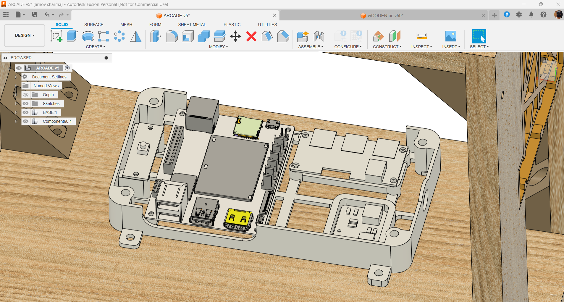
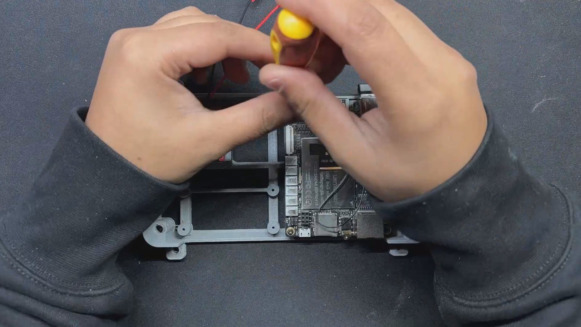
LattePanda V1 x86 Single Board Computer

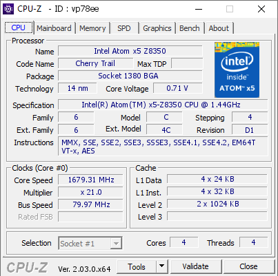
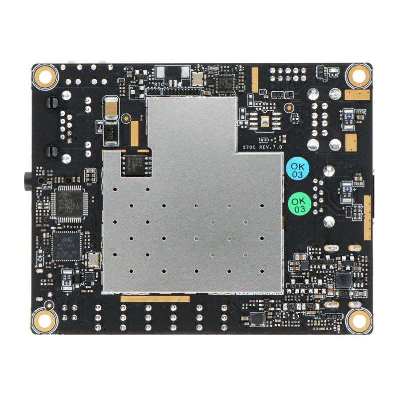
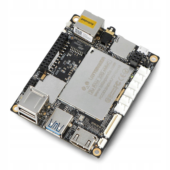
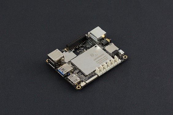
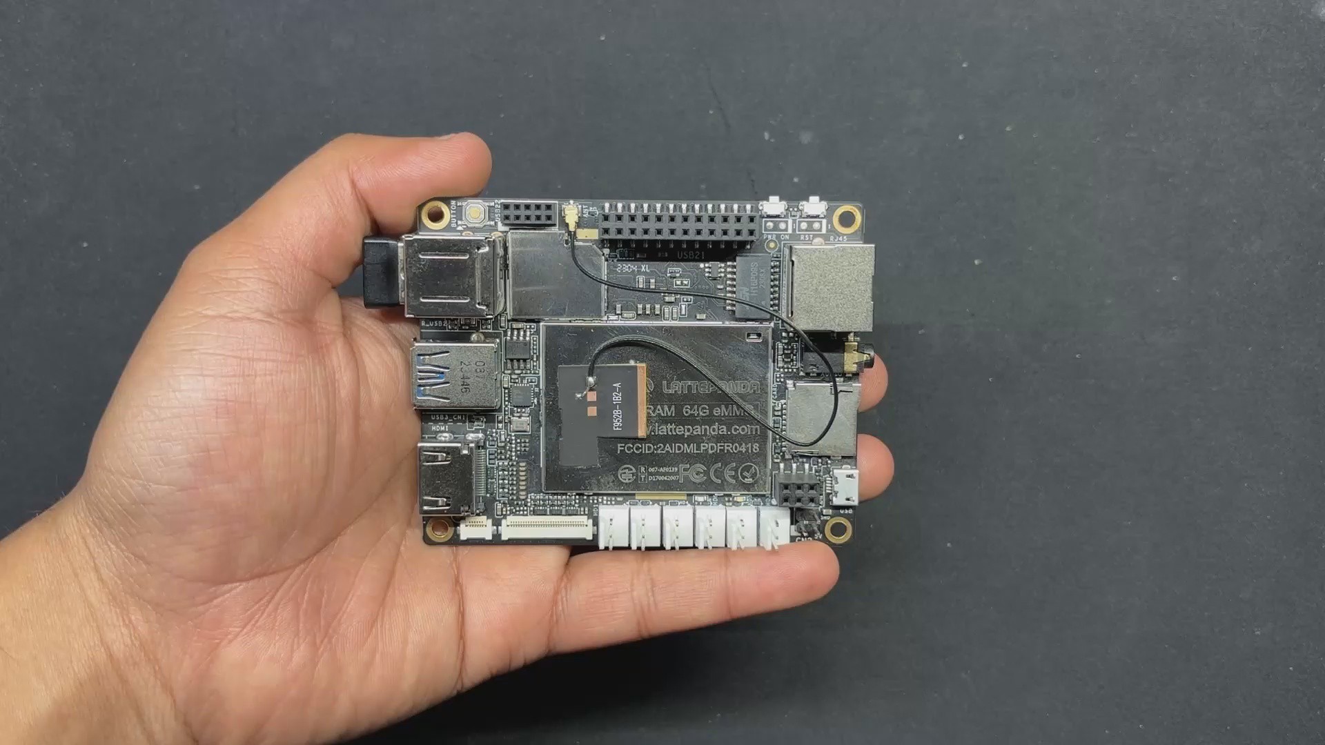
We opted to use the LattePanda V1, a single-board computer featuring an Intel Atom x5-Z8350 quad-core processor running at 1.8 GHz, 4GB of RAM, and 64GB of onboard storage, for our project.

This little device's x86 processor allows it to run a variety of Linux operating systems alongside Windows.

It comes with two varieties. 2GB RAM, 32GB storage, and 4GB RAM, 64GB storage; we are using the 4GB variant.

In terms of connectivity, this board has two USB 2.0 ports, one USB 3.0 port, HDMI output, onboard WIFI, Bluetooth 4.0, and an upgraded ATmega32u4 Co-processor that allows us to add sensors and modules. In other words, we can use the onboard Co-Processor as an Arduino device.

For more information about the SBC, you can visit the wiki page published by DFrobot, the company that made this device.

https://docs.lattepanda.com/

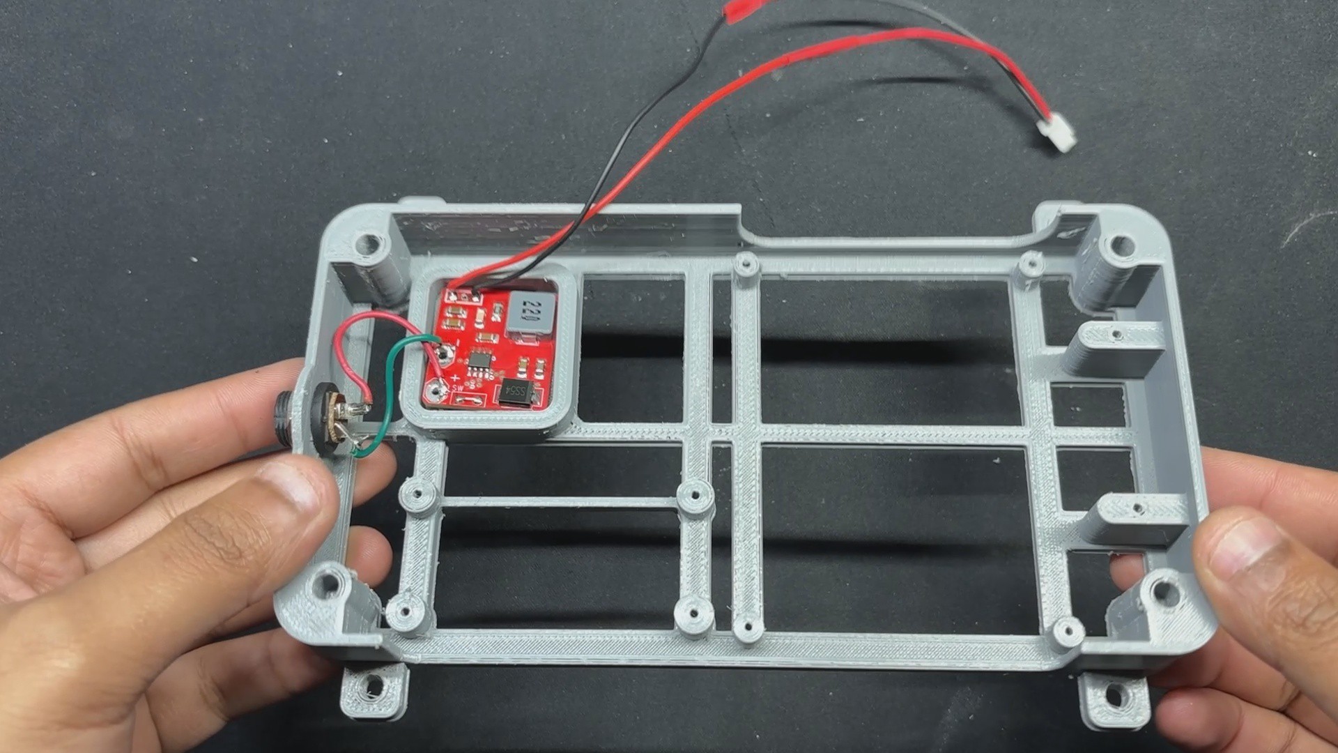
Power Source Circuit

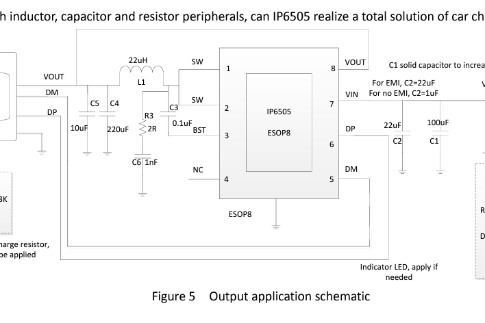
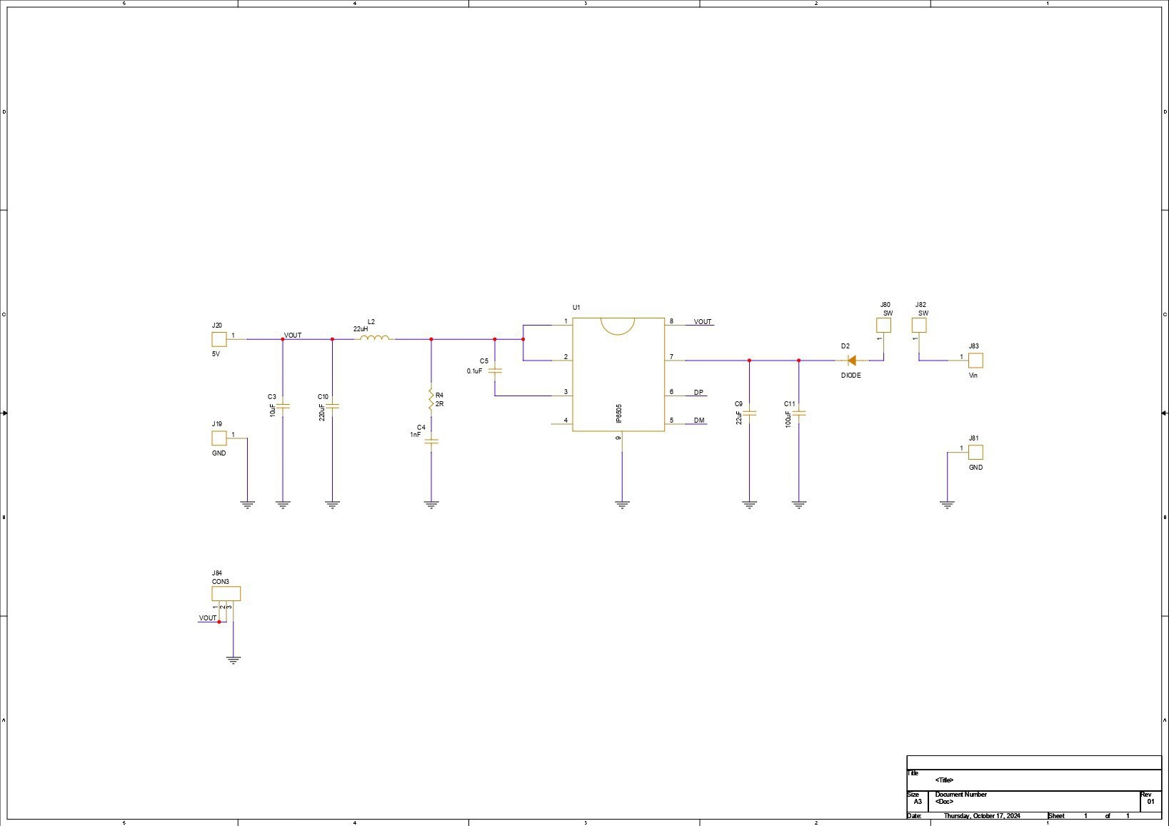
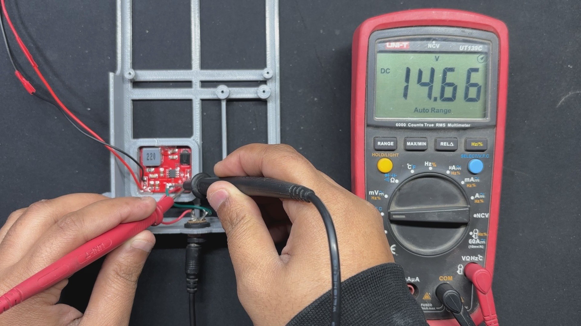
For the power circuit, we opted for a Buck Converter setup in which we have chosen the IP6505 IC, which is a step-down converter with an inbuilt synchronous switch that can handle an output of up to 10A for fast charging protocols. This is the project's main appeal.

An integrated power MOSFET with an output voltage range of 3V to 12V and an input voltage range of 10.5V to 28V is a feature of the IP6505. By automatically altering the voltage and current in accordance with the recognized rapid charge protocol, it can produce up to 24W of output power, which is plenty for our Latte Panda V1.

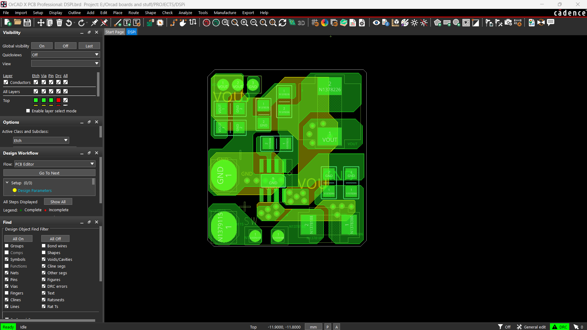
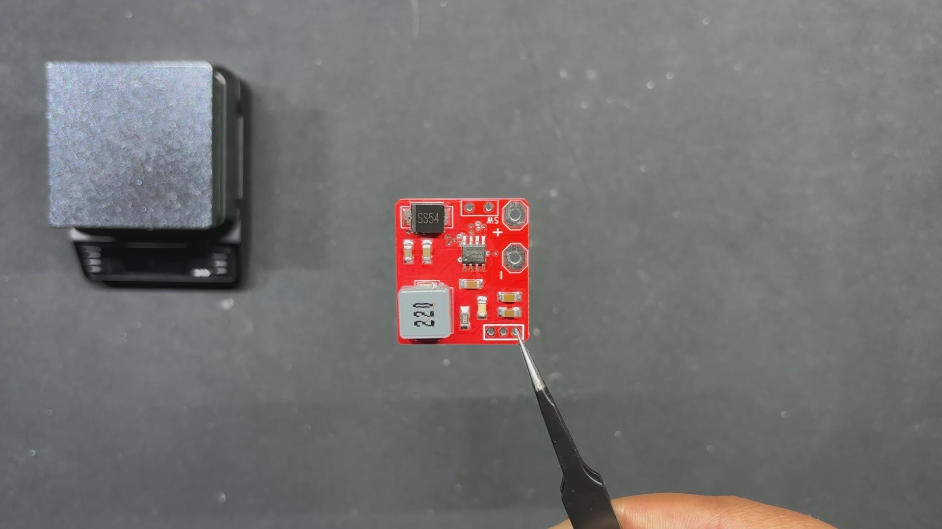
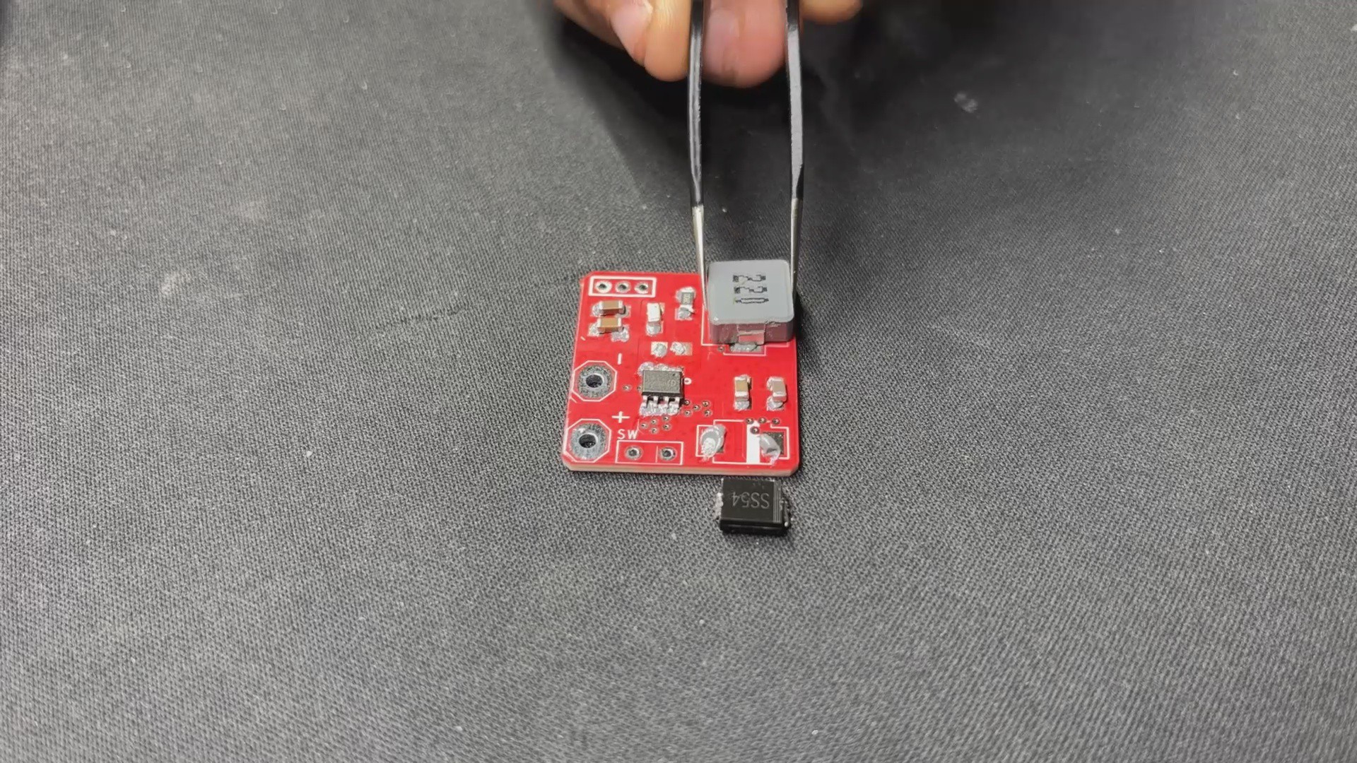
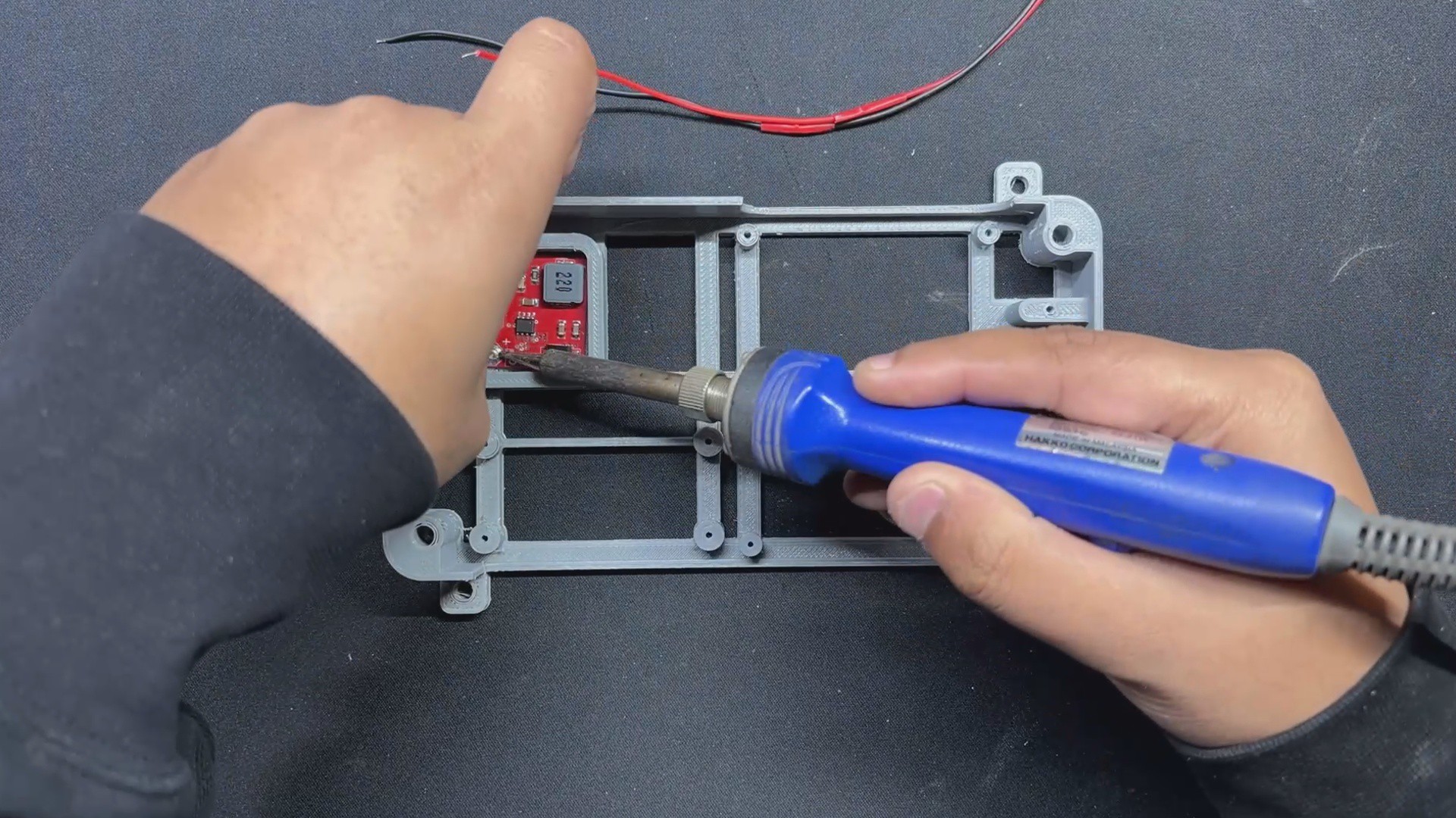
We produced a little Buck converter board with this setup because we had previously used it and found it to be quite easy to work with.

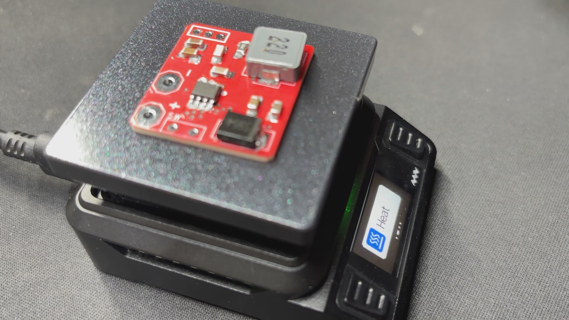
The schematic was originally created and set up using the datasheet's example layout. All of the components on this board are surface mount, which minimizes the need for manual soldering, including the mounting of through-hole components.

PCBWAY Service

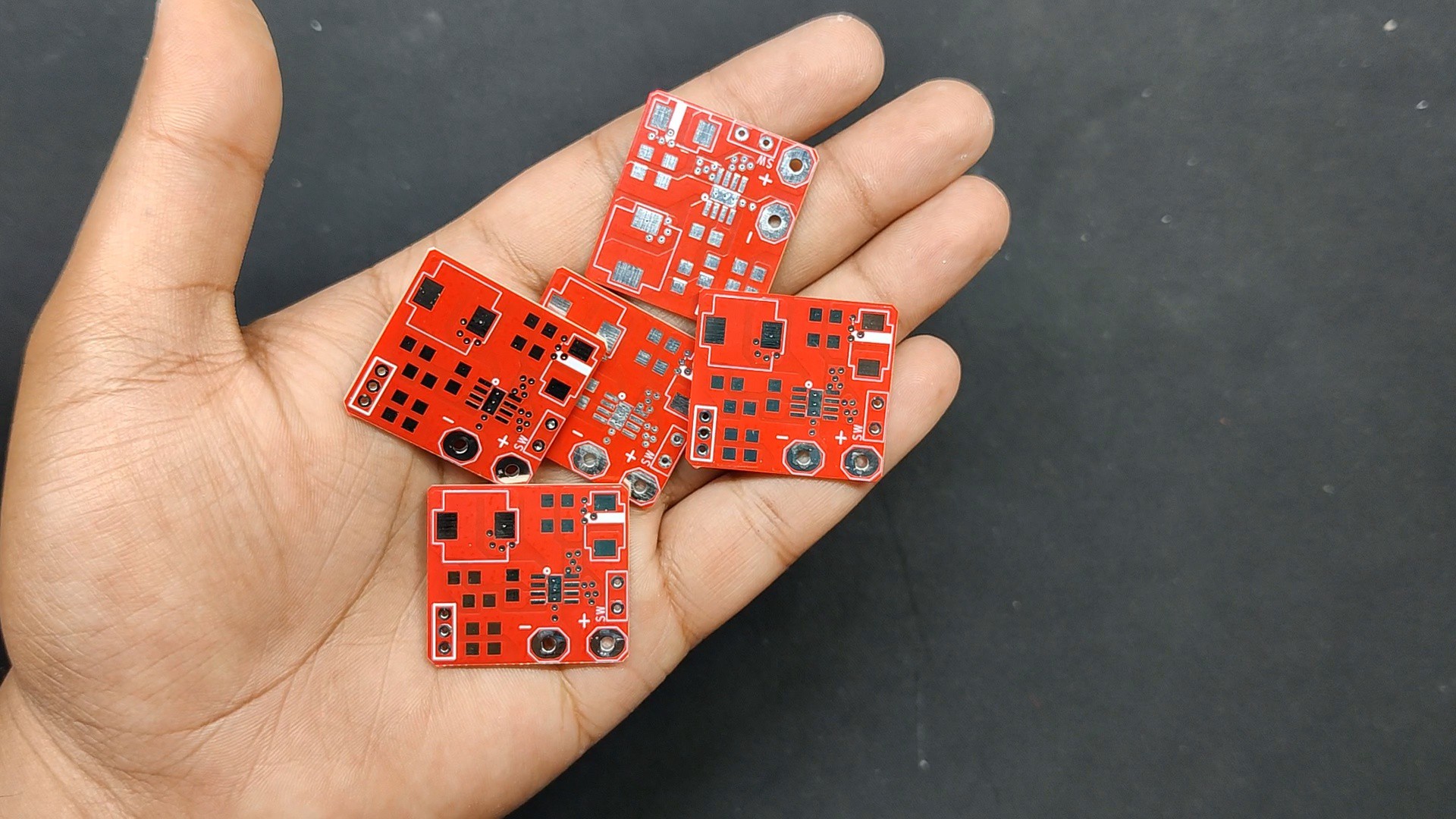
After completing the PCB design, we export the Gerber data and send it to PCBWAY for samples.

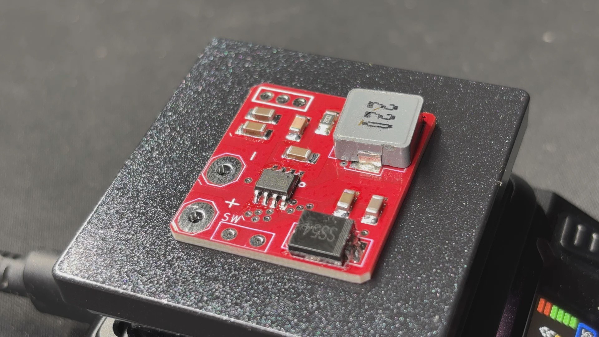
We placed an order for a Red Soldermask PCB with white silkscreen.

After placing the order, the PCBs were received within a week, and the PCB quality was pretty great.

Over the past ten years, PCBWay has distinguished itself by providing outstanding PCB manufacturing and assembly services, becoming a trusted partner for countless engineers and designers worldwide.

Their commitment to quality and customer satisfaction has been unwavering, leading to significant growth and expansion.

You guys can check out PCBWAY if you want great PCB service at an affordable rate.

ARCADE v7.step

step - 22.11 MB - 01/04/2025 at 18:50

Download

body.3mf

3mf - 157.14 kB - 01/04/2025 at 18:50

Download

SCH.pdf

Adobe Portable Document Format - 101.51 kB - 01/04/2025 at 18:50

Preview

  • 1
    PCB Assembly Process
    • We begin the power board assembly process by adding solder paste to each component pad.
    • Next, we use an ESD Tweezer to pick and place each component in its proper location.
    • We lay the circuit on our Miniware Relflow hotplate, which heats the PCB from below to the solderpaste melting temperature, allowing all components to be soldered to their corresponding pads.
  • 2
    Batocera Box Design

    For this project, we are using one of our previous projects, the wood work fusion PC, which was an all-in-one PC made from wooden boards joined together using 3D printed brackets and featured a 15-inch LCD monitor as well as a motherboard, PSU, HDD, and all other PC components all packed inside the wooden frame.

    https://www.hackster.io/Arnov_Sharma_makes/woodworks-fusion-pc-42a520

    We wanted to use the PC's frame as well as the display, so we removed everything and began our design process by placing the Latte Panda v1 inside the wooden PC right below the display, along with the Model of USB Extension, and mounting them all on a customized frame body that holds the Latte Panda and USB extension in place.

    We made four mounting holes in the frame so that we could use M4 wood screws to attach the frame to the wooden board.

    On one side of the frame, we installed a hole for the DC barrel jack, which is linked to the power board and will be used to power the Latte Panda v1.

    Also, because it was difficult to reach the latte panda's power push button once it was installed, we added a switch board that we imported from another previously created project and placed it near the latte panda. This switch will be wired to the Latte Panda power switch and will be used to turn the device on and off.

    After finalizing the model, we exported its mesh file, which was then 3D printed using Grey PLA with a 0.5mm nozzle and 0.2mm layer height, with a 25% infill.

  • 3
    Batocrea Box Assembly: Adding the Power Module and Latte Panda V1
    • The assembly process begins with putting the DC barrel jack in its mounting hole and tightening it with the included nut.
    • Next, we position the power module in its proper location and solder the DC barrel jack's positive wire to the Vin of the power module, connecting GND to GND.
    • In addition, we attach a JST UC2512 wire harness to the Power module's output positive and negative terminals; this wire harness will be used to power Lattepanda V1.
    • To permanently put the power module in place, we use a little amount of hot glue to secure it to the frame body.
    • To see if our power module was working or not, we connected the 12V adaptor to the DC barrel jack and tested the output and input voltages; the input voltage was 14.66V and the output voltage was 5V, indicating that our setup was working.
    • We now install the Latte Panda and secure it with four M2 screws.
    • Finally, the harness is connected to the Lattepanda's 5V and GND connectors, which can be found near the USB Micro port of the Lattepanda.

View all 8 instructions

Enjoy this project?

Share

Discussions

Similar Projects

Does this project spark your interest?

Become a member to follow this project and never miss any updates