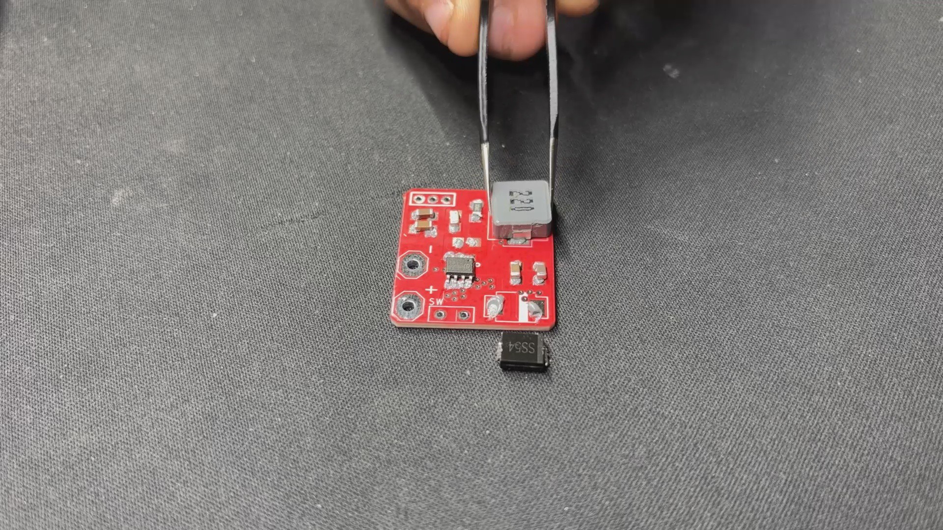
We begin the power board assembly process by adding solder paste to each component pad.
Next, we use an ESD Tweezer to pick and place each component in its proper location.
We lay the circuit on our Miniware Relflow hotplate, which heats the PCB from below to the solderpaste melting temperature, allowing all components to be soldered to their corresponding pads.
2
Batocera Box Design
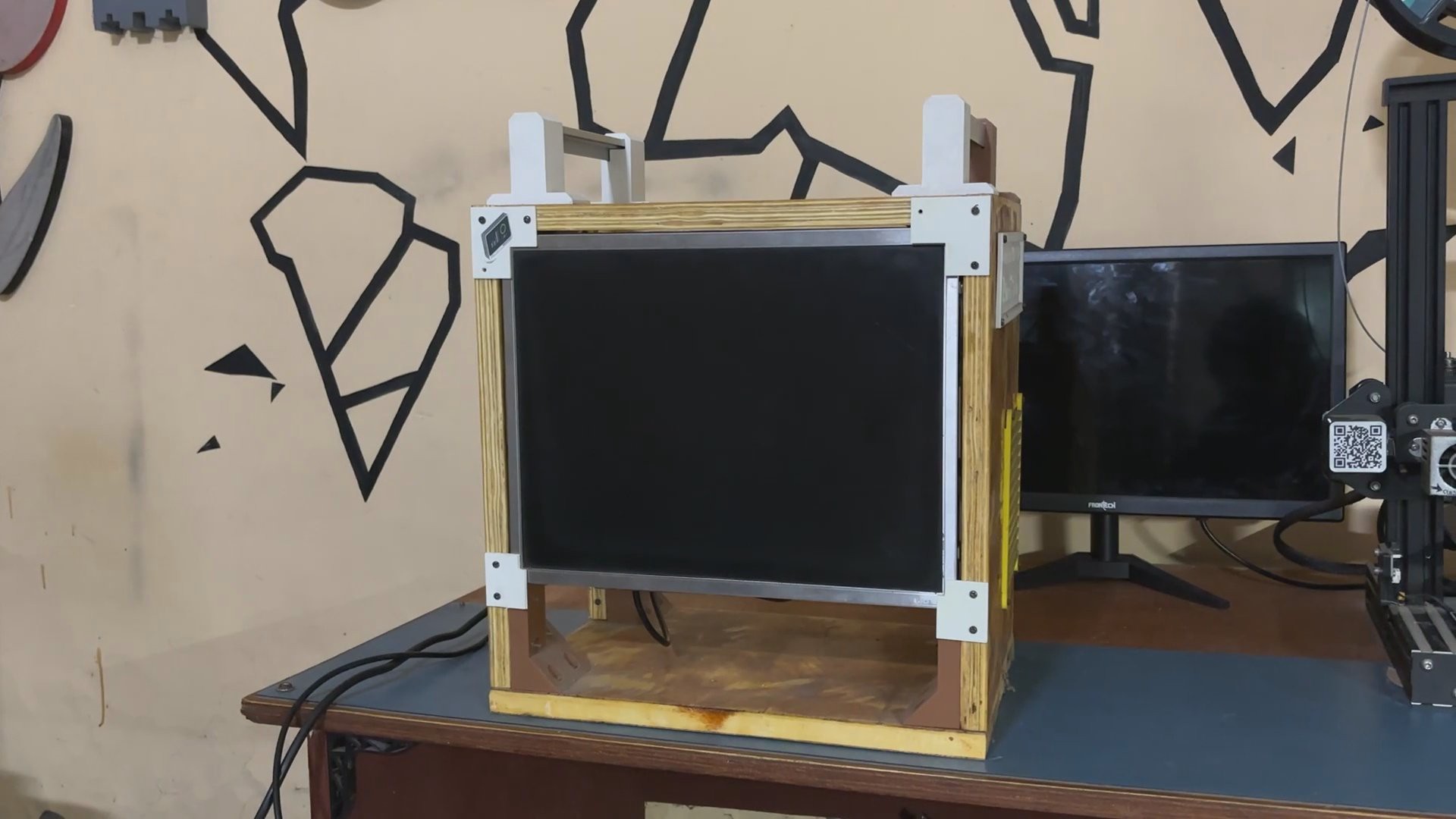
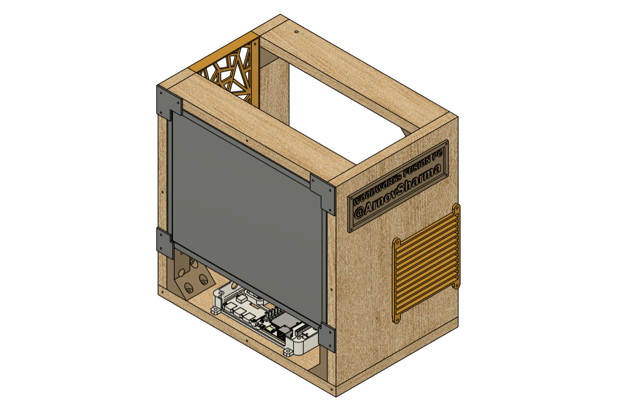
For this project, we are using one of our previous projects, the wood work fusion PC, which was an all-in-one PC made from wooden boards joined together using 3D printed brackets and featured a 15-inch LCD monitor as well as a motherboard, PSU, HDD, and all other PC components all packed inside the wooden frame.
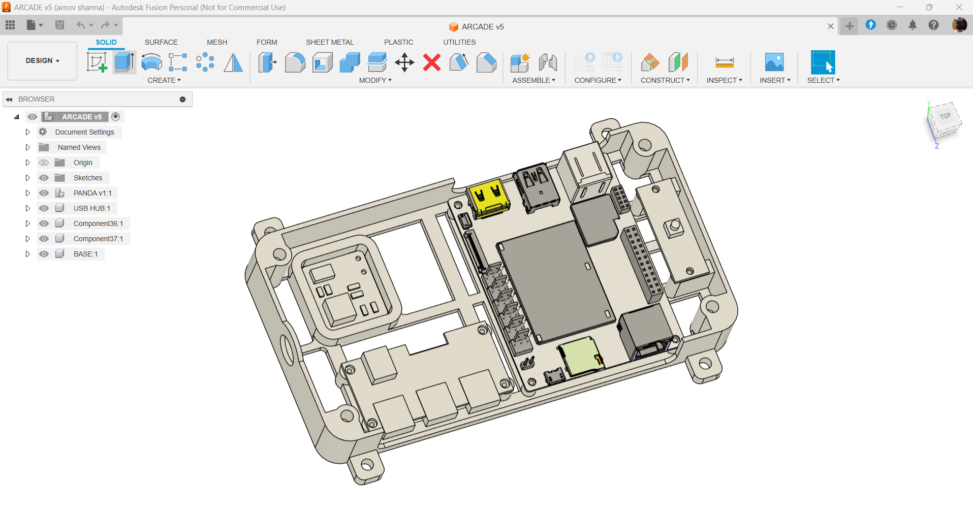
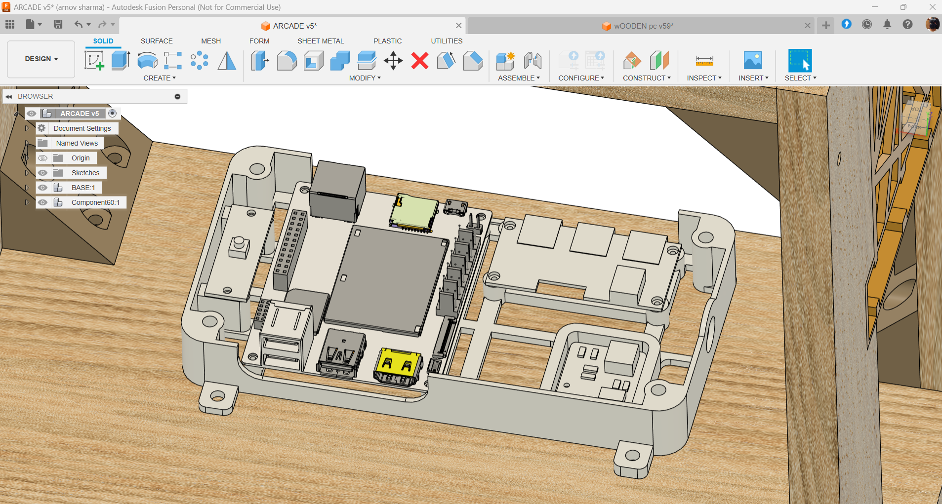
We wanted to use the PC's frame as well as the display, so we removed everything and began our design process by placing the Latte Panda v1 inside the wooden PC right below the display, along with the Model of USB Extension, and mounting them all on a customized frame body that holds the Latte Panda and USB extension in place.
We made four mounting holes in the frame so that we could use M4 wood screws to attach the frame to the wooden board.
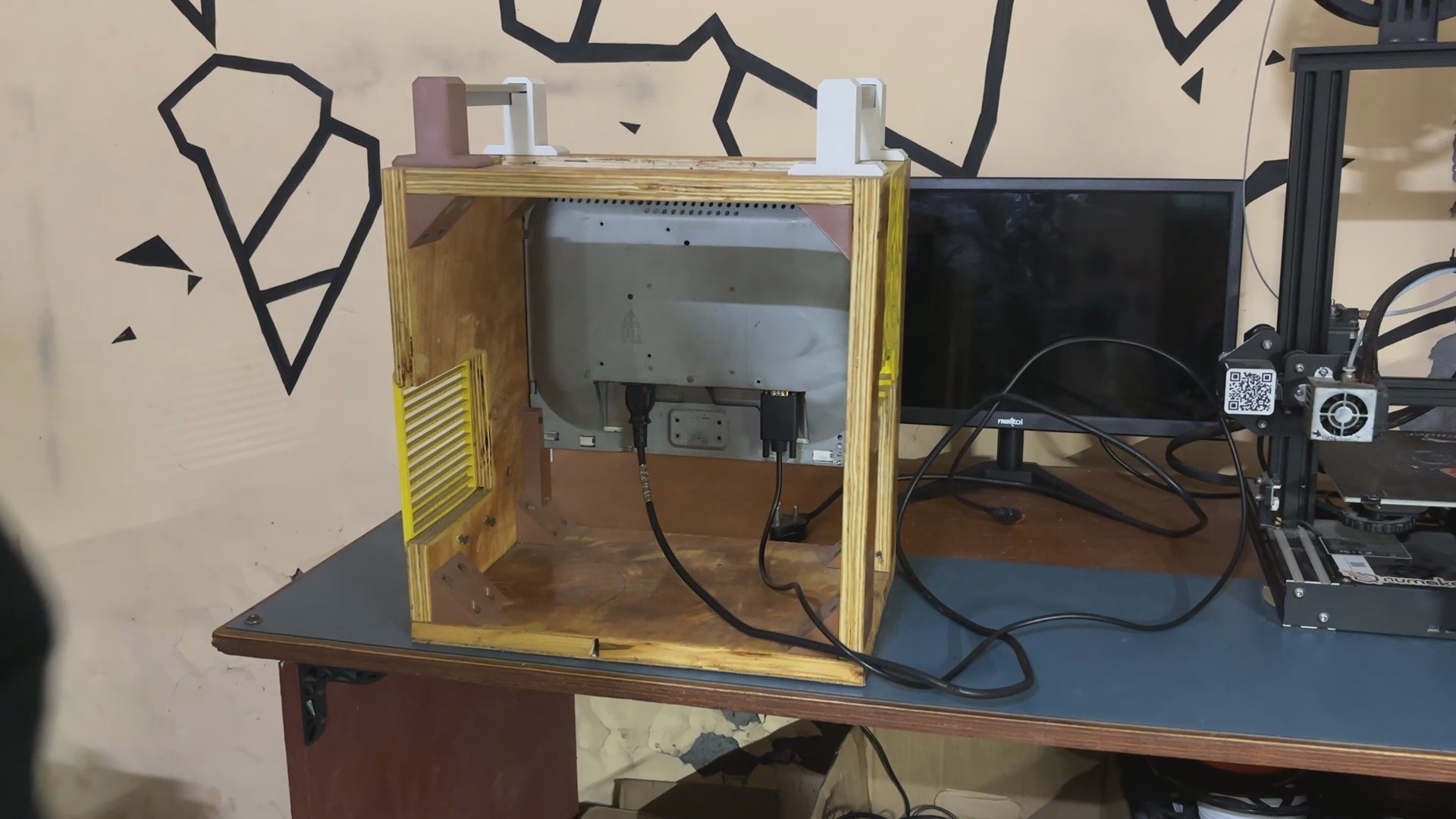
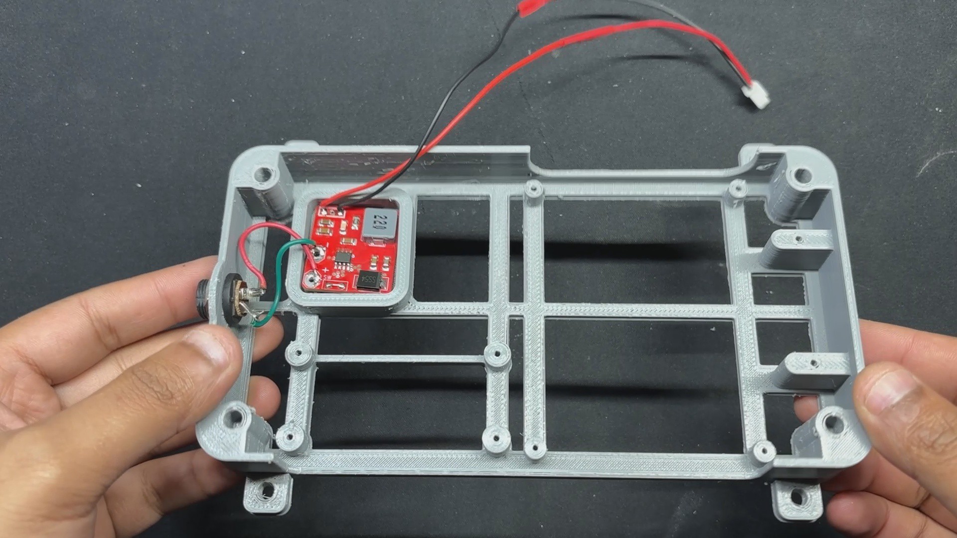
On one side of the frame, we installed a hole for the DC barrel jack, which is linked to the power board and will be used to power the Latte Panda v1.
Also, because it was difficult to reach the latte panda's power push button once it was installed, we added a switch board that we imported from another previously created project and placed it near the latte panda. This switch will be wired to the Latte Panda power switch and will be used to turn the device on and off.
After finalizing the model, we exported its mesh file, which was then 3D printed using Grey PLA with a 0.5mm nozzle and 0.2mm layer height, with a 25% infill.
3
Batocrea Box Assembly: Adding the Power Module and Latte Panda V1
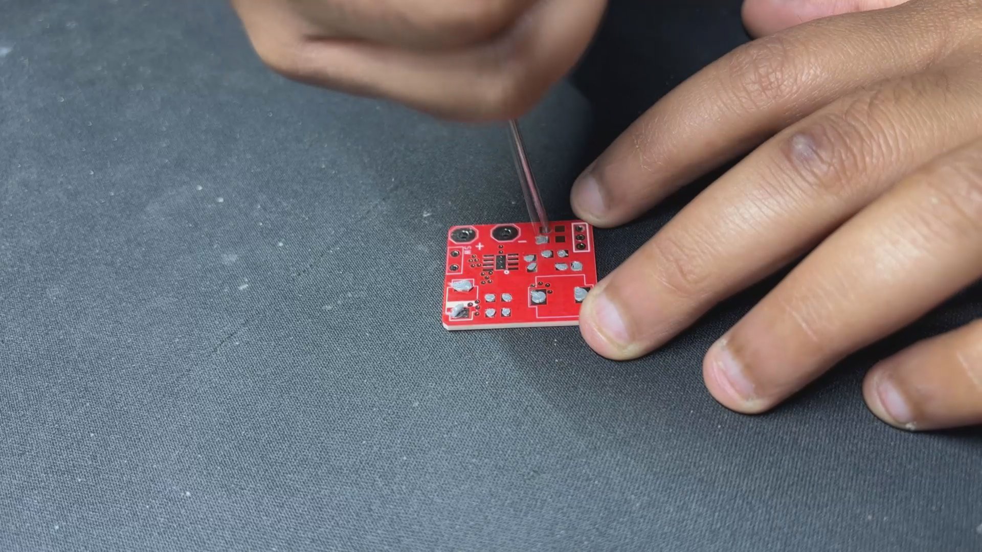
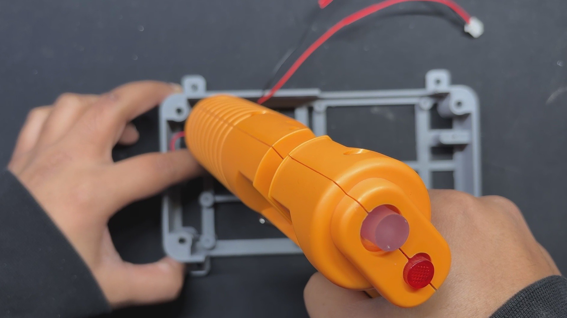
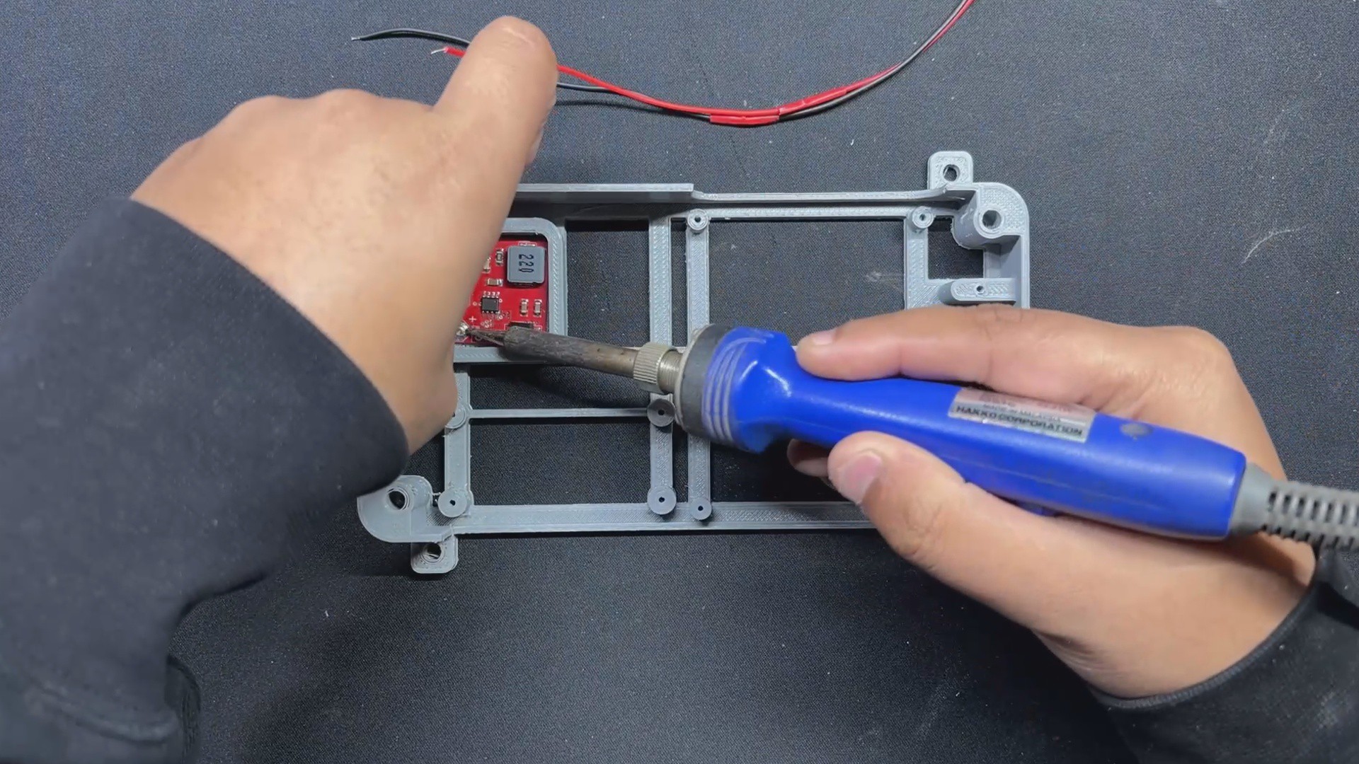
The assembly process begins with putting the DC barrel jack in its mounting hole and tightening it with the included nut.
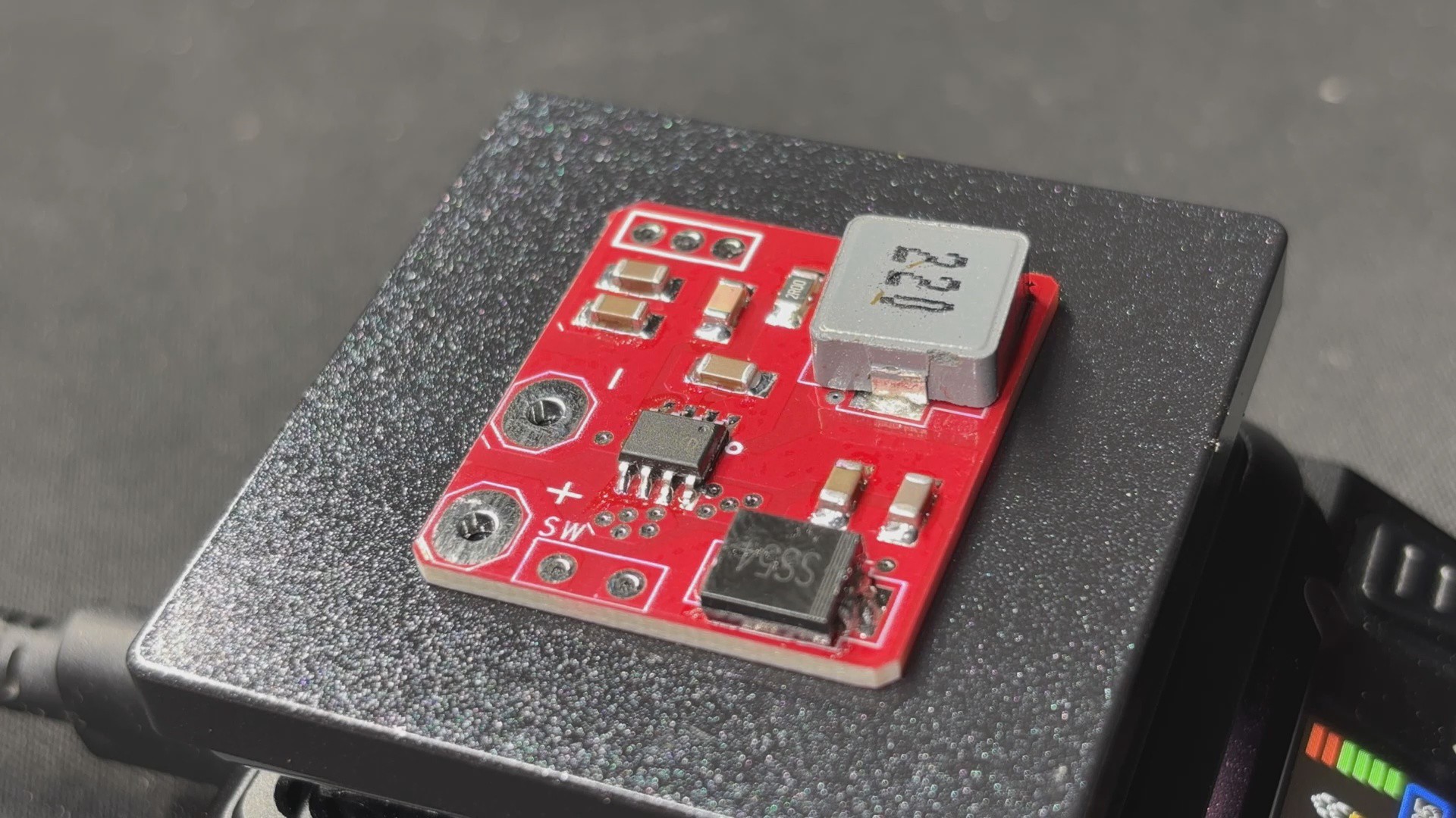
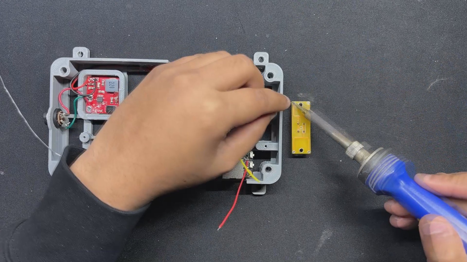
Next, we position the power module in its proper location and solder the DC barrel jack's positive wire to the Vin of the power module, connecting GND to GND.
In addition, we attach a JST UC2512 wire harness to the Power module's output positive and negative terminals; this wire harness will be used to power Lattepanda V1.
To permanently put the power module in place, we use a little amount of hot glue to secure it to the frame body.
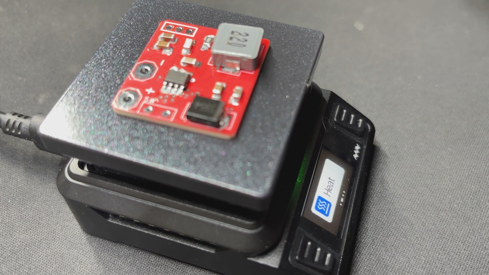
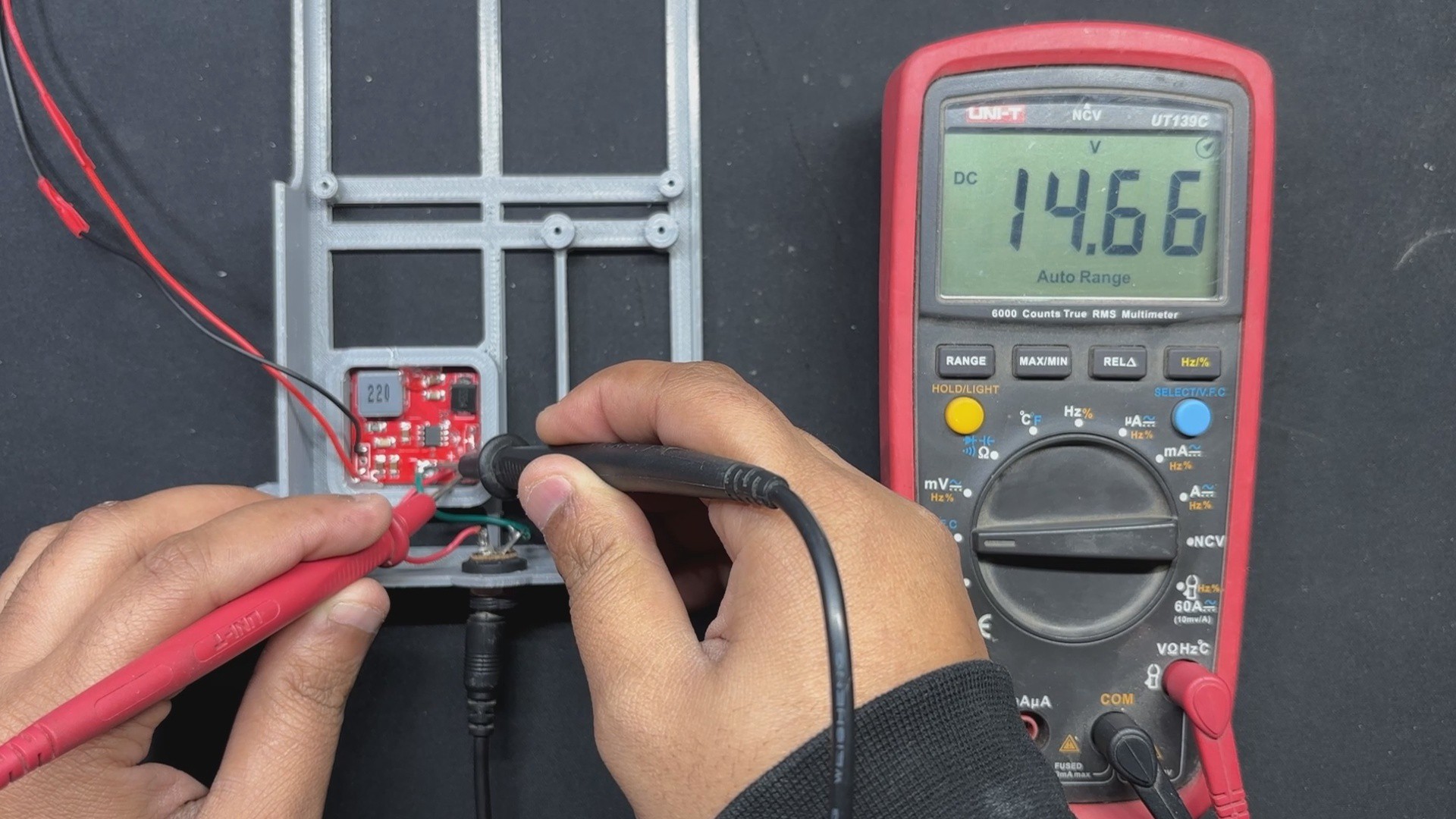
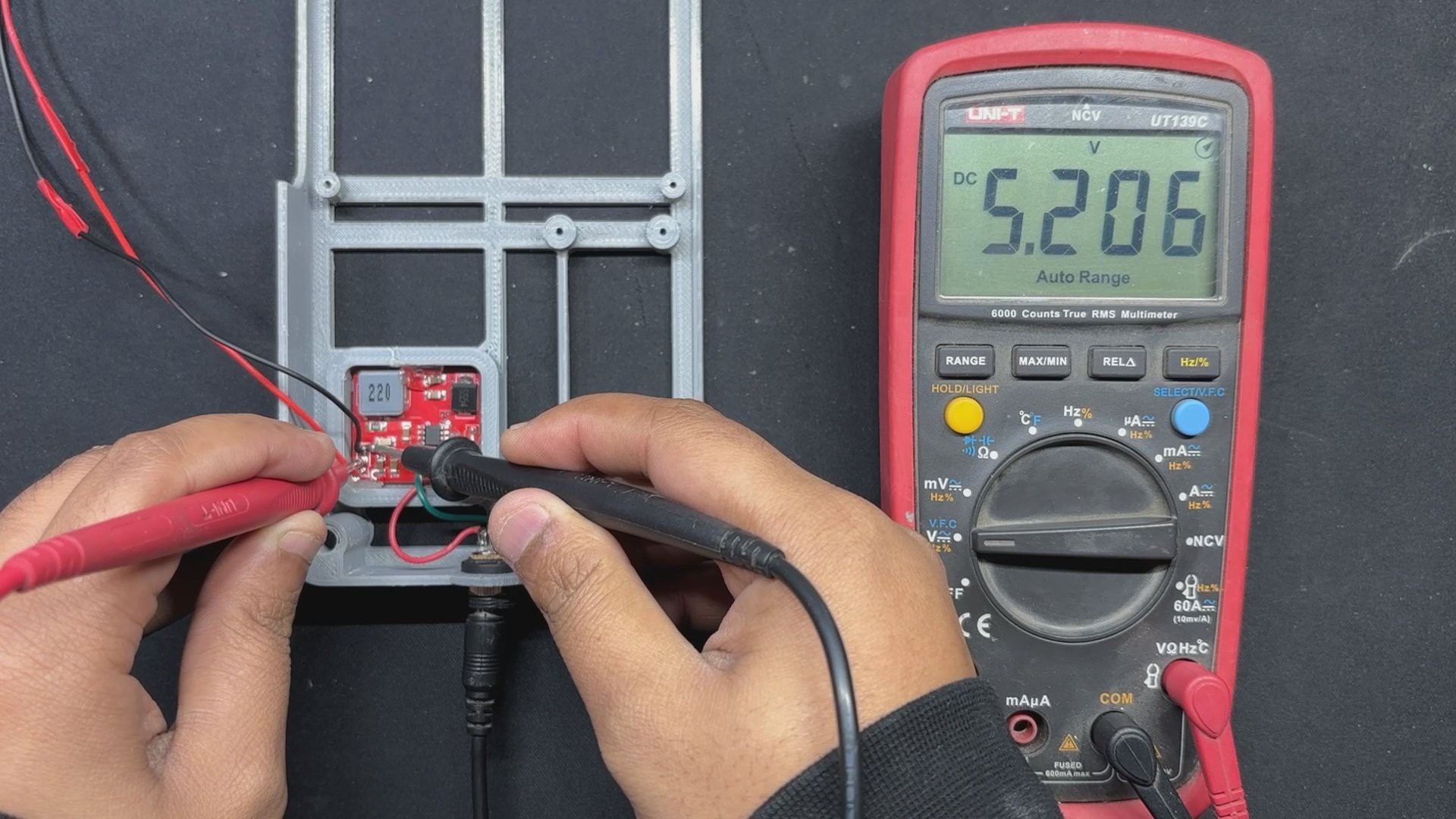
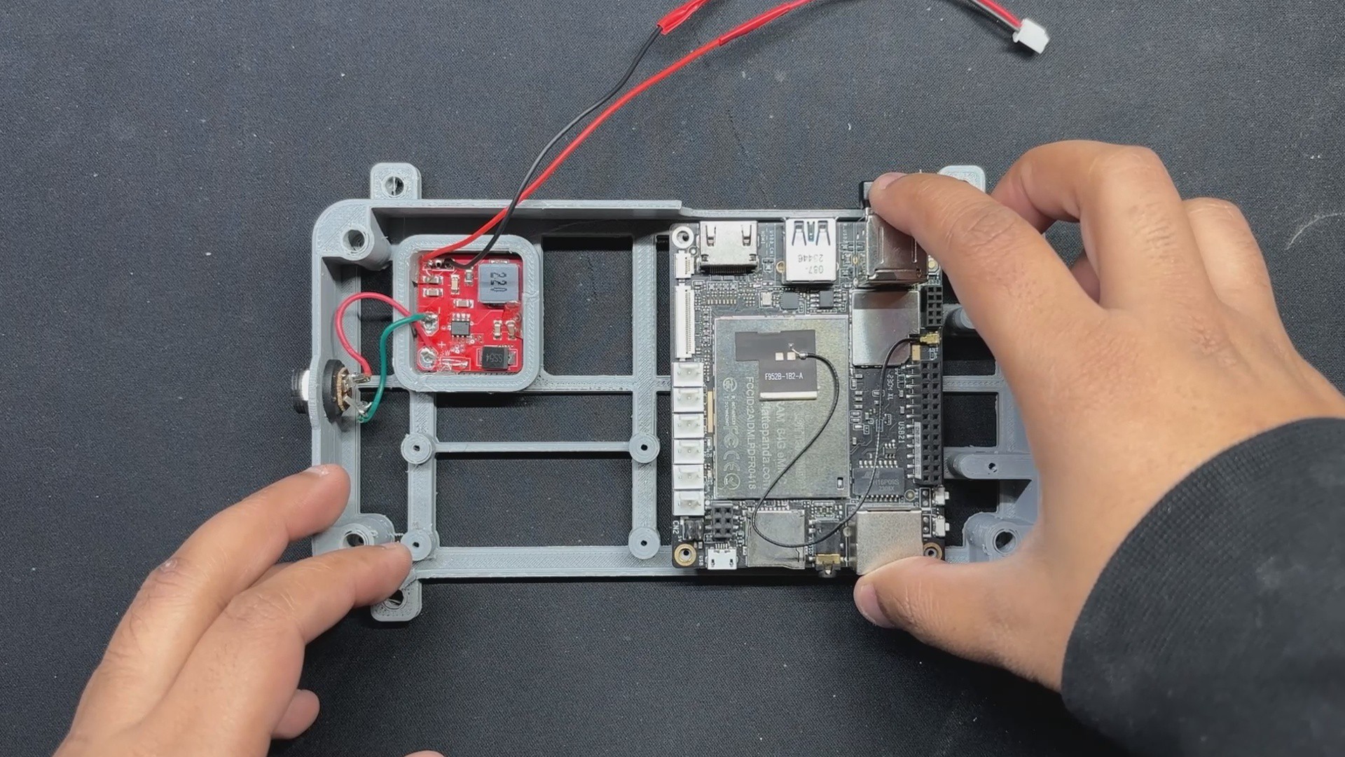
To see if our power module was working or not, we connected the 12V adaptor to the DC barrel jack and tested the output and input voltages; the input voltage was 14.66V and the output voltage was 5V, indicating that our setup was working.
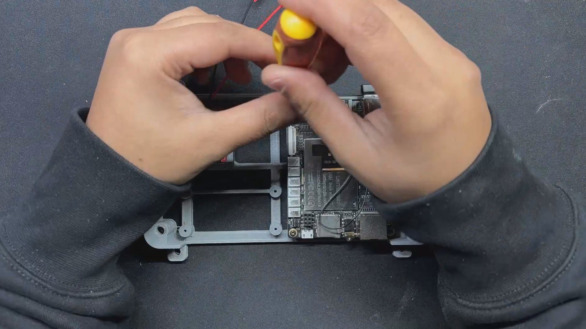
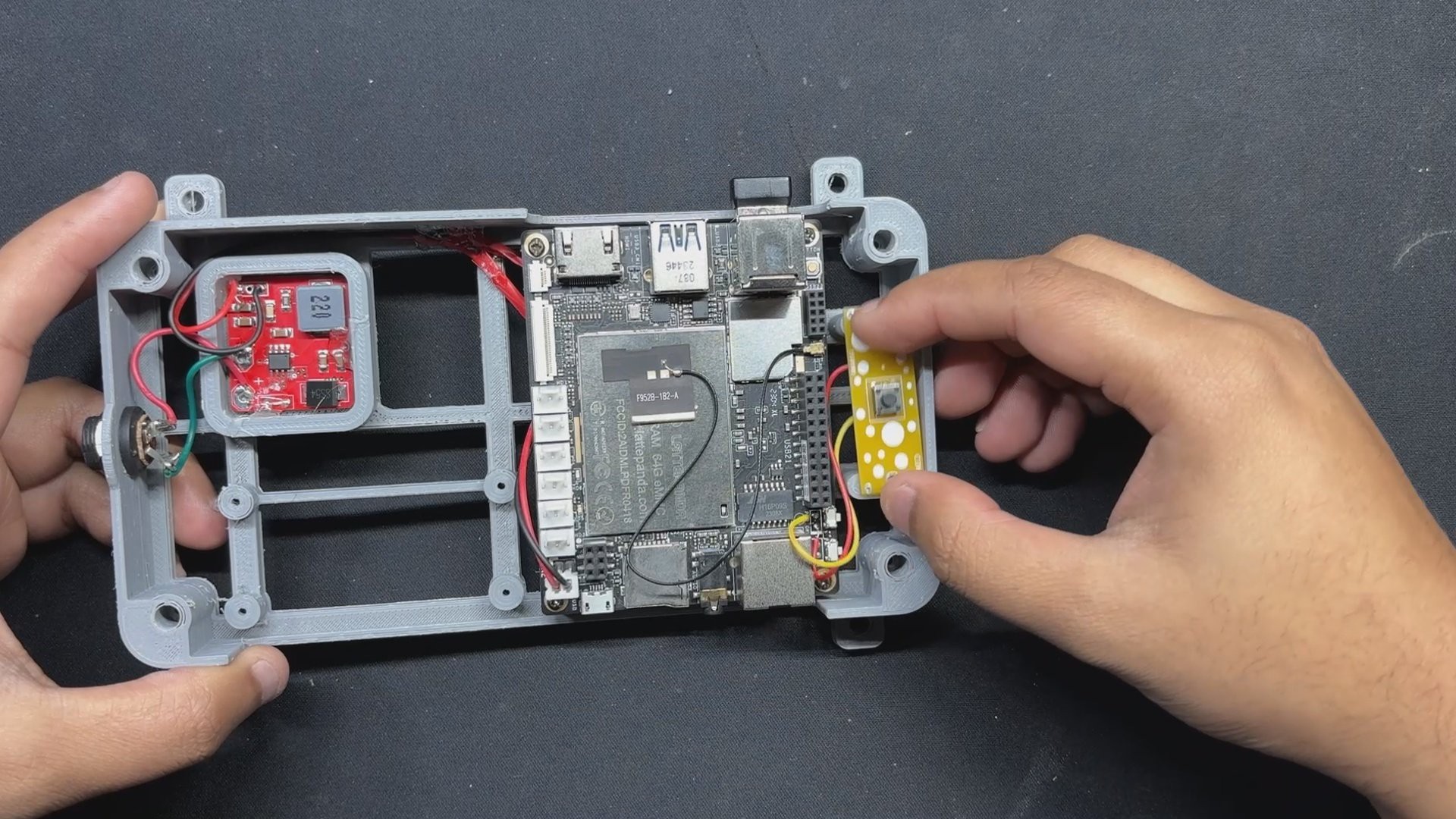
We now install the Latte Panda and secure it with four M2 screws.
Finally, the harness is connected to the Lattepanda's 5V and GND connectors, which can be found near the USB Micro port of the Lattepanda.
4
Batocera Box Assembly: Power Switch
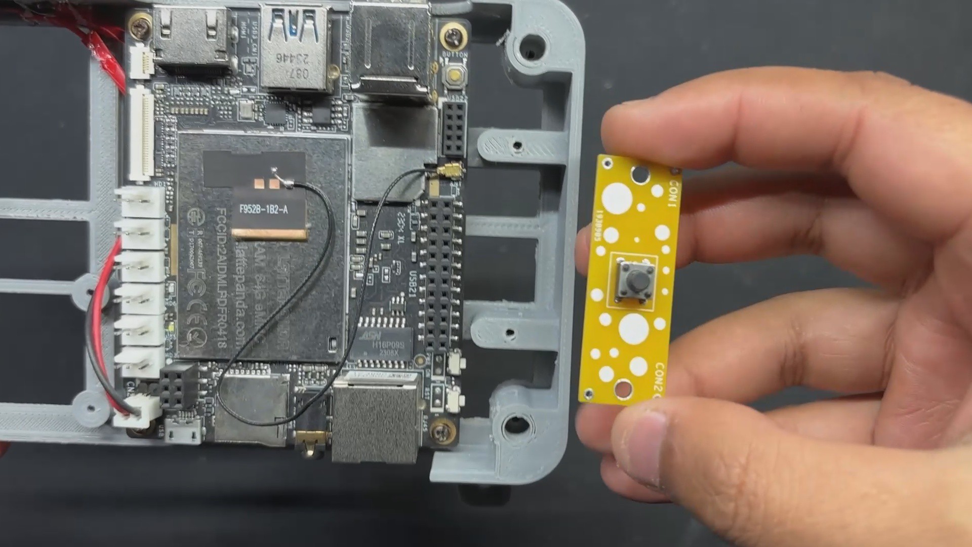
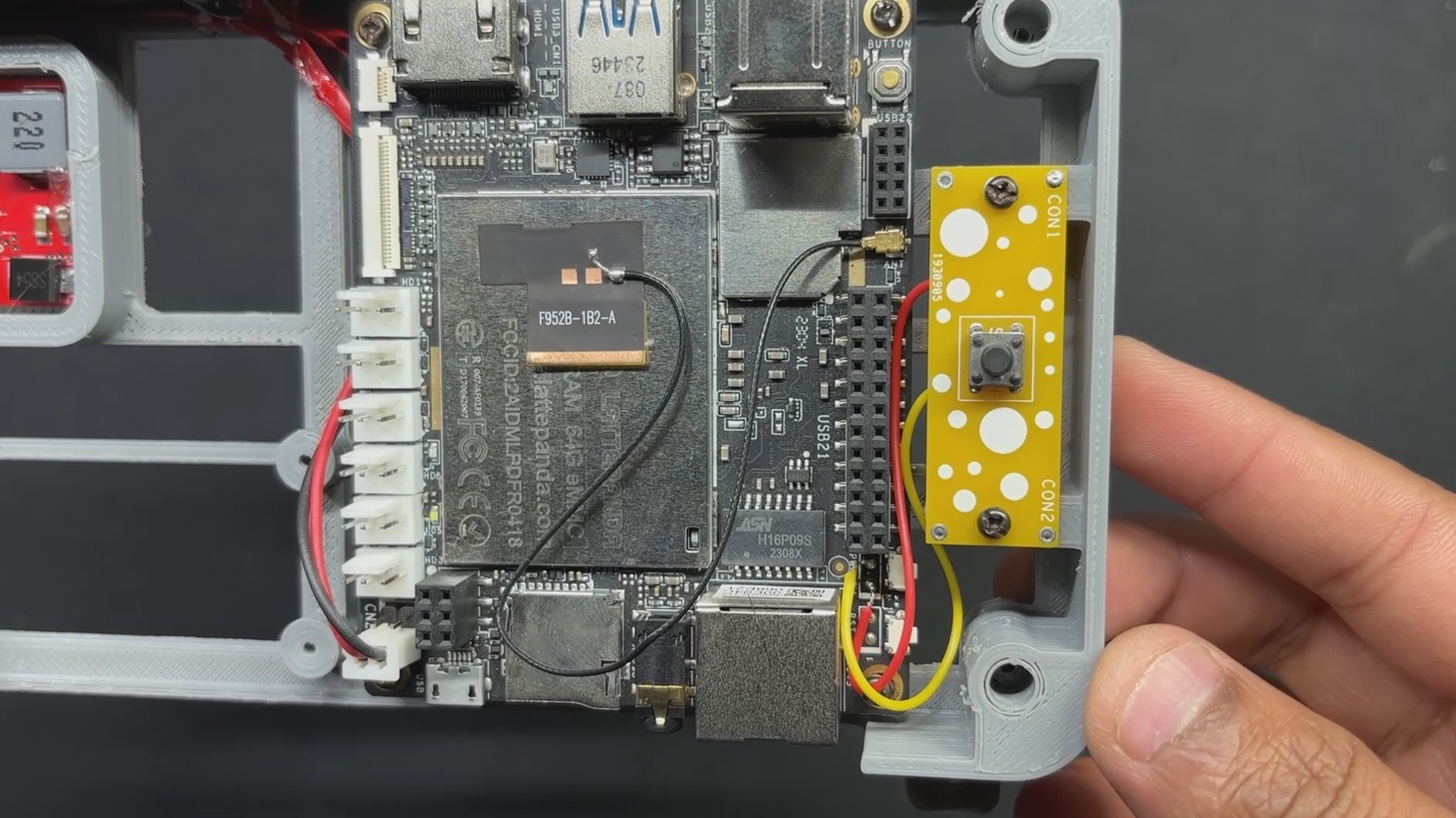
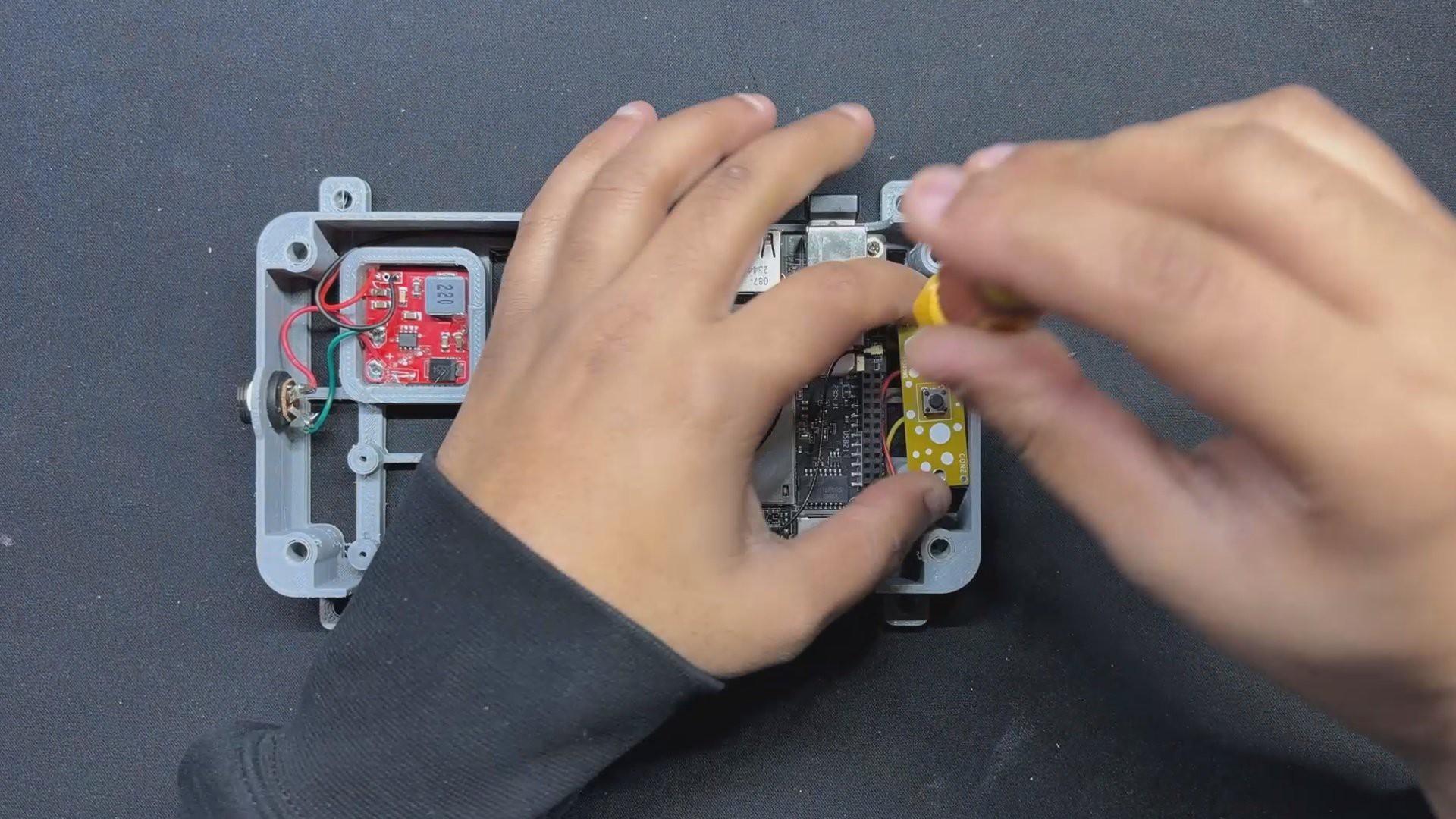
As mentioned earlier in the design process, because the latte panda v1 is mounted in the frame body, it is extremely difficult to reach the panda's tiny push buttons. To address this issue, we added an external switch that will be connected to the CON2 connectors seen behind the latte panda's push buttons.
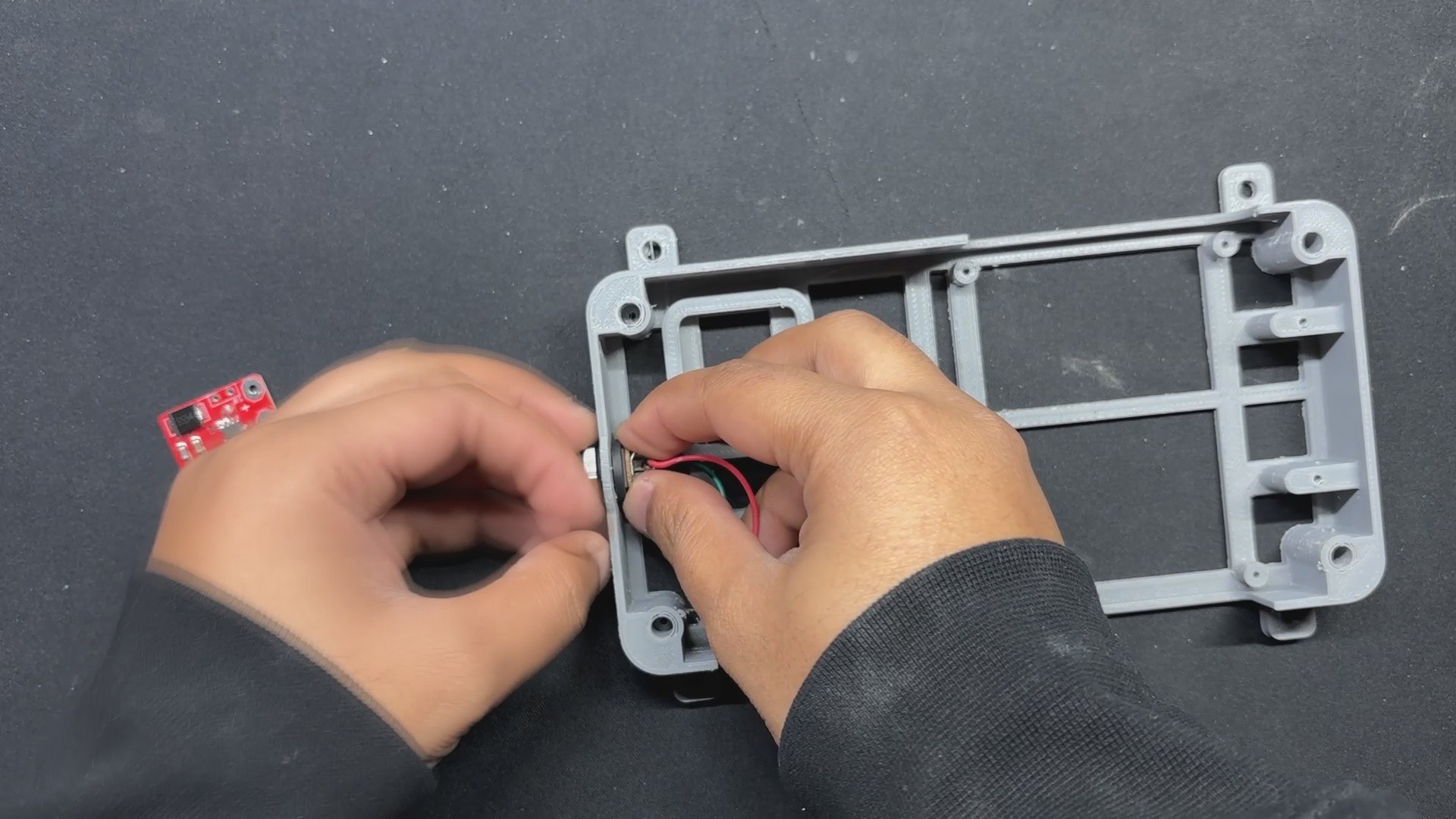
We begin by attaching wires to the Latte Panda's CON2 and linking them with the Switch Board's NO and NC terminals.
We next place the Switch Board over the screw bosses and secure it in place with two M2 screws.
5
Batocrea Box Final Assembly
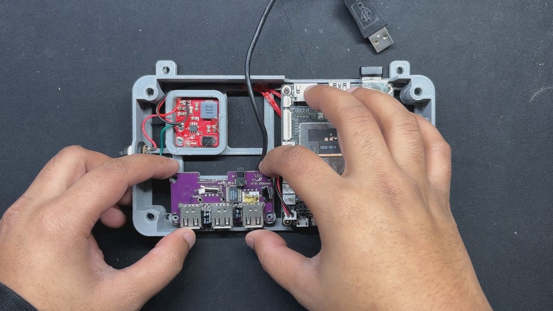
Finally, we place the UBS Extension board within the frame and use four M2 screws to secure it in place.
To test the arrangement one more time, we plug the 12V 4A DC adaptor into our DC barrel connector, which is attached to the power module; this causes the Latte Panda Blue status LED to light up, indicating that the setup is functioning.
6
Combining the Woodwork Fusion PC with Batocera Box
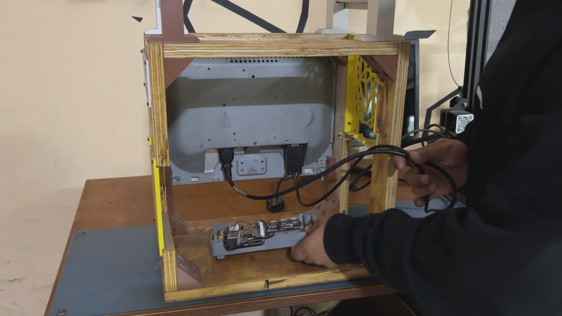
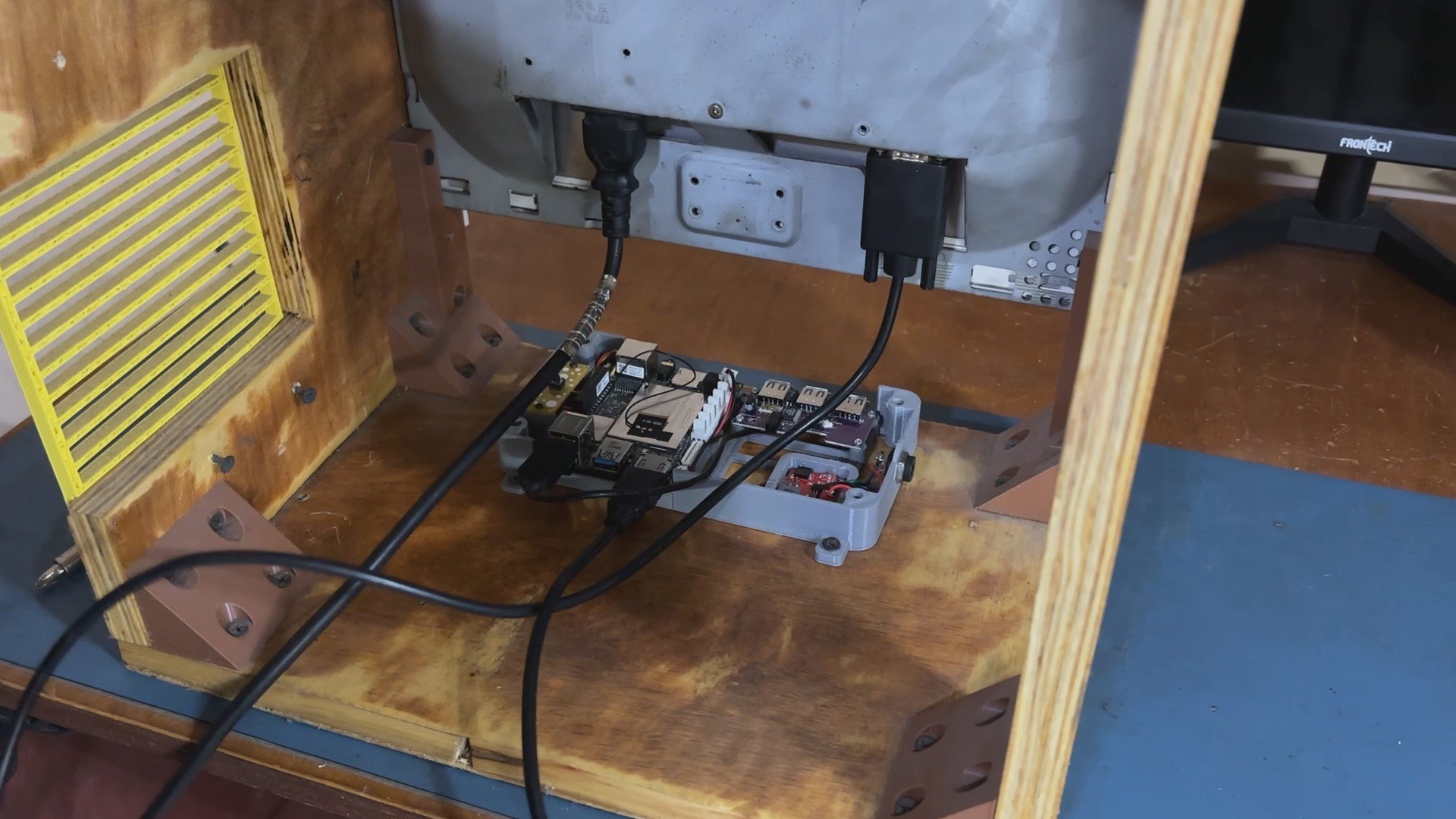
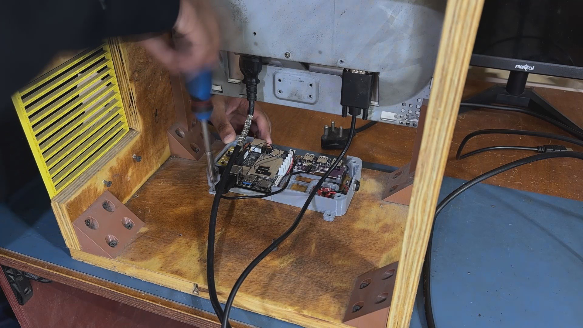
We install the arcade box inside the Woodwork PC, just below the display, and then use four M4 wood screws to permanently fasten the arcade box to the wooden base board.
Because we are utilizing an OLD LCD display with no HDMI output, we utilize a VGA to HDMI cable to link the display to our Latte Panda v1.
Two AC outlets will be used here, one for the display and one for the 12V adaptor.
7
Setting up Batocera and Adding games
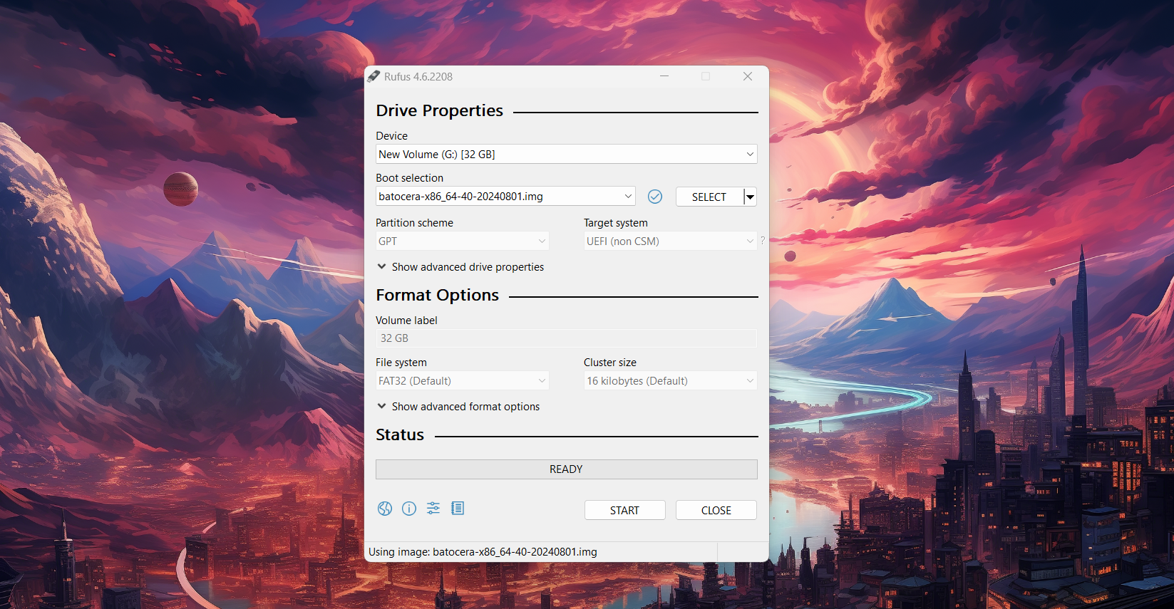
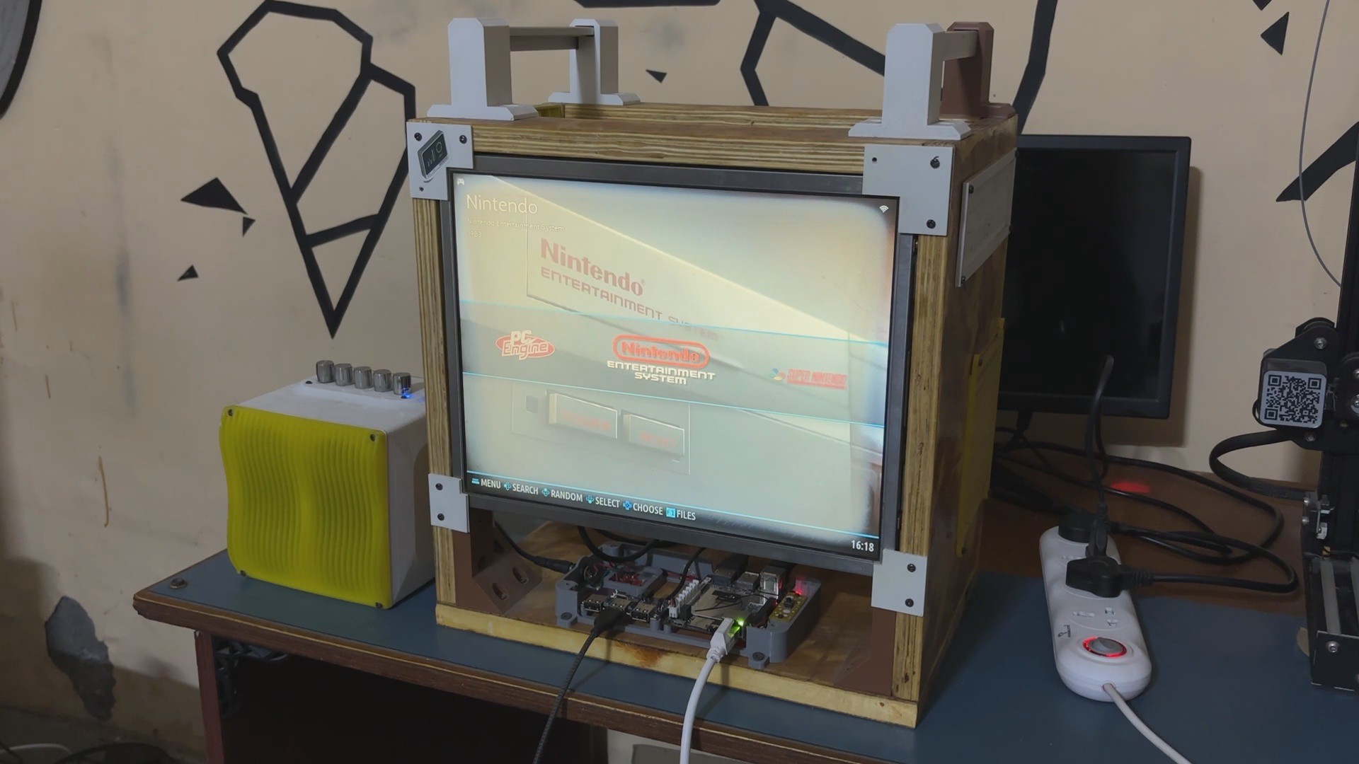
The project's star is Batocrea Linux, an opensource Retro Emulation Station OS that can be used to transform any computer into a retro arcade in a matter of minutes.
We downloaded the Batocrea Image file for our desktop PC and then used Rufus to create a bootable disk using the downloaded OS.
The OS installation process was rather straightforward; we plugged the USB Drive into the Lattepanda and turned on the device using the power adaptor.
We access the BIOS menu by pressing F12 and modify the boot order to boot from the USB drive first, then save and exit the BIOS.
We finished the process by following the on-screen instructions, and our OS was installed.
After installing the OS, we connected the Ethernet cable to our device, launched File Explorer, and entered \\batocrea in the address bar to access the shared files on batocera.
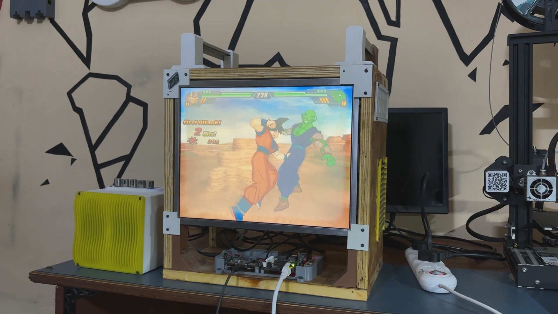
We open the rom files on the batocera's shared drive and copy the ROMs into the emulator directories. For example, we put the Roadrash ROM in the PSX folder and the Budoikai Tenkachi ROM in the PS2 subdirectory.
After copying the ROM, we restarted the device and proceeded to game settings, where we picked update gamelist, which made all of the games added visible on the Batocera game menu.
8
Result and Overall Conclusion
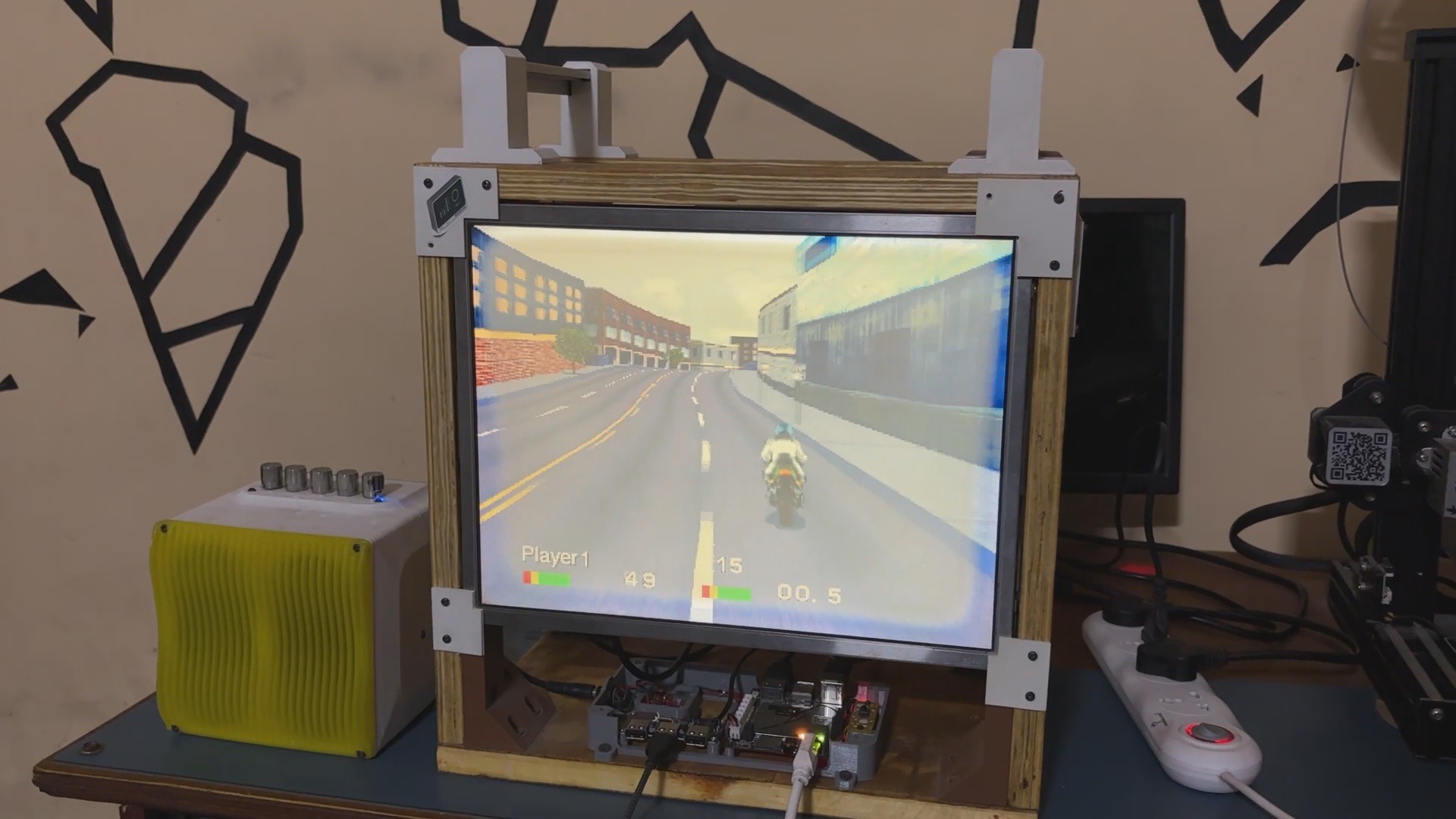
Here's the end result of this small build, an Arcad machine Running Batocera.
We ran the OG Roadrash on the batocera using the PS1 emulator and our XBOX controller to control the device; for some reason, we were unable to connect our Xbox controller over Bluetooth, but the Bluetooth speaker worked well.
Using Arcade, I was able to show my younger sibling the games I used to play when I was younger, such as Roadrash on my Windows 98 PC, NFS1, old Dragon Ball Z games, and others.
In terms of constraints, the Budoikai tenkachi that we attempted to run on the PS2 emulator had a frame rate issue; it was working but at a very low framerate, which might be due to poor batocera optimization on the SBC we were using, or our Latte panda v1 was simply not powerful enough.
This Arcade Machine is fantastic for arranging old-school gaming nights; we can connect many controllers and have a great time, much like we did in the early 2000s, which was one of the reasons for creating this setup.
Emulation can be performed on any newer PC with a better graphics card, so why did we create a completely new setup with a lower-powered SBC? The rationale for this is that, while modern technology allows for greater simulation, creating a sbc-based arcade system with an old broken LCD display evokes the feelings of nostalgia. I wanted to utilize a CRT monitor in this project but couldn't locate one that was the right size, but that may be addressed in a future version.
This project went well overall, and I'll be back with version 2 shortly, in which we'll upgrade the device and utilize a much more capable SBC with a graphics card for emulation.
 Arnov Sharma
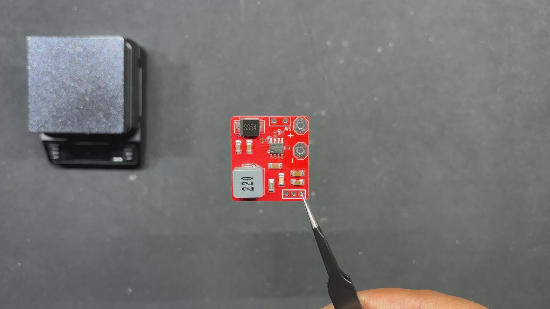


Discussions
Become a Hackaday.io Member
Create an account to leave a comment. Already have an account? Log In.