Oliver Scholz
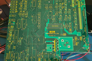
This mainboard drops into both US as well as European ColecoVision cases. You can use the original shielding, but be careful it doesn’t scratch the board and shorts out traces. It may make sense to stick some Kapton tape on the PCB or shielding for protection. Also, depending on which options you choose to build, you may have to add holes to the shield and/or case!
Yes, options! There are many. You can build a basic ColecoVision (CV) with a Composite output, play games and be happy.
But this board was made for experimenting, and a few things are different from a vintage CV. Let me ramble:
Power supply. The CV power supply provided three voltages and was prone to breaking. And the Coleco power switch only switched two of the voltages, so one was always on! So, the board is powered by a single 12V supply with a standard barrel connector. Instead of soldering the connector to the PCB you can use two wires and add a barrel connector with a 3D printed plate at the opening for the stock Coleco power supply jack. So instead of the heavy brick you can use a standard 12V wall wart from Radio Shack. Ok, they’re gone, but you know what I mean. Bonus: the 5V supply for the CV is a 90% efficiency switched power supply, and it’s controlled by a voltage, so the current doesn’t flow through the power switch. This means that most CV power switches can be used on this board, even if one side is broken!
Memory. The CV featured 1K RAM and an 8K BIOS. Since mapping is controlled by a GAL and the unit features 128K RAM plus 128 ROM, various memory maps can be implemented, and since the board has an additional memory mapping register, a lot of stuff can be implemented, like built in games, development support, etc.
Sound. The CV was somewhat limited in that respect, so Coleco planned to add, but never released, a super game module with an AY 3-8910 sound chip. This board has a socket for that sound chip, so going from 3 to 6 voices is a matter of plugging in an AY chip or alternatively a compatible Yamaha chip. As a bonus, the three extra channels use a stereo matrix so you get a left, center and right channel. And an optional stereo/mono switch. Oh, and the AY chip comes with two 8 bit ports that can be used for - anything!
Speech synthesis. I have designed a piggyback board with a SP0256-AL2 voice chip. Available at Radio Shack. Oh well.
Video. Oh, the choices. You can use a TMS video display processor (VDP), and since vintage dynamic RAM is kinda hard to get, a modern static RAM is used. There are three VDP choices:
- TMS9918, which produces composite video @ 60Hz and is cheap. Video goes to three Chinch jacks.
- TMS9928, which produces component video @60 Hz, so picture is better
- TMS9929, which produces component video @50 Hz for European users
The two latter choices require the installation of TMSRGB components, yielding crystal clear RGB video on a Sega compatible MiniDIN connector with stereo audio.
But, you can go a completely different route and install a Pico9918. Then you can eliminate a bunch of components, like video RAM and latches and video clock. The board has provisions for a FFC connector going to a VGA jack on the mainboard, and a second FFC going to the MiniDIN, for details see Pico9918 documentation.
Pause. Using a separate ATtiny processor, the reset key can be used to reset (duh), pause or slow down the processor. Lots of opportunities right there!
USB. The board features a USB port, so using an appropriate bootloader you can use it to emulate an ADAM SuperDrive, download games from a PC or access the internet.
Configurations and Sega compatibility. The board is equipped with two dip switches connected to the address and IO mappers. These can be used to map either CV peripherals and memories or map them to their locations on a Sega SG1000. Or other similar Z80 based systems. Just burn a Sega image to a CV cartridge PCB and run it. And you can have two sets of BIOSes for each platform. Only one Sega joystick...
Read more »


 Dave
Dave
 cyplesma
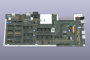
 SukkoPera