Close
0%
0%

Analog Sim Handbrake

A sim racing handbrake based mostly around an Ender 3 Pro X Gantry, an Adafruit TLV493D, and a pro micro

Similar projects worth following
254 views
0 followers
Homemade sim racing handbrake based on parts taken from an Ender 3 Pro, with a bulk of the parts coming from the X gantry assembly. The electronics used are an Adafruit TLB493D 3 axis magnetometer connected to a pro micro board.

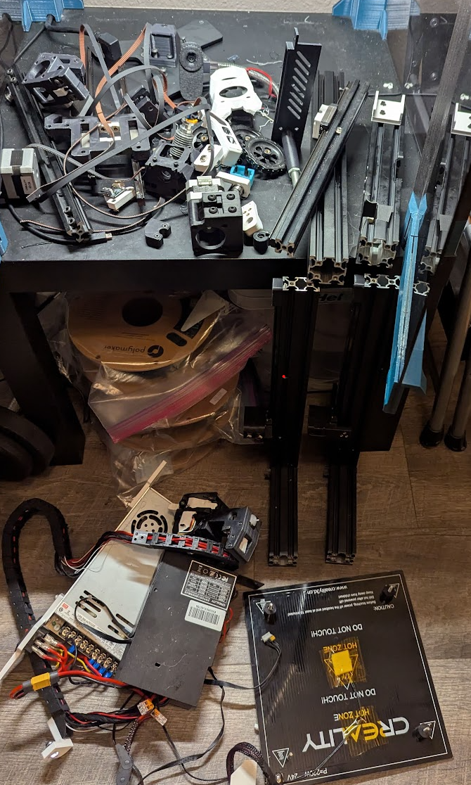
For a while I was wanting to buy a Logitech G29 wheel set. Naturally, I decided to spend alot of money on a Fanatec CSL DD combo instead so I wanted to make a handbrake out of stuff I have lying around my house. I hoard alot of random parts so with some digging around and some 3D printed supporting parts, this came out to be essentially a "free" project for me. It wasn't really free because I bought all this stuff at one point but I managed to avoid buying any additional parts.

Rather than a DIY project, this is more of a DIM project (do it MYself), simply because it would not be worth it for someone to go out and buy all the parts just to make this. If you think about it, this is just a giant 1 axis joystick made out of garbage. I do hope this project can serve as inspiration for people trying to make their own sim racing peripherals. If you are looking for a tutorial type project, there are better performing and likely cheaper options out there. 

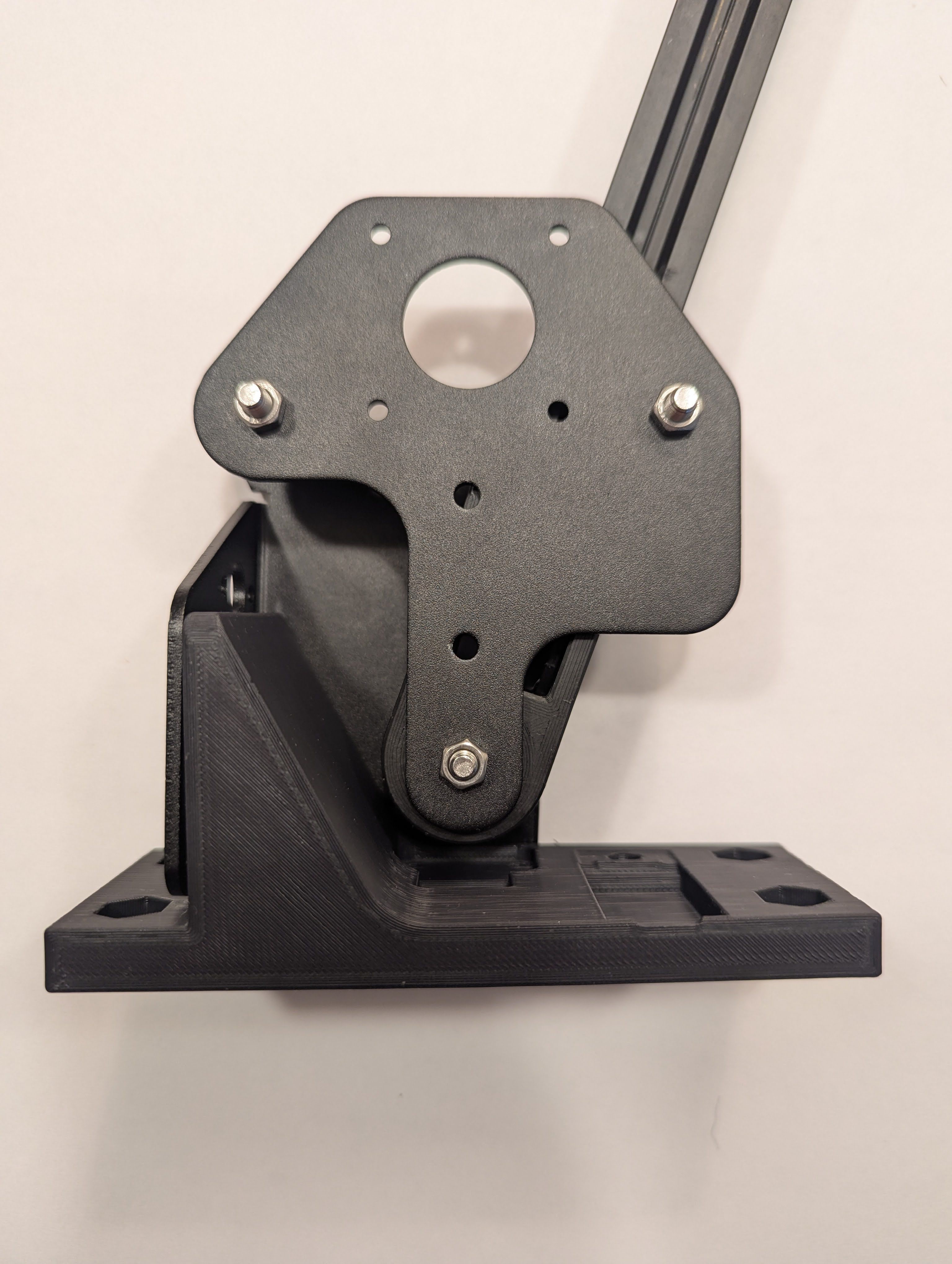
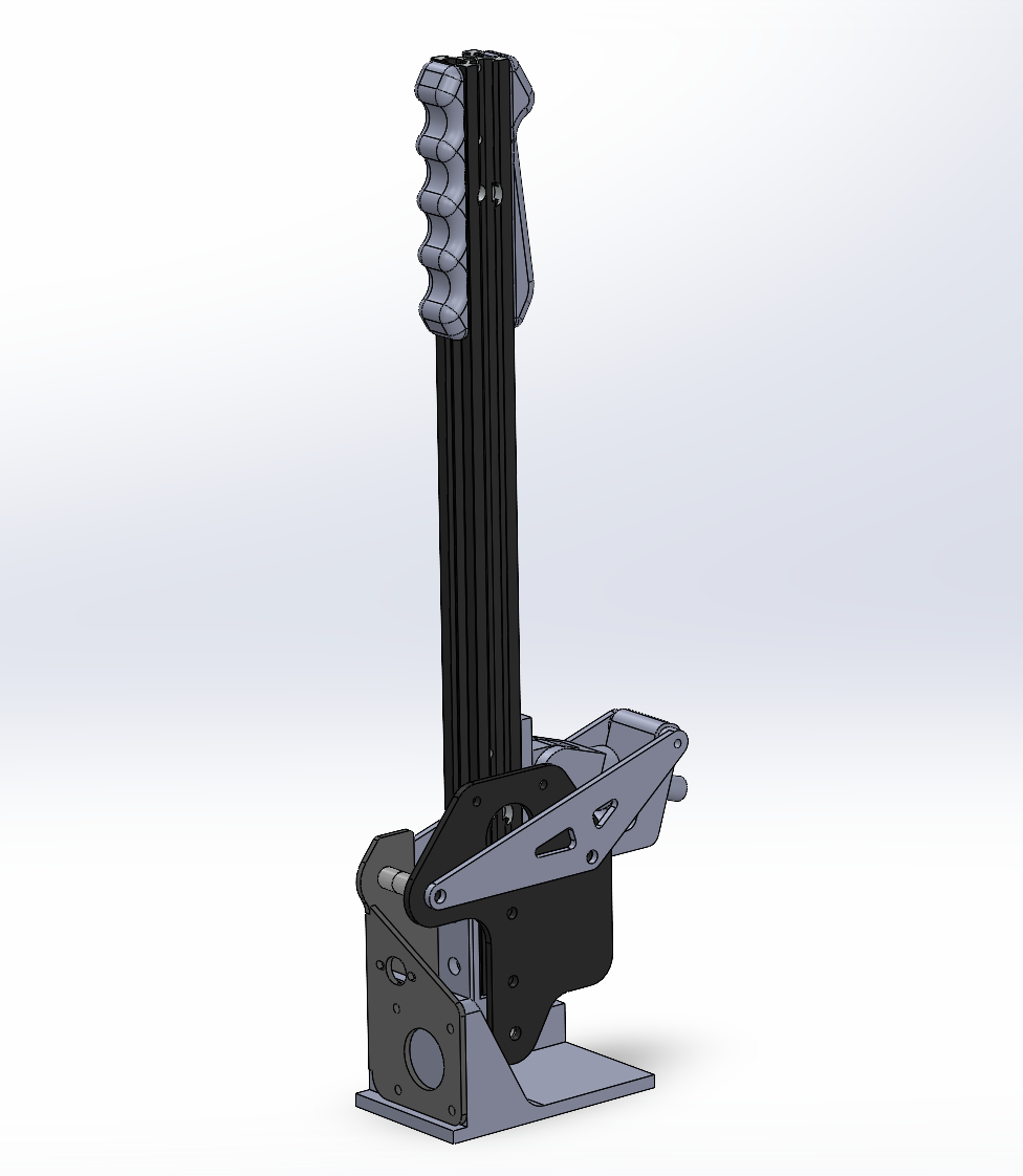
I think a fully 3d printed (or machined) project would be much cleaner, but the constraints of having to incorporate off the shelf brackets and parts makes the design process more fun.

I hope to keep this project on going for now because even though the first iteration works, there is always room for improvement. 

  • 1 × poo Interconnect Products, Wire and Cable / Misc. Interconnect, Wire and Cable Products
  • 1 × pee Electronic Components / Misc. Electronic Components

  • 6: V0.9 Finished

    cmoon551101/24/2025 at 00:09 0 comments

    I want to refrain from calling it V1 yet as it's still all PLA, but I am definitely going to be using it until things start breaking. It felt good replacing all my future tense with past tense in the project description. Although everything technically works, there are a few issues that should be solved. For one, the pro micro usb port is way too close to my shifter when mounted. I got all the wires nicely cut and routed so I really don't want to move the pro micro but I will probably need to unless I get ahold of a right angle micro usb plug. Or a left angle one since I don't remember how the naming convention works. My main concern is getting the solder out of the through holes, since I destroyed my desoldering pump. 

    Another Issue is the way the pivot assembly all goes together. There is no good method to adjust and tighten the pivoting plunger arm assembly.in a user friendly way. Basically I have to dry fit the assembly to make sure the plunger is at the correct angle, disassemble it to tighten the screws, and then reassemble it. There is also a decent amount of flex if you pull too hard, which might be unsolvable without making everything super thick. 

    I was trying to put a BOM together but I don't think anyone sells an entire replacement x gantry, or even the brackets I used. If you're up for a double project, you could try scooping up a Facebook marketplace special ender 3 and then convert the original gantry to linear rail (don't actually do this). If you would like a list of parts anyway let me know. I also don't have an intuitive way of recording gameplay along with recording video of the actual handbrake in action, but I could try figure that out as well if anyone wants.

    Full disclaimer about the code; I used AI to help me initialize the magnetometer and joystick and map the sensor values to joystick values. I think I could have eventually figured it out in a few hours to days by reading through forum posts and documentation, but the AI generated code had me up and running in less than half an hour. I did have to debug and tailor the code for my specific use case, but for someone who opens up VSCode maybe once a quarter it was a huge help. The magnetometer itself was originally used for Salim Benbouziyane's DIY spacemouse project that I ended up not using much (https://www.instructables.com/DIY-Space-Mouse-for-Fusion-360-Using-Magnets/). I also adopted his idea of filtering the signal, and applying a calibration offset at startup. The idea to use the Joystick library was taken from AMStudio on youtube, specifically his project to convert a Logitech shifter to usb (https://amstudioprojects.com/shifters/). The shifter project was a main inspiration for this one, even though they share little in common besides being sim racing peripherals.

  • 5: Redesigns

    cmoon551101/23/2025 at 03:32 0 comments

    I did not do the things I set out to in the last log. I found a good spring inside a cheap spring loaded desoldering pump I had kicking around. I added some foam backer to the plunger stop to act as a sort of damper.  Some of the holes I left for heat set inserts are too close to edges to be usable. I will try getting this programmed before I start printing the final batch of parts. I also think I could make the grip a little bit wider.

  • 4.5: Printing

    cmoon551101/17/2025 at 23:14 0 comments

    I have begun printing parts out of PLA to dial in dimensions. I am hoping to have the final pieces printed out of ASA but I am known for using my prototype parts indefinitely until they fail. 

    This is a good time to remind myself to double check the accuracy of any 3D models found on the internet. The 4 main mounting holes for the ender brackets are in the completely wrong place, and the pro micro model I found was too small. The Ender 3 has gone through so many micro revisions though so I can only blame myself for that one.

    My wheel and pedals are expected to arrive in less than 24 hours. All I need to do is fit test everything with PLA before I go to bed, have the ASA prints run over night, and then code and wire the electronics tomorrow morning without anything going wrong. 

  • 4: Final Design

    cmoon551101/13/2025 at 21:15 0 comments

    The design is nearly finished, any last changes will probably be done once the initial print is put together. I am hoping to reuse some of the threaded holes on the extrusion for mounting the return spring. If that doesn't work I will have to come up with some sort of solution which shouldn't be too hard. 

    I need to wire up the components and start working on the code. Hopefully I can steal from other people's code used for similar projects I have made. 

  • 3: Even more design

    cmoon551101/09/2025 at 21:17 0 comments

    The mechanical design is now a bit more fleshed out. The compressive springs I have are too small to fit over the bolt I am using for the plunger, so I will need to rig up some way to use an extension spring. I am bad at making ergonomic things but I did my best to make some comfortable looking grips.

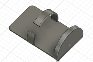
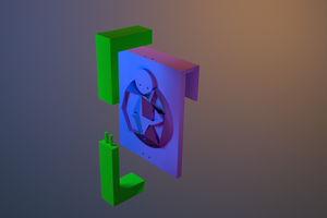
    Now I need to make a place for the magnet and all the electronic components. It would be cool to route the wires through the hole in the front of the base that is typically used by a motor shaft, but I'm not sure if there will be enough room.
    Cross section
    Cross section

    The bolt used as the plunger will be held into its pivot by a set screw. The bracket that the plunger works through is mounted to the frame by slipping over the spacers in the rear, and is braced by two side brackets. I am hoping a long 3mm bolt through the rear most mounting hole (top right of cross section) will provide more structural support than a continuous 3d printed part where the force might cause layers to shear apart at the sides. I will also need to thicken the handle pivot attachment to reduce any lateral movement of the handle during use.

    I need to tackle the least fun part of the project now which will be putting my 3d printer back together

  • 2. More Design

    cmoon551101/06/2025 at 18:04 0 comments

    Updated Handbrake Design
    Updated Handbrake Design

    After playing around in CAD, I decided to rotate the whole assembly, and flip the orientation of the extruder motor bracket. This eliminates offsetting the whole assembly like my initial design, and gets rid of some clearance issues I ran into with the handle pivot.

    Closeup View
    Closeup View

    The design change also allows for equal range of movement both forwards and backwards. There is now potential for this to be both a handbrake and sequential shifter, but that sort of thinking is way outside the project scope. I will just focus on the handbrake action now so this doesn't get added to the unfinished project shelf.

    After some consideration I will now be trying to use a 3 axis magnetometer rather than an analog stick. I have one lying around, and it sounds easier than trying to design a linkage mechanism for mating the handbrake to the analog stick.

    I found an old pair of no name skateboard trucks that uses a removable hex bolt as the kingpin which I will try to use as a plunger-like return mechanism for the handle. I will try to have the plunger attach to the handle and utilize the aft stack of spacers as a mount for the plunger.

  • 1. Beginning

    cmoon551101/05/2025 at 22:30 0 comments

    Ender 3 Pro X gantry
    Ender 3 Pro X gantry

    After converting my Ender 3 Pro to core XZ I had the whole X gantry assembly sitting around for a while. I found it again while looking for things I could use to possibly make a sim racing hand brake out of. The steel bracket assembly that rides the left Z extrusion is actually quite stiff, so I figured I could use those pieces and the X extrusion itself as the basis of the hand brake.

    Rough Design
    Rough Design

    I downloaded a model of the Ender 3 Pro and threw together this rough idea. I will probably 3D print a foundation for the Extruder motor bracket to mount to. I flipped the X motor bracket around so it will have more support sitting on the foundation. I am hoping to use the X motor mounting holes to mount the joystick. I haven't thought much about how the spring action will work, but I am hoping to incorporate skateboard bushings for some moderate resistance without having to buy any springs. I also have this set of springs but I'm not sure if any of them will be stiff enough (https://www.amazon.com/dp/B000K7M36W?ref_=ppx_hzsearch_conn_dt_b_fed_asin_title_2&th=1).

    Flipped X Motor Bracket (Darker Part)
    Flipped X Motor Bracket (Darker Part)

    Looks promising so far but I've been wrong before

View all 7 project logs

Enjoy this project?

Share

Discussions

Similar Projects

Does this project spark your interest?

Become a member to follow this project and never miss any updates