-
Circuitry
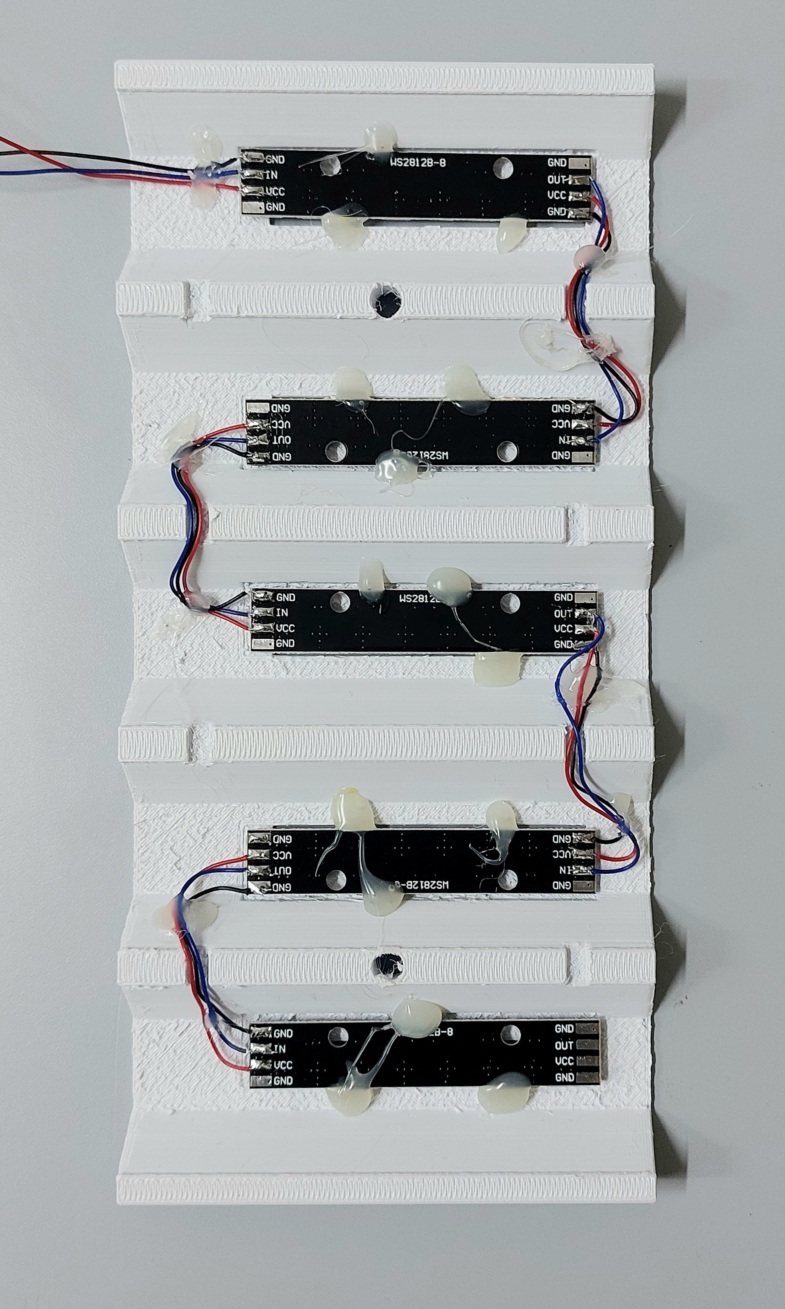
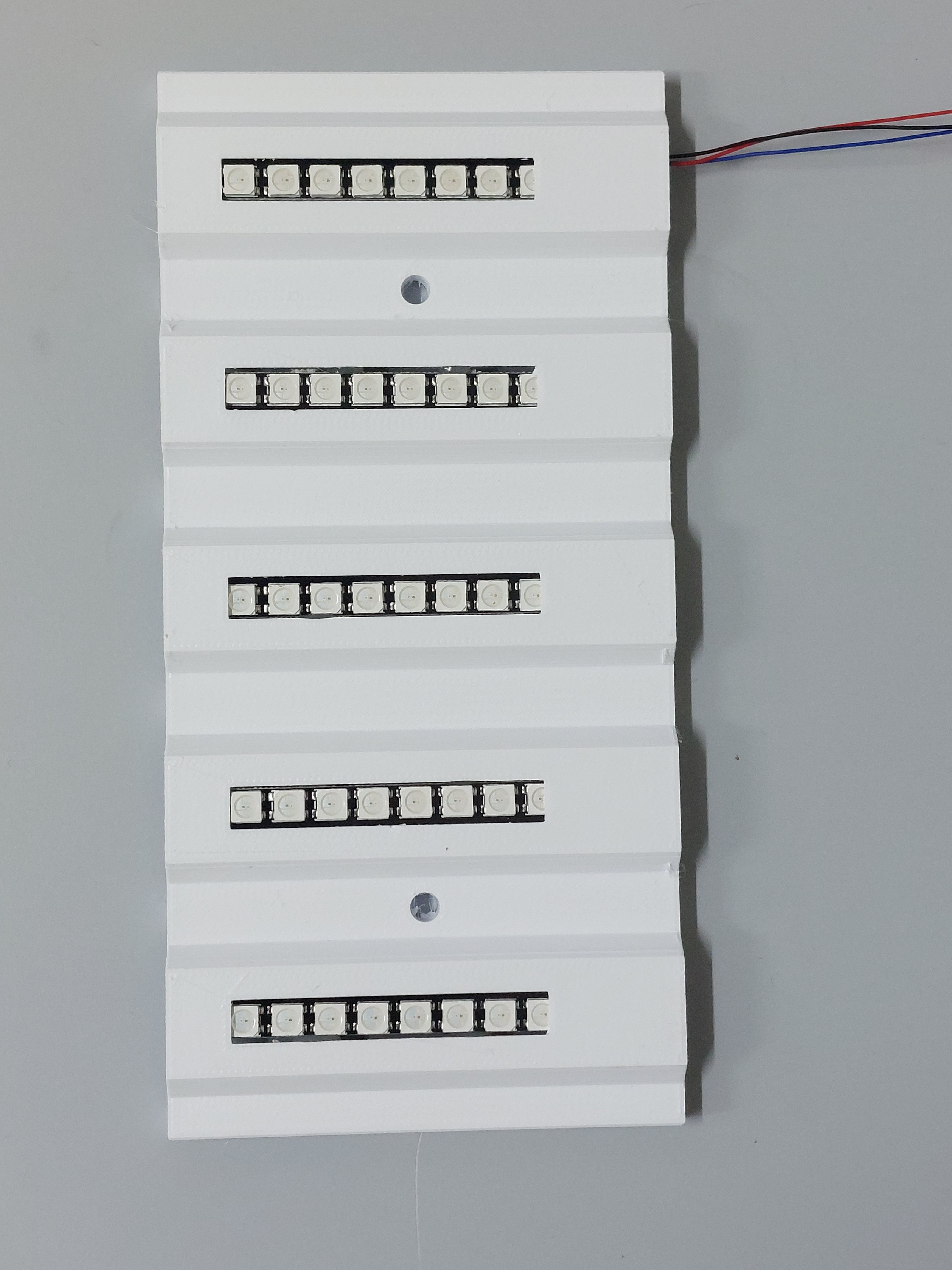
01/05/2025 at 14:13 • 0 commentsThe WS2812B leds are daisy chained in each panel. Since there are four of these panels, they all share the data line. The Arduino "thinks" there are only 40 leds(8x5) but in fact there are 120. The reason for not connecting the panels linearly(thereby daisy chaining all 120 leds) is to reduce communication time. Instead, the connections branch off to the four panels i.e. the wires connect to a screw terminal block on the perfboard.. We do not need the leds to be individually addressable but if all of them are connected linearly then the last (120th) led will take a significant amount of time to respond and this might be an issue when using high stimulation frequencies.
![]()
![]()
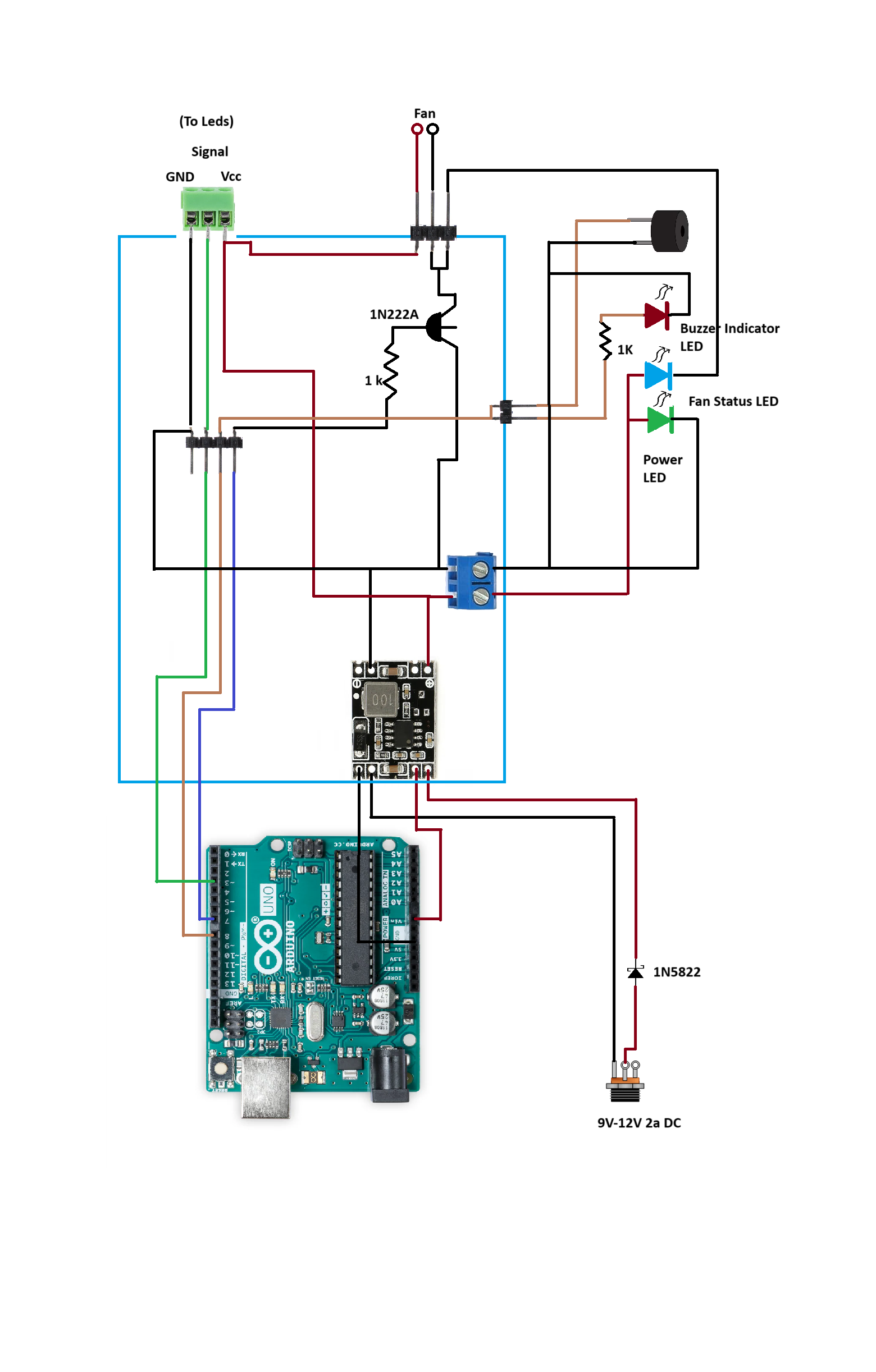
All the peripheral components(indicator leds, buzzer, and cooling fans) are connected to the perfboard. The fans are switched through a transistor since the Arduino itself cannot power two such fans for circulation.
![]()
This is a schematic of the circuit.
![]()
-
3D printed parts
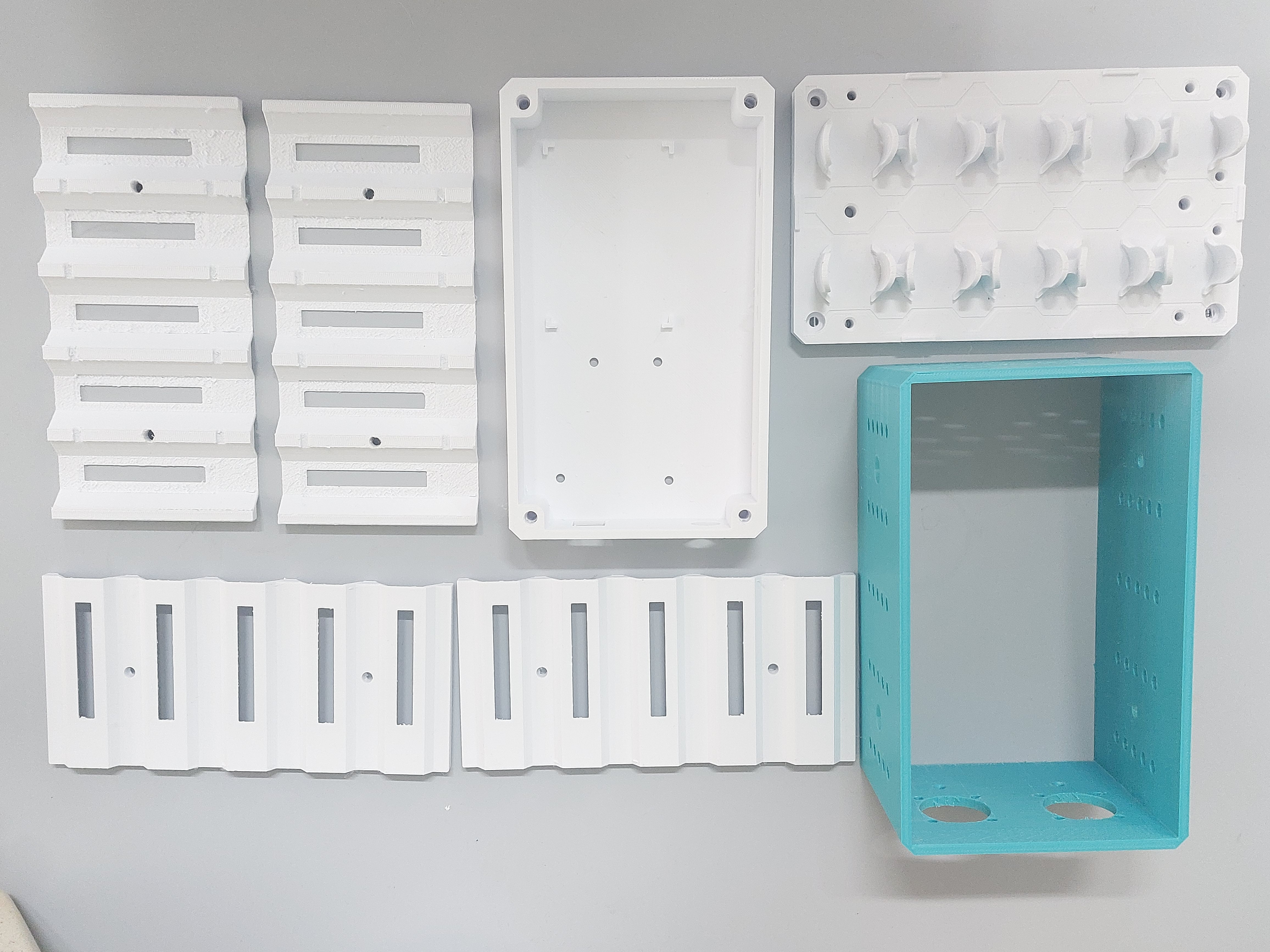
01/05/2025 at 13:54 • 0 commentsThe device is mostly 3D printed. All parts expect the foot pads were printed in PLA+ on a MakerBot MethodX. The foot pads(not shown) were printed in TPU.
![]()
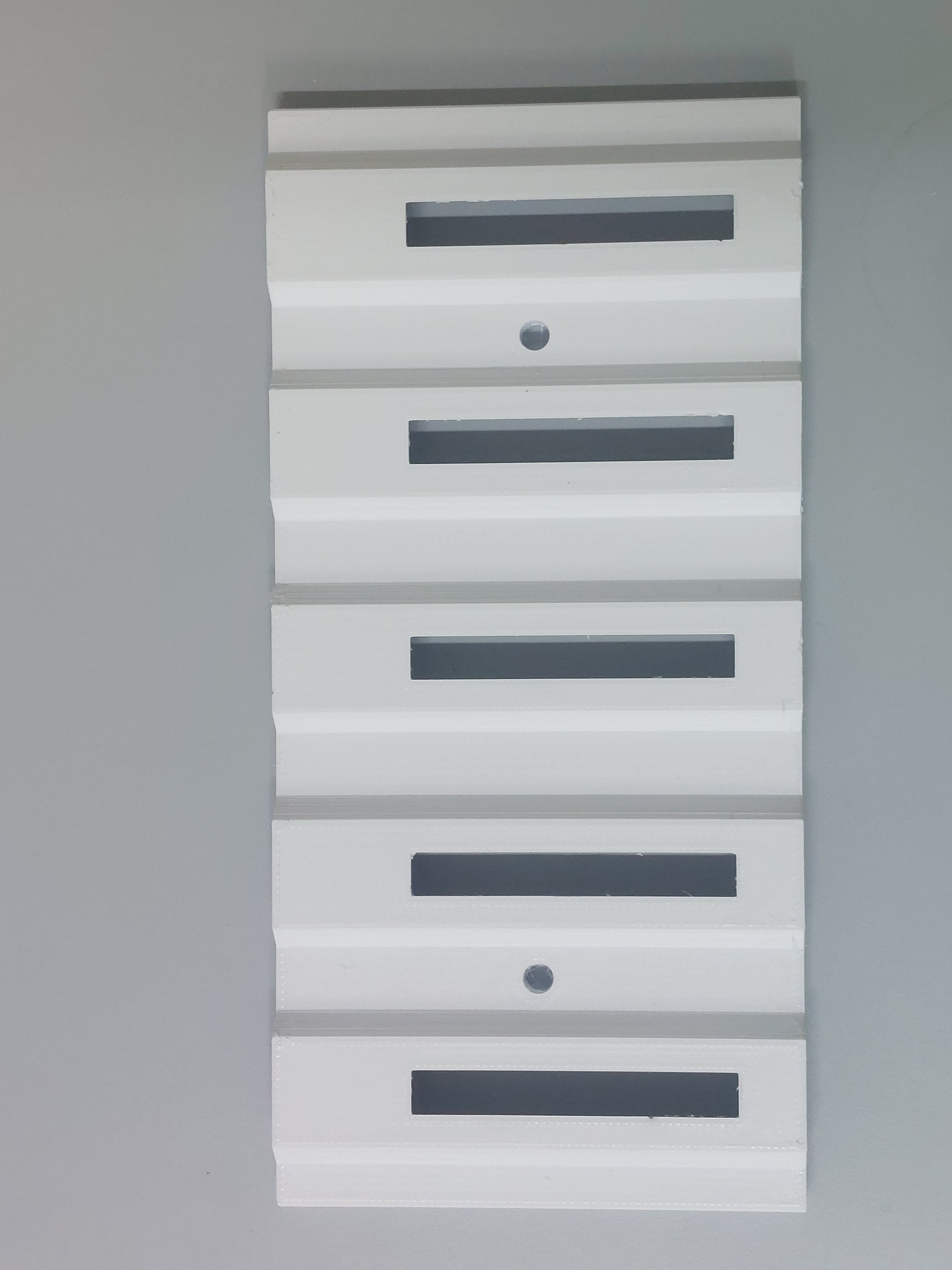
All parts expect the light housing panels are straightforward. The panels (shown below) were printed with the side facing the vials up such that these were smoother and hence more reflective. The breakaway supports are a bit tedious to clean. I would recommend a lower layer height (0.1mm) and a somewhat higher infill (25% or more) to ensure that the part does not snap while removing the supports.
![]()
 Wriju
Wriju