Close
0%
0%

EnviroPi Temp Monitor

Combining a Raspberry Pi Zero 2 WH computer with an Adafruit MCP9808 temperature sensor.

Similar projects worth following
For my first project on Hackaday, I am starting simple by combining a Raspberry Pi Zero 2 WH computer with an Adafruit MCP9808 sensor. The MCP9808 measures ambient air temperature once every second, as orchestrated by the Python programming language. Said data is logged to a CSV file, regularly exported and occasionally visualized using the D3 JavaScript library. The ultimate goal is to discover patterns and trends in how I live daily life within my home.

This project is part of a larger personal interest in DIY self-quantification. And ideally only the beginning of many future endeavors I expect to share on this platform. I am grateful for the ability to express myself through building and cataloging electronics, which is a new passion of mine. Following projects are based on what is learned from documenting this task.

Below are instructions for replicating and running this project. These instructions are gradually being improved. One step at a time.

Instructions

  1. Upload the Python file to a Raspberry Pi Zero 2 WH via SSH and run it using the following command: python3 app.py
  2. Before exiting your terminal session from step one, use Screen to keep the Python file operating.
  3. Allow your Raspberry Pi computer and Adafruit sensor contraption to record data for as long as desired.
  4. Once you have collected enough temperature data, export your temperature_log.csv file from the Raspberry Pi unit, onto your main computer.
  5. Finally, visualize your data using the HTML, CSS and JavaScript files provided on the related GitHub repository.

Please Note

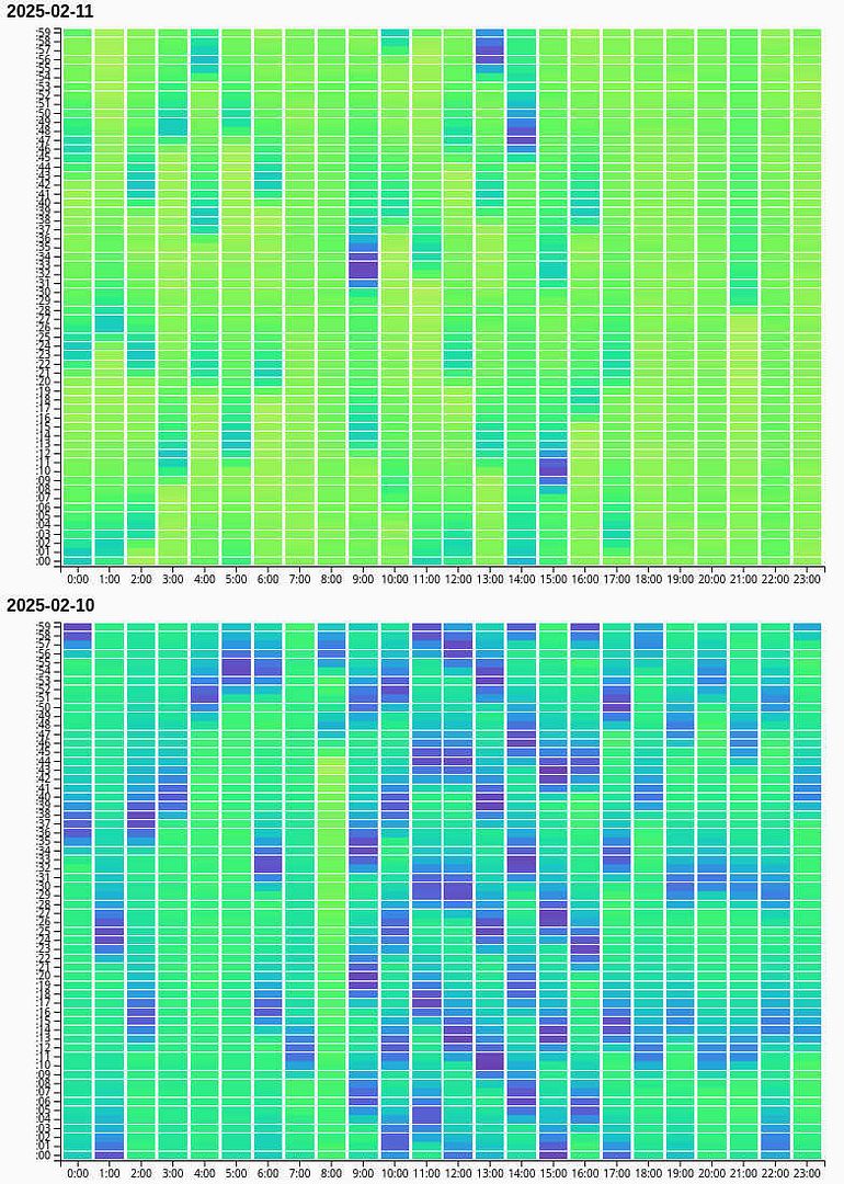
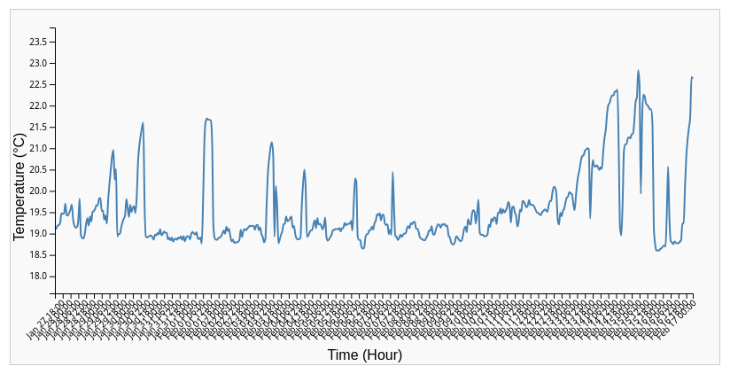
There are three kinds of graphs available for exploring your temperature measurements. The first (type of) chart displays an average twenty four hour period, based on all of your readings. Whereas the second variety of charts displays each day's measurements, from when measurements began until their ending. And the third chart consists of a line graph, which visualizes average hourly temperatures; as seen below.

Also, in my experience, the Python file will generate between three and four megabytes of data every twenty four hours. Although your results may vary.

app.py

The primary Python script for recording temperature readings.

x-python - 1022.00 bytes - 01/28/2025 at 02:38

Download

  • 1 × Raspberry Pi Zero 2 WH
  • 1 × Adafruit MCP9808 Temperature Sensor
  • 4 × Breadboard Jumper Wires

  • Ending Data Collection After Thirty Three Days

    Bret Bernhoft03/01/2025 at 01:47 0 comments

    After thirty three days of collecting temperature readings, I have turned off the Raspberry Pi Zero 2 WH computer. And I will no longer be gathering data for this experiment. As I feel I have enough information to work with towards completion.

    The final CSV file is 78 MB in size, which means the program collected 2.363 MB of data each day. The same CSV file contains 2.75 million measurements, or one for each second between January 27th, 2025 and February 28th, 2025. That is quite a lot from my perspective.

    Looking back on this self-quantification experiment, I am able to see how much I have learned since the beginning. I can also see where overcoming my trepidation about building electronics has now paid off. Documenting the process on Hackaday has been eye opening for me.

    But there are still more details to explore before I walk away from this project. I would like to add a couple more steps to the EnviroPi Temp Monitor page. As well as expand on the details section for other newcomers who may be interested in building this project for themselves.

  • Results From Sixteen Days Of Temperature Readings

    Bret Bernhoft02/13/2025 at 02:44 0 comments

    After running this project for roughly sixteen days, the CSV file containing all of the temperature measurements (from the MCP9808 sensor) is roughly thirty nine megabytes in size. Which is almost two and a half megabytes of data gathered every day; a little less than originally estimated.

    What I have also noticed is every twenty four hour period has a distinct fingerprint or pattern, in terms of the temperature readings collected. This is validated with the visualizations provided for each calendar day using the HTML and JavaScript files available on GitHub. Further still, by referencing the same graphs, I am able to determine the exact minute when environmental services in my home are automatically turned on. All being rather interesting and revealing to me. 

    Please see the screenshot below for an example of what is stated in the above paragraph:

    This self-quantification project has been a lot of fun to build, document and maintain. I expect to be actively gathering temperature readings for a little less than two more weeks. Resulting in a total of four weeks worth of entries. When completed, I will be moving on to another similar project, to be documented via a Hackaday project page.

  • Temperature Measurements Actively Being Recorded

    Bret Bernhoft01/28/2025 at 02:33 0 comments

    After a couple hours of work, to my great delight and relative astonishment, the Adafruit MCP9808 sensor has been successfully connected to the Raspberry Pi Zero 2 WH computer. The contraption is actively measuring ambient temperatures once per second, and storing said data in a common, local CSV file.

    I will run this experiment for roughly two or three weeks. Afterwards, I will export and visualize the information using D3; my favorite data graphing JavaScript library. In the meantime this "EnviroPi Temp Monitor" project needs to be clearly organized, including the addition of Python scripts and instructions on how to replicate.

    To keep things interesting, I am dreaming up my next Hackaday.io project. But that is fun for another time. Let's stay (mostly) focused on what is already in front of us. There is still a bit more to do here.

  • My First Attempt At Soldering Was A Success

    Bret Bernhoft01/16/2025 at 02:44 0 comments

    Tonight I soldered header pins to the Adafruit sensor I am using for this project. I noticed the temperature on my Weller soldering iron varied quite a bit during the soldering process. But after cleaning the iron's tip, everything stabilized as expected.

    What makes this soldering especially interesting and notable to me, is the fact tonight is my first time ever trying. And it was a success. The joints are solid, there are no solder bridges and I didn't use excessive material.

    The next step is to test the sensor component's connectivity with my Raspberry Pi computer. If I am able to verify the two are communicating, I can write the software for collecting temperature readings. And get this project on its way in earnest.

  • Purchased Soldering Equipment Today

    Bret Bernhoft01/11/2025 at 03:00 0 comments

    As this is my first Hackaday.io project, it is also my first attempt at soldering. While I have already been using Raspberry Pi computers and the Python programming language for self-quantification, my experience with assembling electronics is relatively limited. I have built numerous desktop PCs, but only a few devices weighing less than a pound or two.

    Today I purchased the equipment needed to solder. Once the hardware arrives, I will begin this journey by connecting header pins to the Adafruit MCP9808 temperature sensor. From there, I will be using jumper cables to connect said sensor to a Raspberry Pi Zero 2 WH. At which point I will write a program to have this apparatus collect temperature data every few seconds, adding those measurements to a growing CSV file. Which will later be visualized using the D3 JavaScript library.

    I will update this project again in the near future when there is more to share.

View all 5 project logs

  • 1
    Solder Header Pins Onto The Adafruit MCP9808 Temperature Sensor

    After acquiring the necessary components, the first step is to solder header pins onto the Adafruit MCP9808 temperature sensor, in order to secure a firm connection for data transfer. To accomplish this I used a Weller Soldering Kit, helping hands platform and protective eye goggles.

    The soldering process, from start to finish, took me roughly thirty minutes. Although said session was my first ever attempt at soldering. So, depending on your experience level, this step may take less time for you.

    After completing this step, to ensure the header pins were properly connected, I removed the newly assembled sensor from the helping hands platform and gently attempted to "wiggle" the header pins loose. To my great delight, my soldering firmly embedded the header pins into the sensor board.

  • 2
    Connect The Adafruit MCP9808 Sensor To The Raspberry Pi Zero 2 WH GPIO Pins

    Assuming your soldering of the MCP9808 header pins was successful, the next step is to connect the sensor to your Raspberry Pi Zero 2 WH using four jumper wires. To accomplish this, I used four female-to-female jumper wires purchased online.

    Before connecting the jumper wires to either the sensor or the RPi, please make sure your Raspberry Pi computer is powered off. This is to avoid short circuits or accidental damage. As well, your jumper cables should ideally be twelve inches or less in length, to avoid picking up unwanted environmental noise.

    Once your preparations for this step are complete, the specific connections you will need to make are as follows:

    1. VIN (MCP9808) to 3.3V (Pin 1 on the Pi)
    2. GND (MCP9808) to GND (Pin 6 on the Pi)
    3. SCL (MCP9808) to GPIO3 (SCL) (Pin 5 on the Pi)
    4. SDA (MCP9808) to GPIO2 (SDA) (Pin 3 on the Pi)

    Make sure the jumper wires you are connecting the temperature sensor to the Raspberry Pi with are snug and well-fit.

  • 3
    Power On The Raspberry Pi Zero 2 WH And Verify The Temperature Sensor Is Detected

    With your Adafruit MCP9808 temperature sensor connected to your Raspberry Pi via jumper cables, it is time to power on the RPi computer. Which is accomplished by plugging the correct power cable into the Raspberry Pi 2 WH and letting the unit boot. Once the Raspberry Pi OS has loaded, open a terminal on the Pi, either through direct access with a monitor, keyboard and mouse. Or through a SSH connection from another machine.

    The I2C interface needs to be enabled for the Raspberry Pi to communicate with the MCP9808 sensor. Accomplished by running the following command in your open terminal: sudo raspi-config. Then navigate through the menu using your keyboard's arrow keys by first selecting Interfacing Options. Next, select I2C and choose Enable. Press Enter to confirm and exit the configuration tool. Now reboot the Raspberry Pi to apply the changes by running the following command in your terminal: sudo reboot.

    To check if the Adafruit MCP9808 sensor is connected, install the i2c-tools package by running the following commands in a new terminal window: sudo apt update and then sudo apt install -y i2c-tools. This package provides tools to scan and communicate with I2C devices. Finally, run the following command in an open terminal window on your Raspberry Pi Zero 2 WH computer to scan I2C devices on bus one: i2cdetect -y 1.

    You should see a grid output with 0x18 as the address for the MCP9808 sensor.

View all 4 instructions

Enjoy this project?

Share

Discussions

Similar Projects

Does this project spark your interest?

Become a member to follow this project and never miss any updates