The PCB Assembly Process for this project begins with applying solder paste to each component pad with a solder paste dispensing needle. We're using 63/37 Sn-Pb solder paste.
Next, we select all of the SMD components and place them in the correct spot.
We next place the board on our Reflow Hotplate, which heats the PCB from below up to the solder paste melting temperature of roughly 200 °C. Solder paste melts permanently and connects all SMD components to their pads.
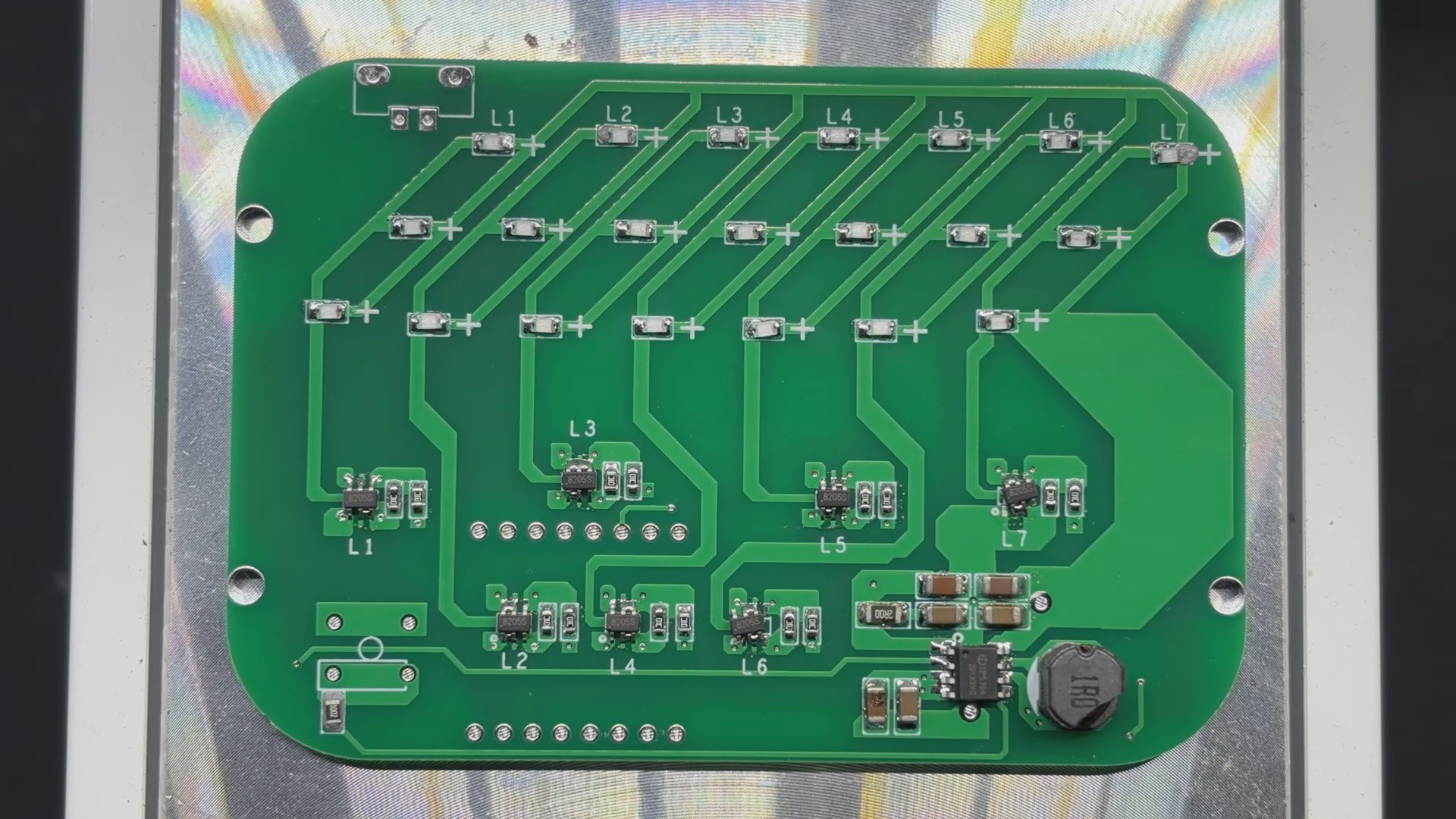
This concludes the SMT Process.
2
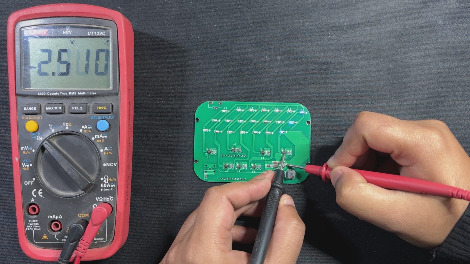
Testing the LEDs
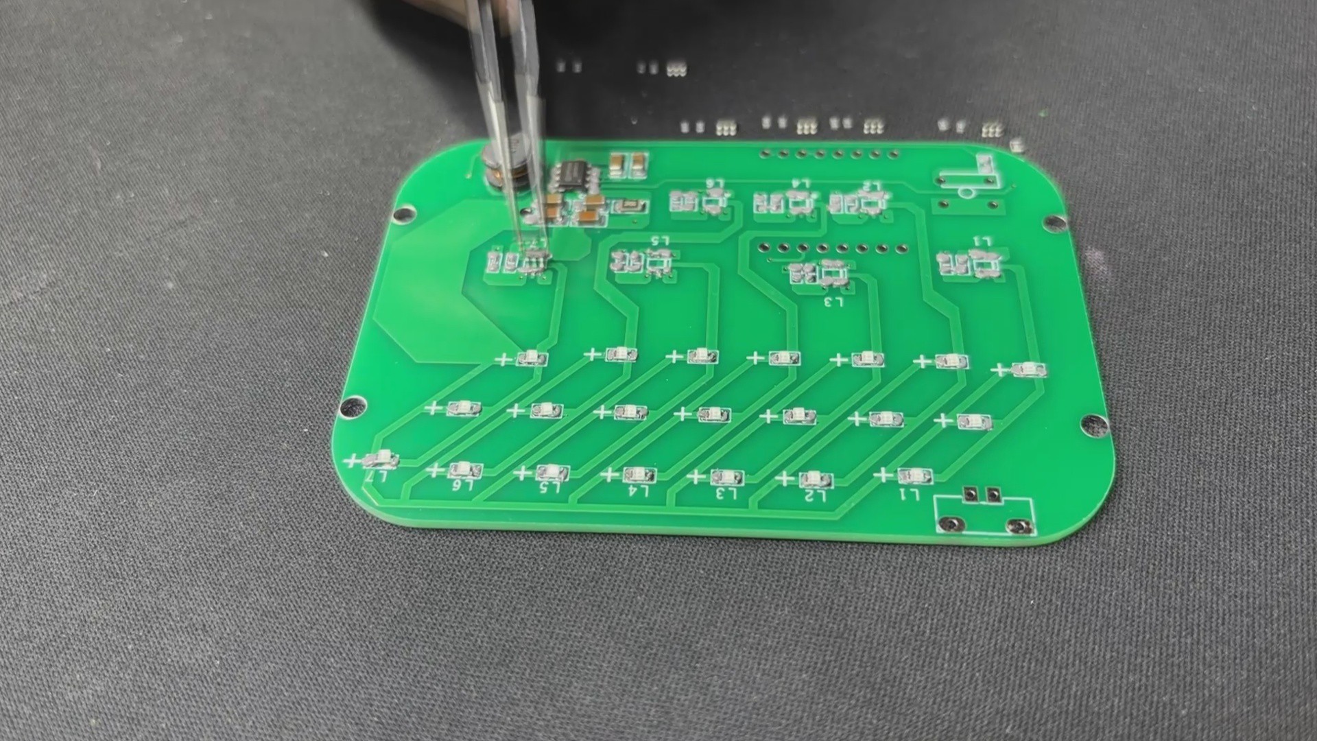
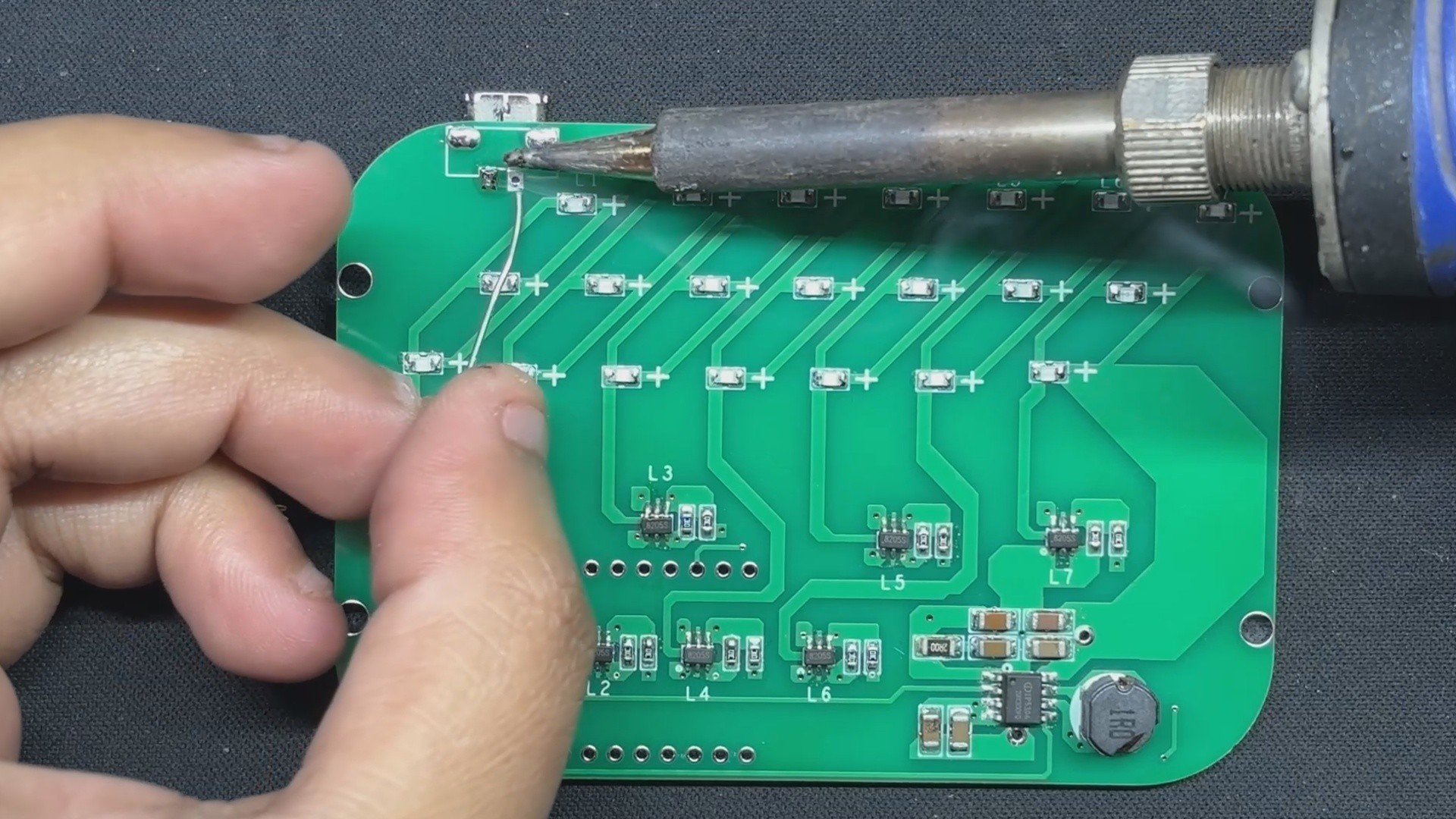
Before proceeding with the rest of the build, we must ensure that all LEDs are properly installed on their pads. To do so, we utilize our multimeter and set it to diode checking mode.
The positive probe of the multimeter is then connected to the 5V terminal on the board, and the negative probe of the multimeter is set to the drain of each mosfet one at a time. Each LED section lights up, indicating that they are soldered properly.
3
Rest of PCB Assembly Process
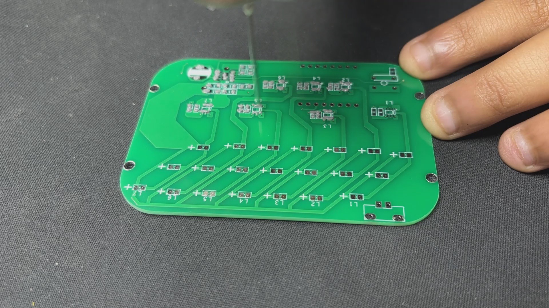
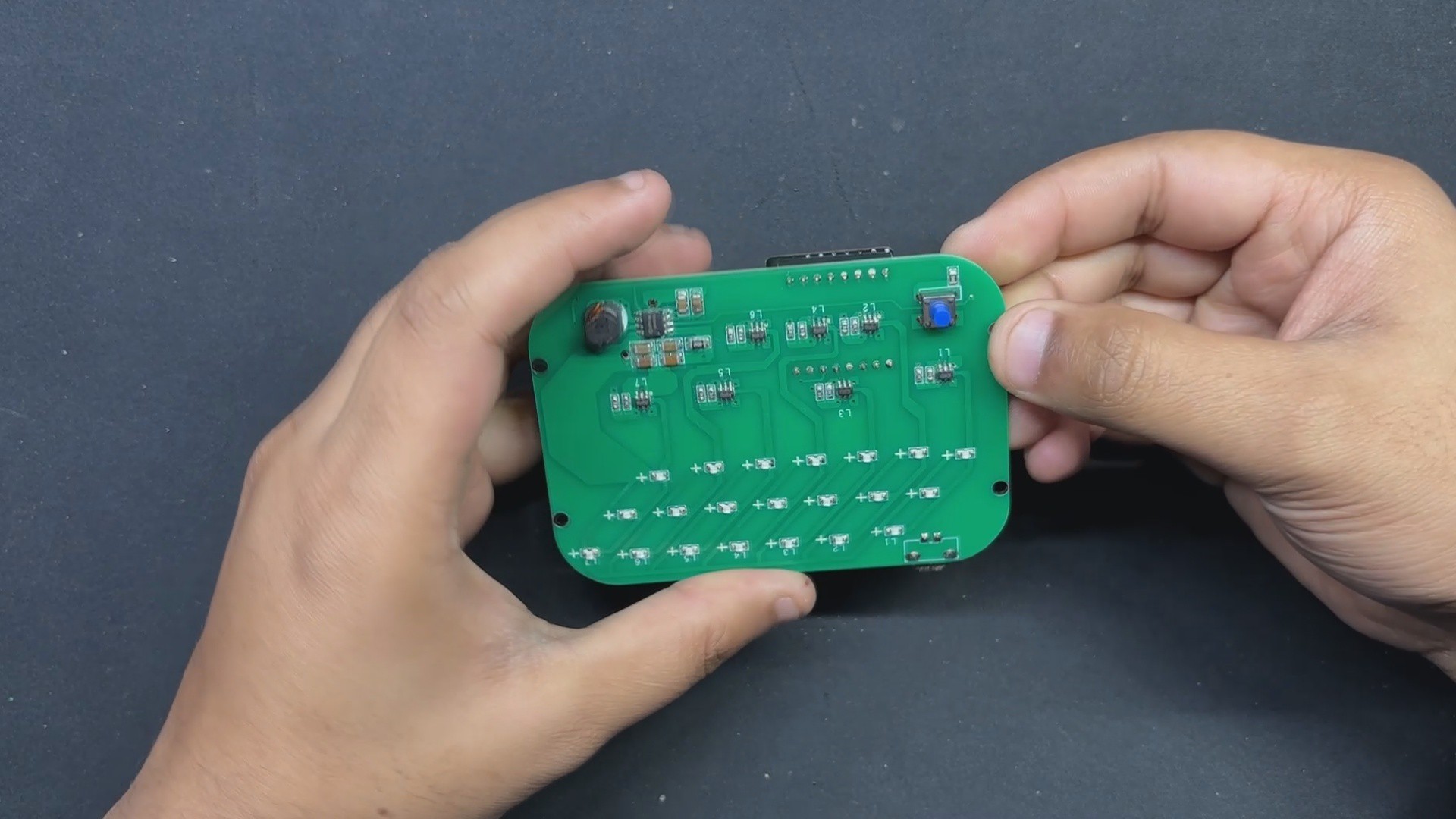
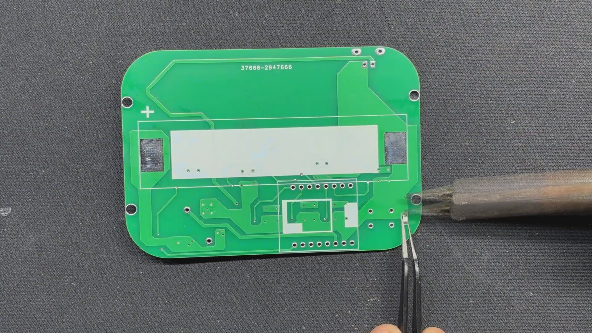
We will now resume the board assembly procedure by turning the board over to add an indication LED. We begin by applying solder to one of the pads on the PCB, then heating the solder and sliding the LED into position, which will join the LED terminal to one side of the pad. We then apply solder to the other side of the LED and melt it with the soldering iron, locking it in place.
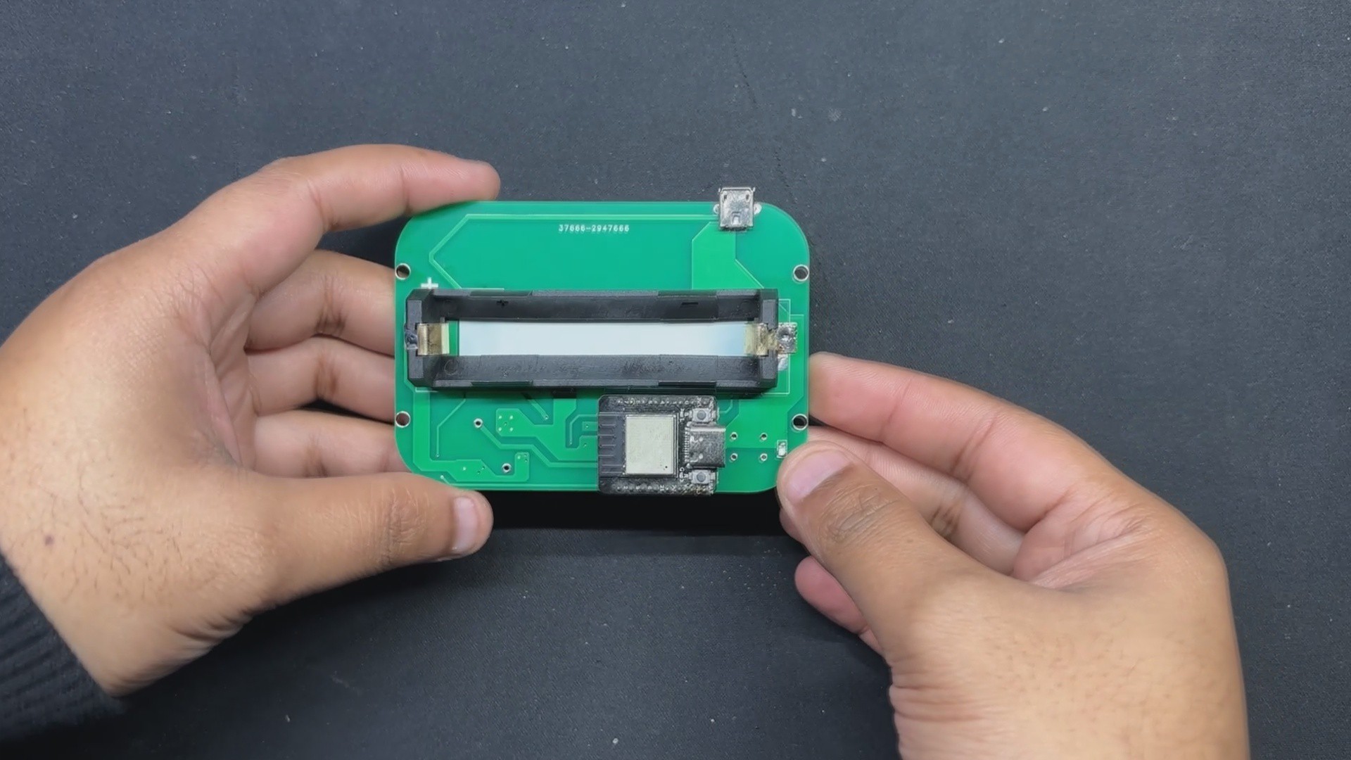
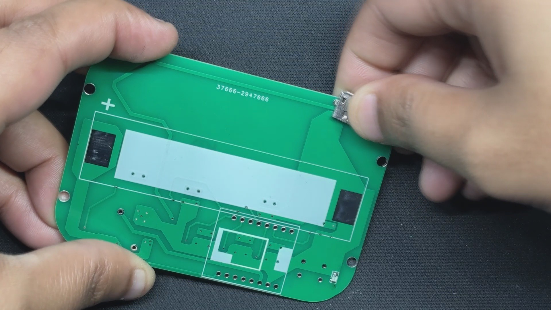
The Micro Type B USB Port is then installed from the bottom side of the board, and its pads are soldered from the top side.
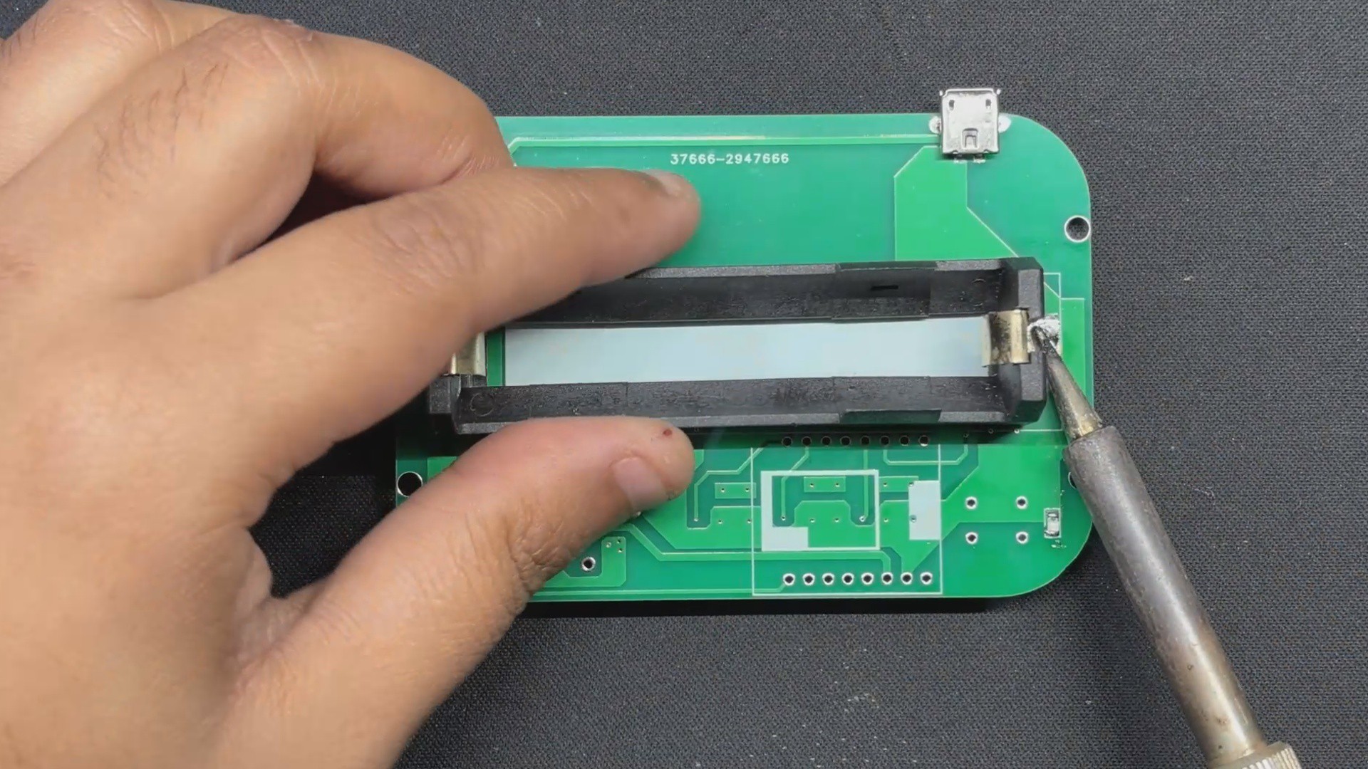
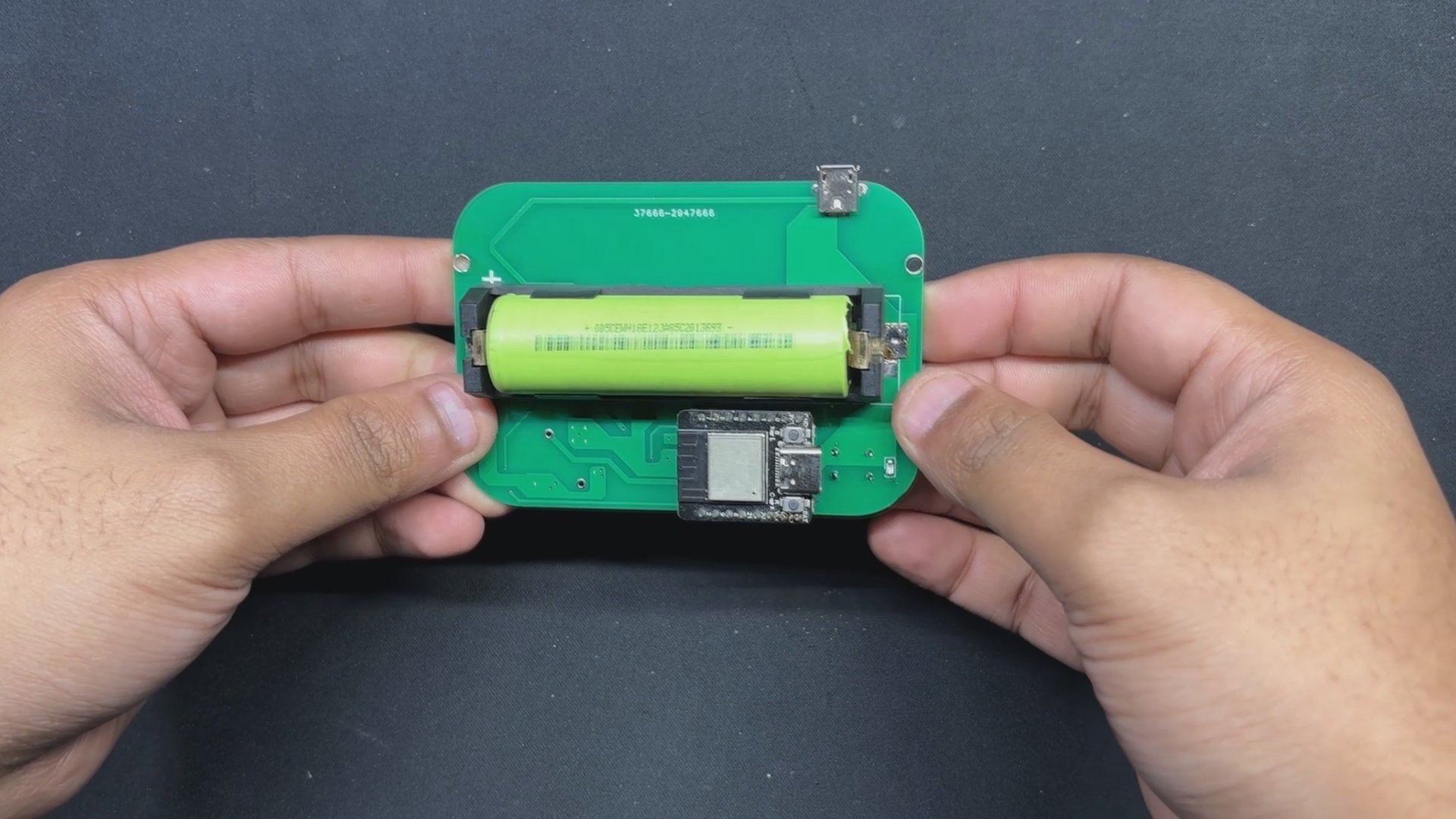
Next, sat the Lithum cell holder over the pads and secured it with a soldering iron.
Following that, we install the DF Mini Beetle in its proper location and solder its pads to the board.
We attached a push button to the top side of the board and soldered it in place with a soldering iron.
The Board Assembly process has now been completed.
4
Power Source
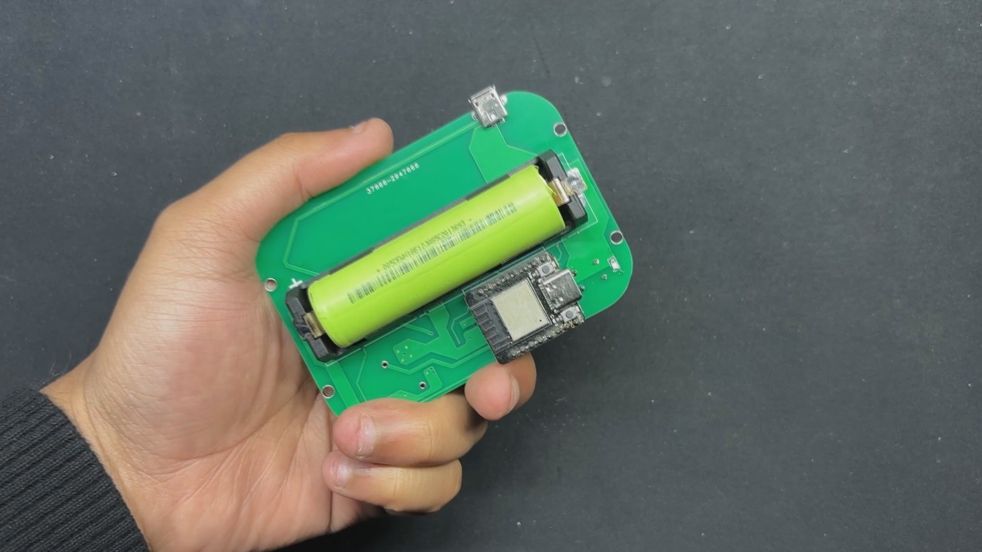
This project's power supply is a 3.7V 2200mAh Li-ion cell, which is placed into the lithium cell holder and positioned correctly.
By pressing the switch once, the device turns on, indicating that the setup is working.
5
Final Assembly
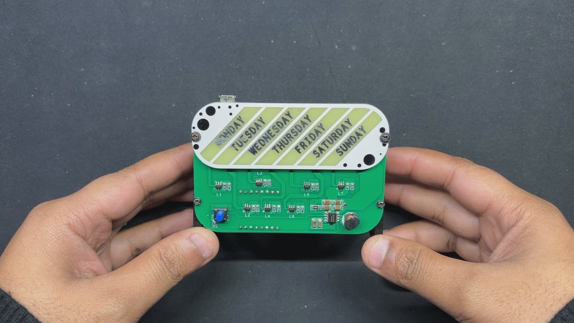
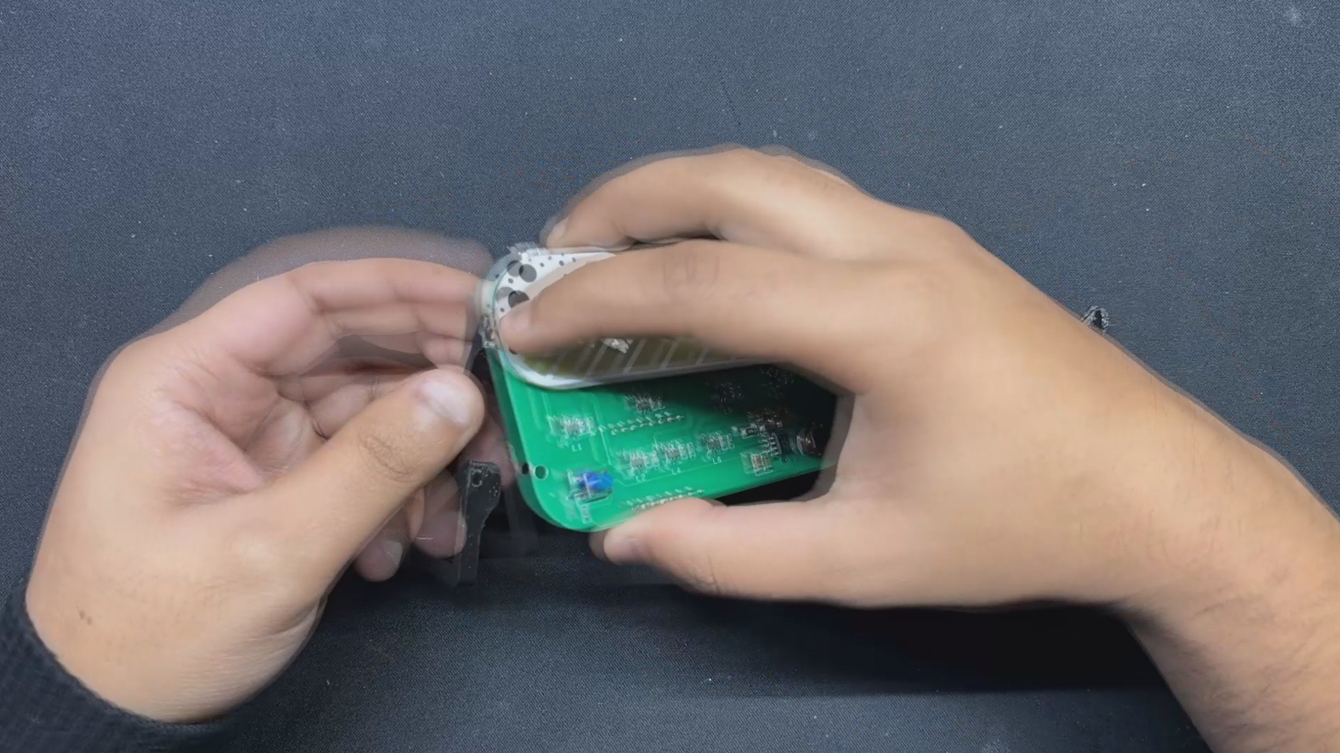
The final assembly process begins with the placement of the Sepearator layer on the driver board, followed by the placement of the ART PCB over it. We then put the left and right stands in their respective positions and attached them together with four M2 screws.
The week clock assembly has now been completed.
6
Main Code
We uploaded the following code to our Mini Beetle board after completing the assembling process. The main sketch connects the ESP32 to a router, allowing the device to receive NTC values from the internet. Before you use the sketch, make sure you enter your own SSID and password.
#include<WiFi.h>#include<NTPClient.h>#include<WiFiUdp.h>// Define LED pins#define LED_PIN_1 0#define LED_PIN_2 1#define LED_PIN_3 4#define LED_PIN_4 5#define LED_PIN_5 6#define LED_PIN_6 7#define LED_PIN_7 2constint ledPins[] = {LED_PIN_1, LED_PIN_2, LED_PIN_3, LED_PIN_4, LED_PIN_5, LED_PIN_6, LED_PIN_7};
// Number of LEDsconstint numLEDs = 7;
constint ledBrightness = 128; // 50% brightness (128 out of 255)// WiFi credentialsconstchar* ssid = "UR SSID";
constchar* password = "UR PASS";
// Define NTP Client to get time
WiFiUDP ntpUDP;
NTPClient timeClient(ntpUDP, "pool.ntp.org", 19800, 60000); // IST timezone offset (19800 seconds)unsignedlong lastChange = 0;
// Function to connect to Wi-FivoidconnectToWiFi(){
Serial.print("Connecting to WiFi...");
WiFi.begin(ssid, password);
while (WiFi.status() != WL_CONNECTED && millis() < 20000) { // Limit connection attempt to 20 seconds
delay(500);
Serial.print(".");
}
if (WiFi.status() == WL_CONNECTED) {
Serial.println("Connected to WiFi");
} else {
Serial.println("Failed to connect to WiFi");
}
}
voidsetup(){
Serial.begin(9600); // Changed baud rate to 9600for (int i = 0; i < numLEDs; i++) {
pinMode(ledPins[i], OUTPUT);
Serial.print("Setting up LED "); // Adding more debug info
Serial.println(ledPins[i]);
digitalWrite(ledPins[i], LOW); // Initialize all LEDs to 'off'
}
connectToWiFi();
timeClient.begin();
}
voidloop(){
Serial.println("Loop started"); // Debugging lineif (WiFi.status() == WL_CONNECTED) {
timeClient.update();
int dayOfWeek = timeClient.getDay();
Serial.print("Day of Week: "); // Debugging line
Serial.println(dayOfWeek); // Debugging line// Mapping dayOfWeek to correct LED (0 = Sunday, 1 = Monday, ..., 6 = Saturday)int ledIndex = (dayOfWeek + 6) % 7;
Serial.print("LED Index: "); // Debugging line
Serial.println(ledIndex); // Debugging linefor (int i = 0; i < numLEDs; i++) {
digitalWrite(ledPins[i], LOW); // Turn off all LEDs
Serial.print("Turning off LED "); // Debugging line
Serial.println(ledPins[i]); // Debugging line
}
digitalWrite(ledPins[ledIndex], HIGH); // Turn on the correct LED for the day at 50% brightness
Serial.print("Turning on LED "); // Debugging line
Serial.println(ledPins[ledIndex]); // Debugging line
} else {
// Default behavior to turn all LEDs off if not connected to Wi-Fi
Serial.println("Wi-Fi not connected, turning off all LEDs"); // Debugging linefor (int i = 0; i < numLEDs; i++) {
digitalWrite(ledPins[i], LOW); // Turn off all LEDs
}
}
delay(1000); // Update every second
Serial.println("Loop ended"); // Debugging line
}
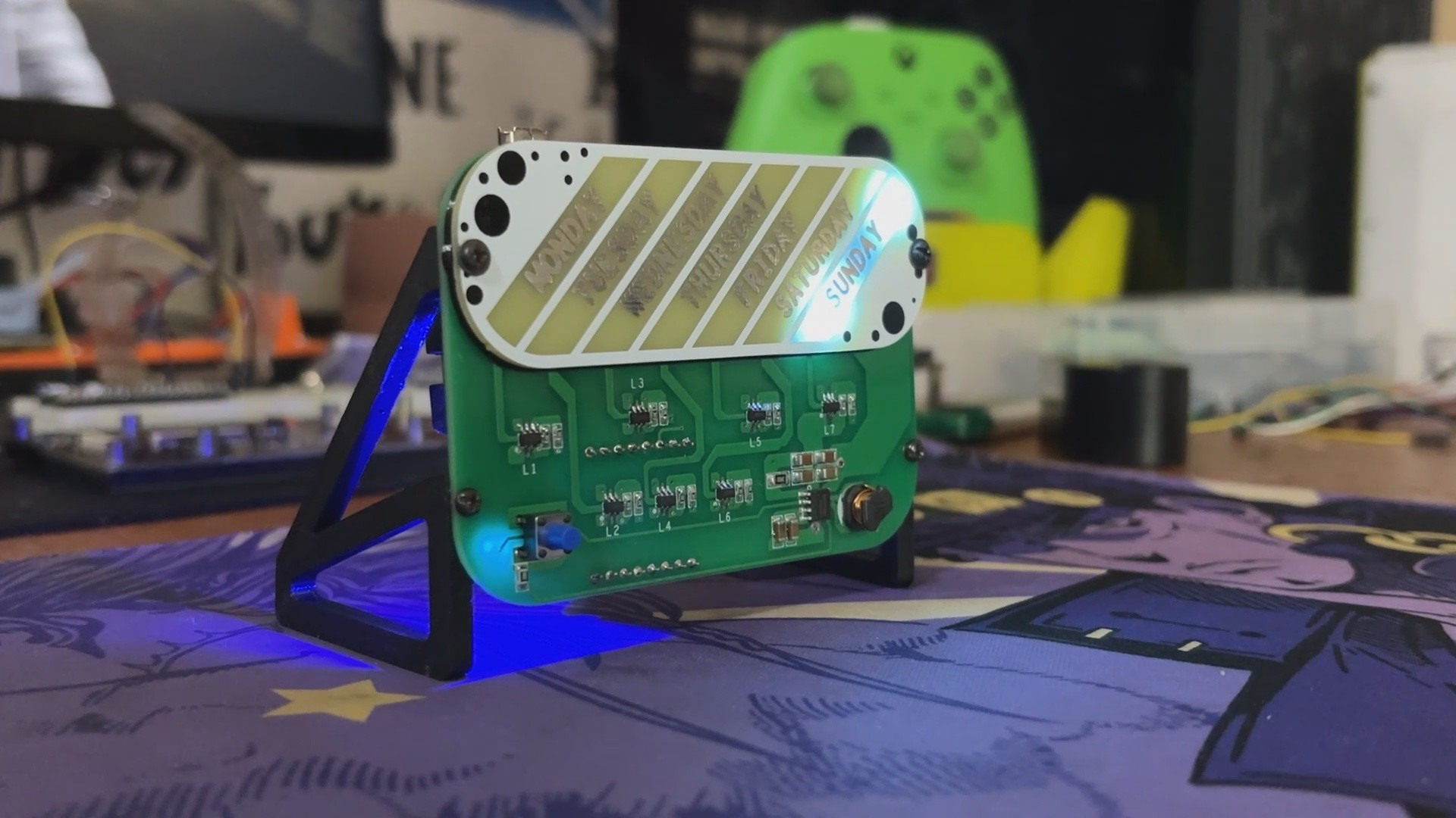
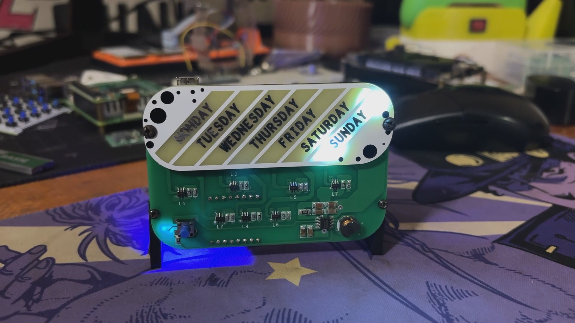
This project resulted in the Week Clock, which illuminates a segment of the Art PCB to signify the current day. We finished this project on Sunday; therefore, the Sunday part is currently illuminated. As the days pass, the matching segment will light up in a continuous cycle.
Overall, this project is performing fine, but one thing we would like to change is the lower visible section. In the next iteration, we will completely remodel this clock, giving it a new clock-like design.
Special thanks to HQ NextPCB for providing components that I've used in this project; check them out for getting all sorts of PCB or PCBA-related services for less cost.
Thanks for reaching this far, and I will be back with a new project soon.
 Arnov Sharma
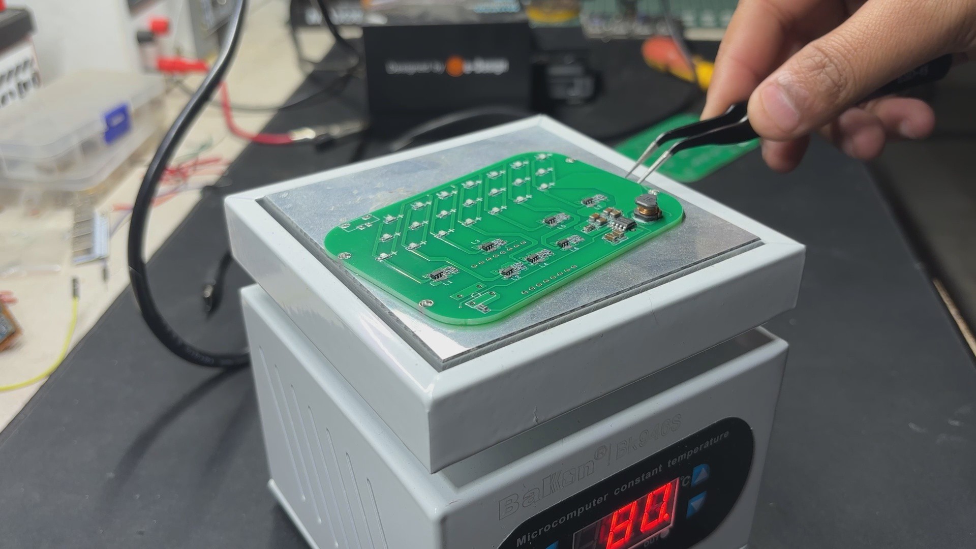
Discussions
Become a Hackaday.io Member
Create an account to leave a comment. Already have an account? Log In.