Li Wei
-
I Tested My Carrier / LED Driver Board.
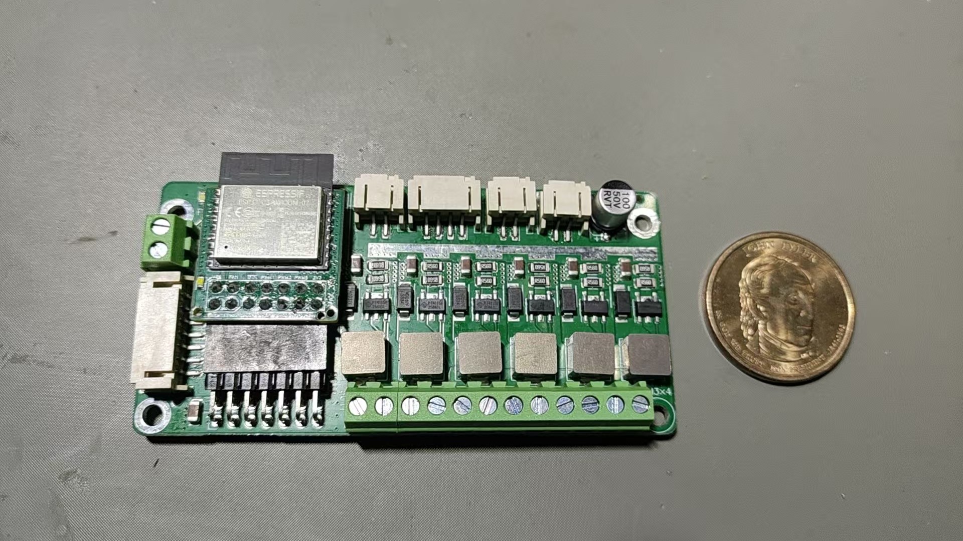
05/13/2026 at 14:45 • 0 commentsI tested my carrier/driver board.
![]()
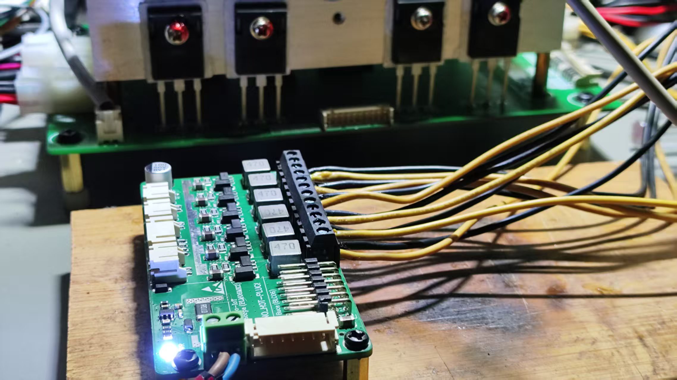
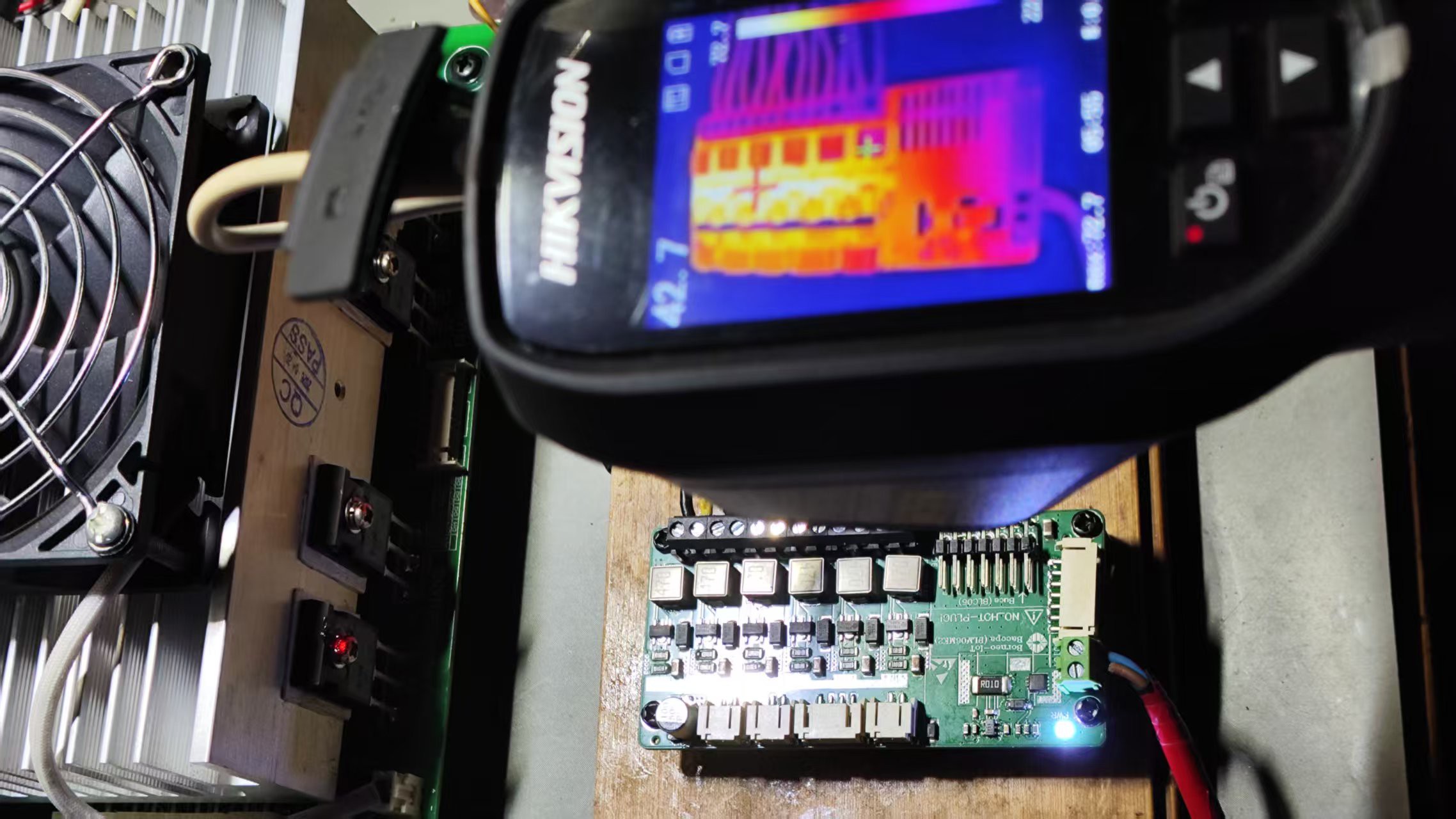
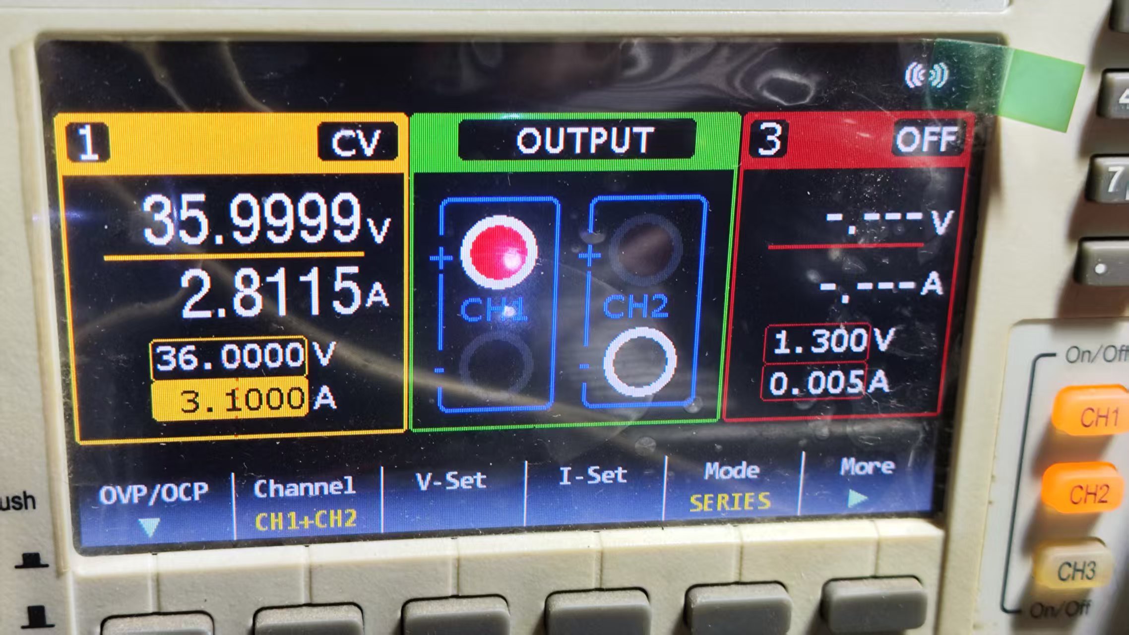
Here is the data at 100W, under passive cooling (fanless), with an ambient temperature of 24°C, six channels each at 23.5V and 0.7A. The maximum surface temperature of the PCB stabilizes at around 80°C. With slight forced air cooling, it can be reduced to 54°C.
![]()
![]()
![]()
The thermal design and power density look good to me.
-
My ESP32-C3 Based Open Source Aquarium LED Controller Hits Crowdfunding
09/20/2025 at 07:06 • 0 commentsHi Hackaday readers,
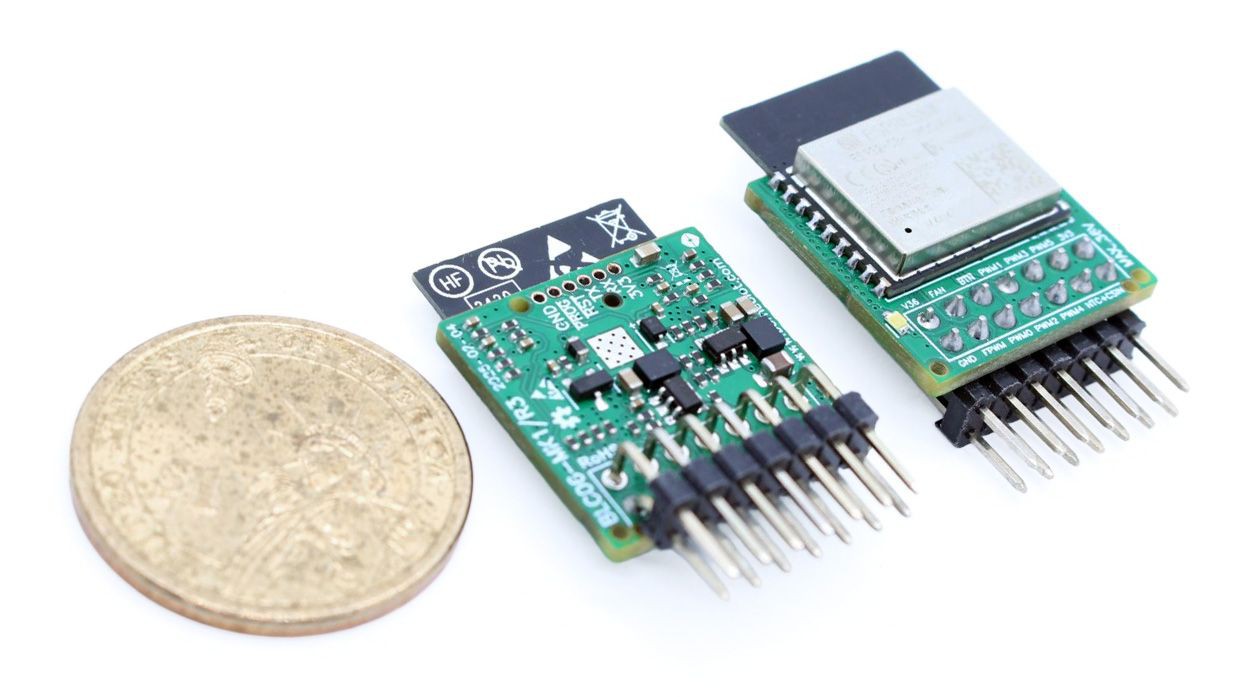
Over the past year I’ve been developing Buce, a compact open-source LED controller for aquariums. Built around the ESP32-C3, it was inspired by my own DIY reef light projects, and I finally decided to launch a crowdfunding campaign to make it available to others.
![]()
What Buce does
Buce can drive 6 independent PWM channels with high-resolution dimming and supports multiple dimming curves for realistic lighting. It connects via Wi-Fi and can be controlled through the Android app I developed (iOS version in progress).Open Source
All hardware design files and firmware are fully open-source and OSHWA certified. If you prefer, you can skip the crowdfunding and manufacture the PCB yourself. The firmware supports OTA updates, over-temperature protection, and over-voltage protection.Why crowdfunding
Launching Buce via Crowd Supply allows me to gauge interest, fund the first production run, and make it easier for others to get started without having to build everything from scratch.If you want to try your hand at a DIY aquarium lighting controller, or simply want to support open-source ESP32 hardware, you can check out the project here:
https://www.crowdsupply.com/borneo-iot/buce-aquarium-led-controllerCheers!
-
App Upate
08/03/2025 at 08:14 • 0 commentsI've recently spent some time polishing this app.
If you’re interested, you can download the pre-compiled Windows and Android versions from GitHub:
https://github.com/borneo-iot/borneo/releases -
6-Channel Reef LED Working-in-Progress
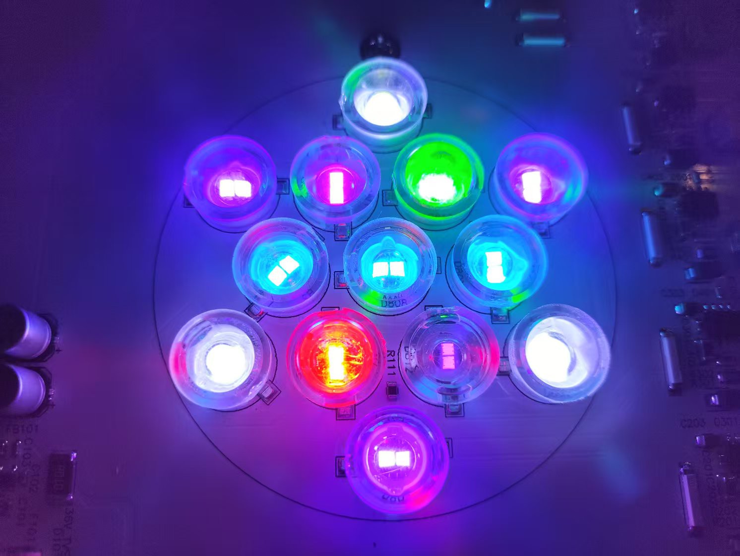
04/17/2025 at 15:39 • 0 commentsI'm so excited to share my latest work: a 65W open-source WiFi-controlled LED aquarium light prototype for reef tanks, powered by my ESP32-C3 based LED controller.
Beautiful, isn't it?
![]()
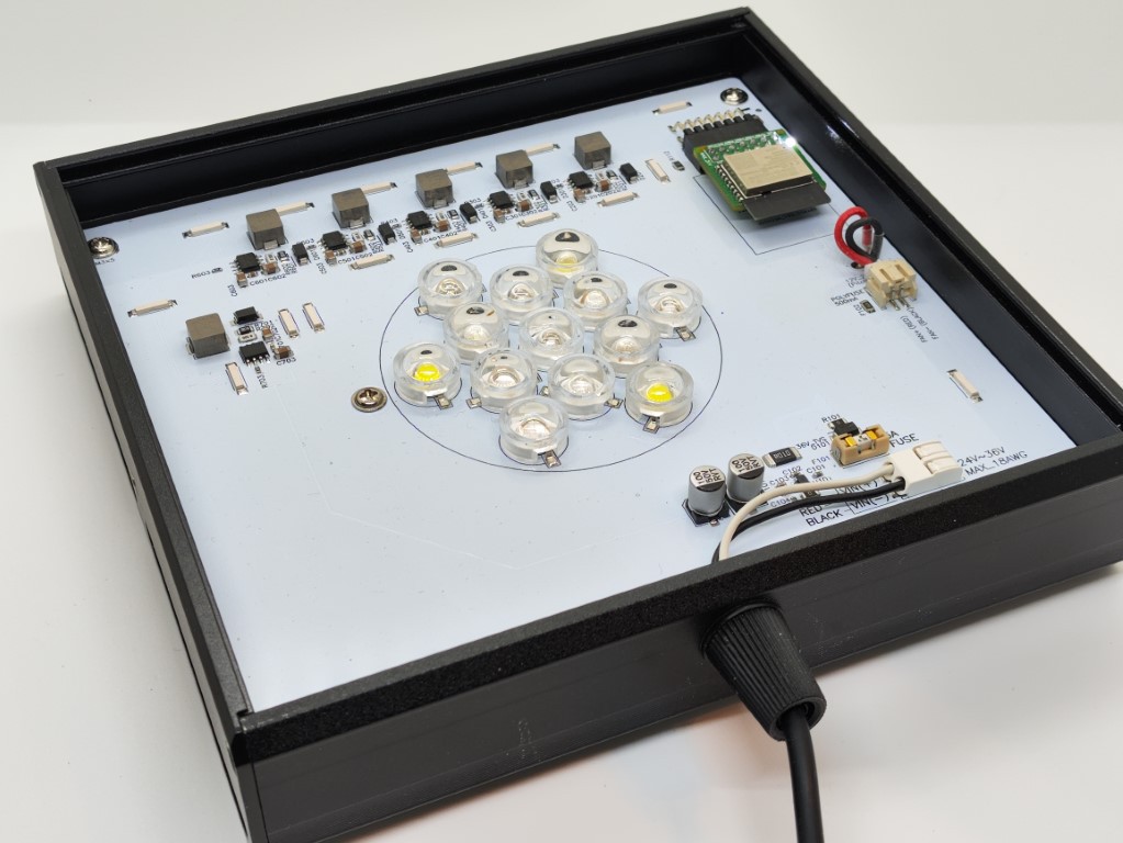
Here is the enclosure:
![]()
![]()
![]()
The white aluminum PCB is the main power board, which includes six sets of LED constant-current driver circuits, a simple current detection circuit, and the LED chips themselves. This part is flexible and can be arranged in any layout. The aluminum PCB design shown in the sample picture hasn’t been open-sourced yet. I’ll open-source it once testing and fixes are complete, I don’t want anyone making the world better before I do :)
I chose a dual-chip packaged 5W model. The current prototype has a constant-current drive set to 1.2A per channel, with an actual power output of up to 64W. For the next iteration, I plan to reduce the current a bit to better extend the LED lifespan.
![]()
![]()
The number and wavelengths of the LEDs are as follows:
- 1 x red, 620-630nm
- 1 x green, 520~530nm
- 1 x purple, 410~420nm
- 3 x cold white 10000k
- 3 x royal blue 440nm~450nm
- 1 x UV 390nm
- 3 × blue, 465nm~475nm
I use LED chips from a Chinese manufacturer, which I’ve been buying from for years for DIY projects. I have DIY creations that have been running stably for over 5 years.
I use the most advanced common-anode constant-current driver to avoid the thermal runaway and burnout issues that most hobbyists face with constant-voltage drivers. Combined with a fuse, software-controlled temperature fan, and real-time current detection, I can confidently say this is one of the most advanced and safest in the world.
The acrylic panel for this light hasn’t arrived yet. Once it does, I’ll upload more pictures of the product’s appearance.
TO BE CONTINUED...
-
Buce LED PWM controller fan driver load test
03/13/2025 at 07:39 • 0 commentsSo today, I conducted a long-duration (over two hours) fan driver circuit load test for my Buce module.
![]()
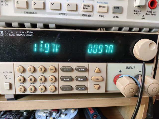
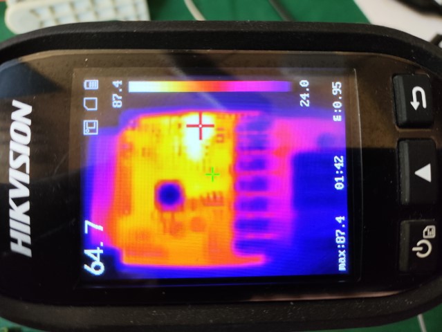
This is a load test of the fan driver circuit continuously outputting 100mA of current. As seen, the inductor heated up to 59.1°C (with an ambient temperature of 21°C and a supply voltage of 30V).
![]()
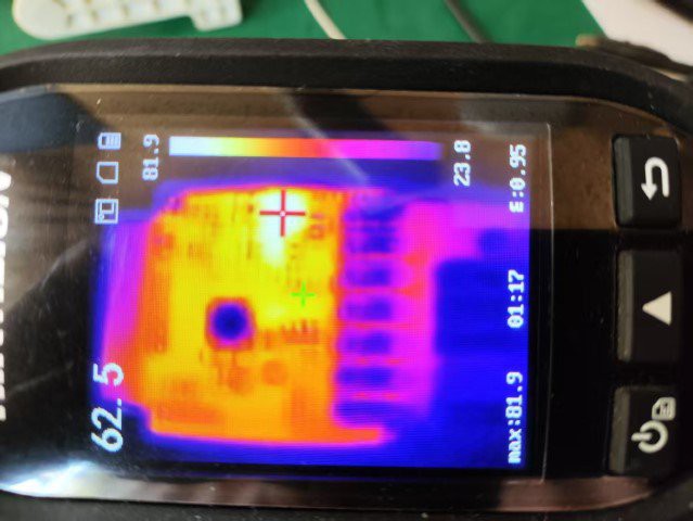
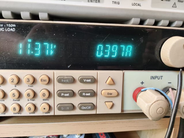
This is a load test of the fan driver circuit continuously outputting 400mA of current. As seen, the inductor heated up to 81.9°C.
![]()
![]()
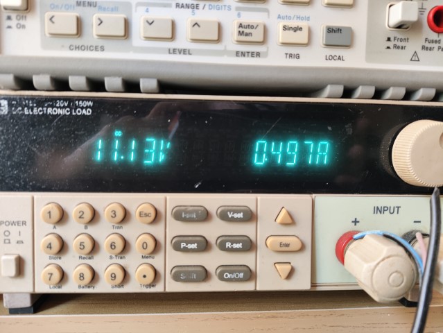
Finally, with a 500mA load current test, the inductor heated up to 87.4°C.
![]()
![]()
Even though the test results show that the Buce module's circuit pretty much meets the specs, it's interesting that the heat source isn't the tiny SOT-23-6 Buck regulator you'd expect, but the inductor.
You might think 87°C is bad for the circuit, but for a fan driver, it rarely runs at full power for long. Even if the circuit can handle it, your ears probably can't stand the fan noise.
Of course, there's still room for improvement in heat dissipation, so the next version will have a better PCB layout for better cooling and use a better inductor without changing the size.
-
Working on the carrier/driver board for my LED controller
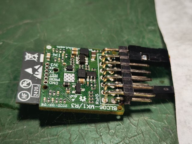
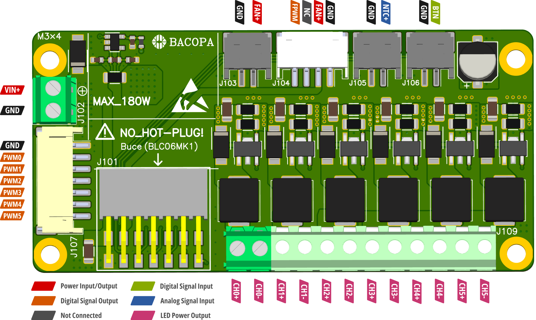
02/28/2025 at 04:33 • 0 commentsI just sent the design of the carrier/driver board to the PCB fab.
![]()
-
Just designed a 6-channel version
02/02/2025 at 03:17 • 0 commentsYou want a moon light channel? Now you got it.
As usual, all design source files are in github.com/oldrev/borneo
![]()
![]()
High-Power Smart WiFi Aquarium LED
The ultimate open-source aquarium LED and mobile app.