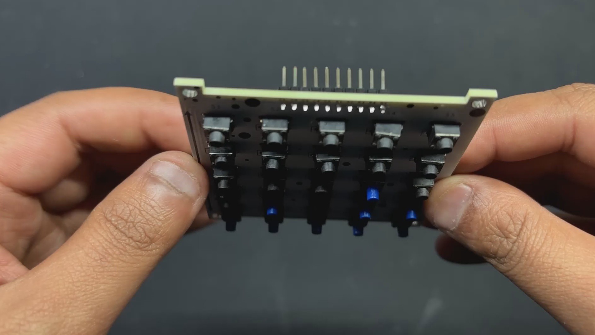
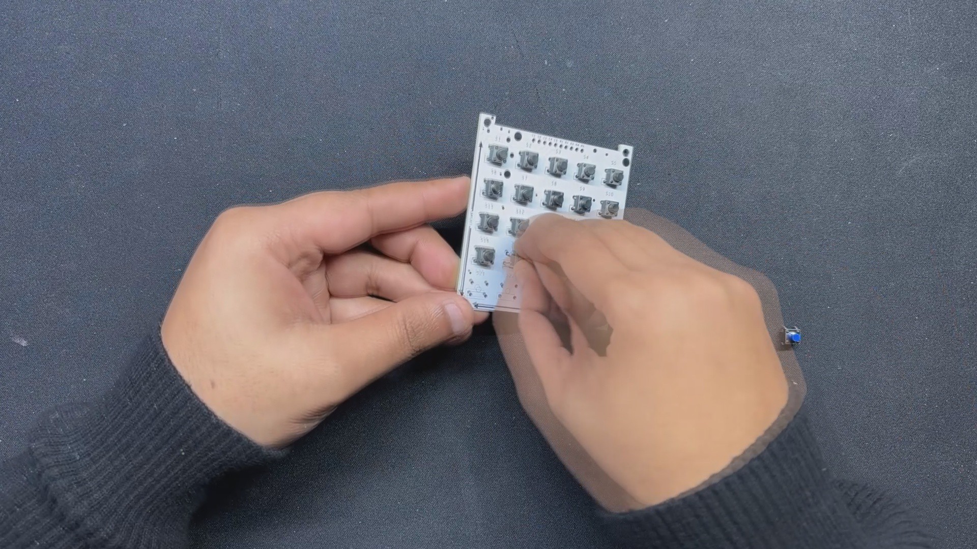
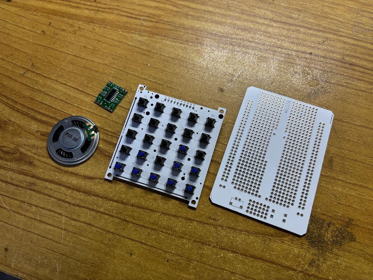
The assembly process begins with placing all 25 switches in their respective pads on the Matrix PCB; we are utilizing 6x6 Tacktile buttons here, and we must ensure that all buttons are correctly added to their pads, as some of the buttons' pins bend when placed in the footprint.
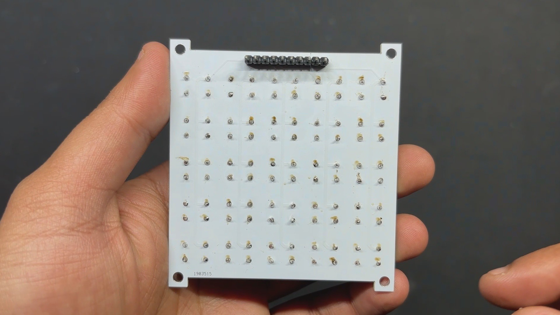
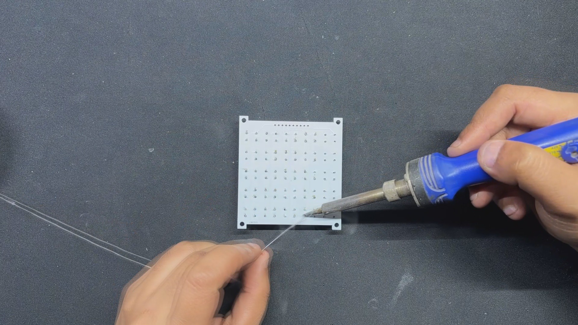
Next, we solder all of the switch pads on the bottom side of the board with a soldering iron.
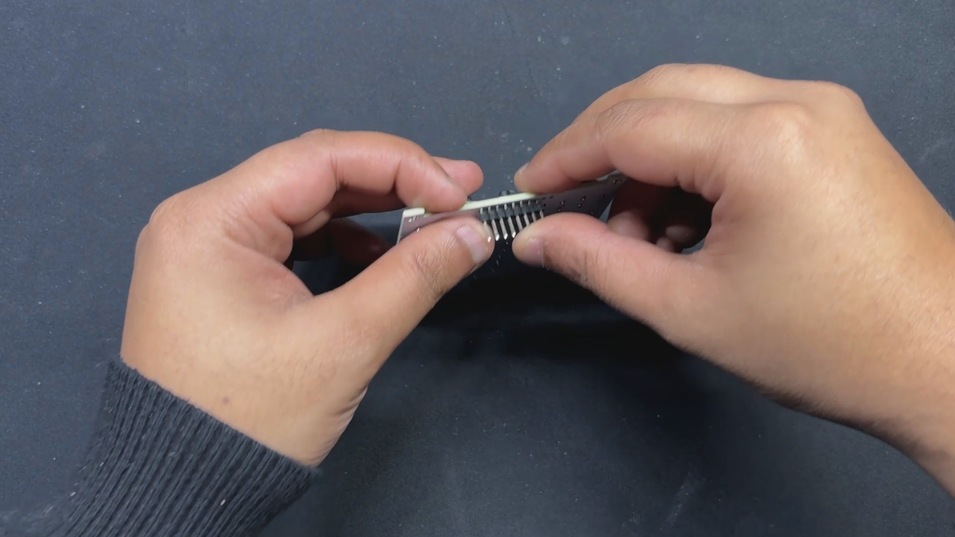
Following that, we place a CON10 male header pin in its place and solder its pads from the top side of the board.
Matrix Board is now assembled.
2
WIRING
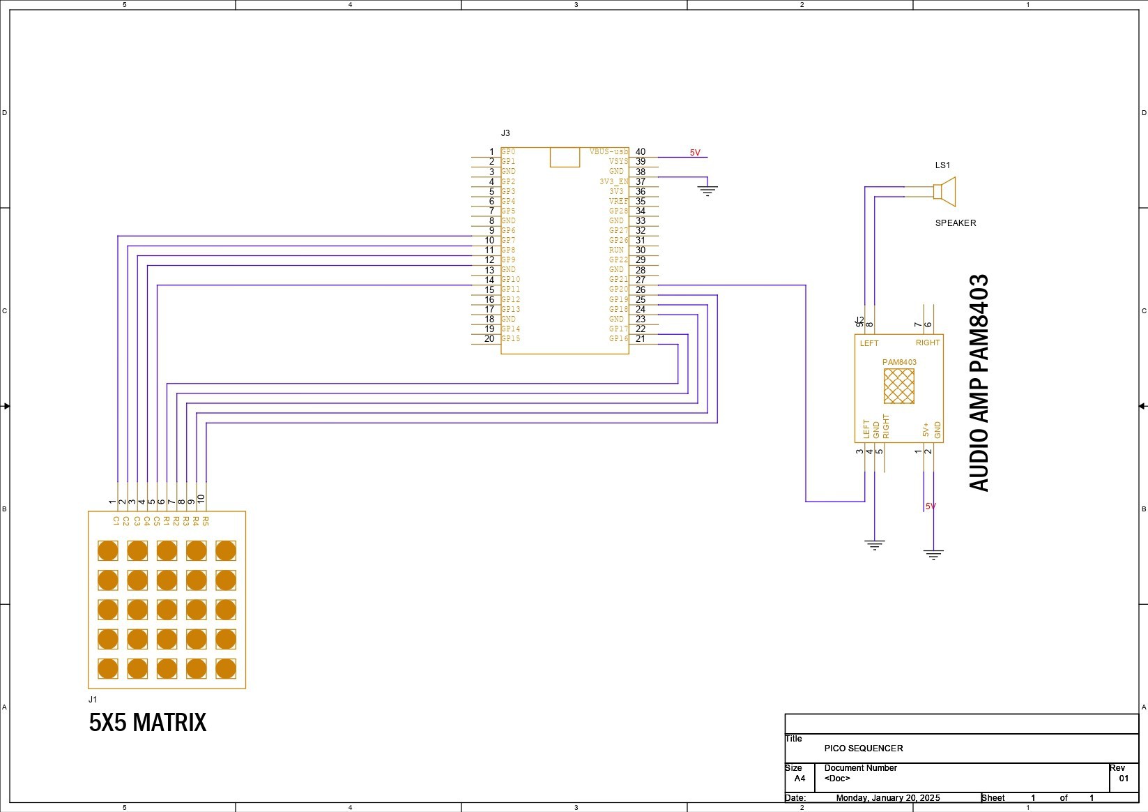
In terms of wiring, we linked the column pins of our matrix keyboard (C1-C5) to GPIO6, GPIO7, GPIO8, GPIO9, and GPIO10. From R1 to R5, the row pins are connected via GPIO16, GPIO17, GPIO18, GPIO19, and GPIO20.
The speaker output pin is GPIO21, which is connected to the audio amplifier's L input. The 5V pin of the audio amplifier is linked to the PICO's VBUS, while GND is connected to GND. The speaker is attached to the audio amplifier's left output.
A simplified schematic is attached if you want to recreate the circuit.
3
CODE
Here's the code we used.
#include<Wire.h>// Define keypad pinsconstint rows = 5;
constint cols = 5;
constint rowPins[rows] = {16, 17, 18, 19, 20}; // Updated row pinsconstint colPins[cols] = {6, 7, 8, 9, 10}; // Updated col pins// Define frequencies for buttonsconstint frequencies[5][3] = {
{110, 123, 146}, // Row 1
{164, 196, 220}, // Row 2
{246, 294, 330}, // Row 3
{349, 392, 440}, // Row 4
{494, 523, 587} // Row 5 (last button will be for record)
};
// Pin for speakerconstint speakerPin = 21;
// Recording variablesbool isRecording = false;
unsignedlong sequence[100];
int sequenceIndex = 0;
// Button coordinatesconstint recordRow = 4;
constint recordCol = 2; // Last button in Row 5constint delayRow = 4;
constint delayCol = 1; // Second to last button in Row 5voidsetup(){
Serial.begin(115200);
// Initialize row pins as inputsfor (int i = 0; i < rows; i++) {
pinMode(rowPins[i], INPUT_PULLUP);
}
// Initialize column pins as outputsfor (int i = 0; i < cols; i++) {
pinMode(colPins[i], OUTPUT);
digitalWrite(colPins[i], HIGH);
}
// Initialize speaker pin as output
pinMode(speakerPin, OUTPUT);
Serial.println("Setup complete.");
}
voidplaySound(int freq){
tone(speakerPin, freq, 200); // Play sound on pin 21 for 200ms
Serial.print("Playing sound at frequency: ");
Serial.println(freq);
}
voidplaySequence(){
for (int i = 0; i < sequenceIndex; i++) {
playSound(sequence[i]);
if (digitalRead(rowPins[delayRow]) == LOW && digitalRead(colPins[delayCol]) == LOW) {
delay(750); // Add delay if delay button is pressed (adjust as needed)
} else {
delay(250); // Default delay between notes in the sequence
}
}
}
voidloop(){
for (int i = 0; i < cols; i++) {
digitalWrite(colPins[i], LOW); // Activate column ifor (int j = 0; j < rows; j++) {
if (digitalRead(rowPins[j]) == LOW) { // Button press detectedif (i == recordCol && j == recordRow) { // Check if it's the record buttonif (isRecording) {
isRecording = false;
Serial.println("Recording stopped. Playing sequence...");
tone(speakerPin, 880, 500); // Play tone to signal recording stop
delay(500); // Delay to avoid multiple triggers
playSequence(); // Play recorded sequence
} else {
isRecording = true;
sequenceIndex = 0;
Serial.println("Recording started...");
tone(speakerPin, 440, 500); // Play tone to signal recording start
delay(500); // Delay to avoid multiple triggers
}
} elseif (!(i == delayCol && j == delayRow)) { // First 10 buttons for tones, excluding delay button
playSound(frequencies[j][i]);
if (isRecording) {
sequence[sequenceIndex] = frequencies[j][i];
sequenceIndex++;
Serial.print("Recording note: ");
Serial.println(frequencies[j][i]);
}
}
delay(200); // Debounce delay
}
}
digitalWrite(colPins[i], HIGH); // Deactivate column i
}
}
This test sketch utilises the 5x5 matrix keyboard to generate bass tones, record sequence, and add time delay during playback.
The code iterates through each column, setting it LOW to activate it, and then checks each row for a button press; if a button press is detected, it identifies the button based on its row and column position.
When the record button (located at `recordRow` and `recordCol`) is pressed, it toggles recording mode; if recording mode is active, each button press stores the corresponding frequency in the sequence array, and pressing the record button again stops recording and plays back the recorded sequence.
4
RESULT
This small build resulted in a functioning Sequencer-Synth capable of recording and playing music, thanks to the Mighty Raspberry Pi PICO 2 and our unique 5x5 button matrix.
By pressing any button, a tone is generated. When the record button is hit, recording mode is activated; if recording mode is active, each button press saves the corresponding frequency to the sequence array, and pushing the record button again stops recording and replays the recorded sequence.
A little YouTube short is added so you can see how nicely this device functions.
There are several improvements. This is only a test device made from spare parts from earlier projects assembled on a prototyping board; the next iteration will have a better formfactor and additional buttons, possibly quiet ones, as we discovered a sound issue while pressing the buttons. We will also include an OLED panel that will show which tone is pressed and what tones are being recorded, as well as a few other functions.
Leave a comment if you need any help regarding this project. This is it for today, folks, and stay tuned for the calculator project update.
Special thanks to Seeed Studio Fusion Service for supporting this project. You guys can check them out if you need great PCB and stencil service for less cost and great quality.
And I'll be back with a new project pretty soon, peace.
 Arnov Sharma


Discussions
Become a Hackaday.io Member
Create an account to leave a comment. Already have an account? Log In.