Jeremy
-
Optimized version
02/05/2025 at 23:34 • 0 commentsI learned from a bunch of mistakes on my first version, and it moves so much better! I'll explain all the changes, but first, take a look!
---------- more ----------Coil width
Only after painstakingly winding the coils on my first version I realized I had made some miscalculations, and each coil was 1mm too wide. The six coils are arranged into two groups of A, B, and C. The width of the coils needs to line up with the arrangement of the magnets so that there is the same magnet alignment in the first group of coils and the second. If this is wrong, the magnets will only line up with one group at a time, and the movement will be jumpy.
In this version, the coils are 2.6mm wide, with 0.8mm separators between them. This lines up with each magnet pair being 6.35mm wide, separated by 4mm spacers.
MAGNET PAIR + SPACER = (COIL + COIL SEPARATOR) * 3
The width of one magnet pair and a magnet spacer should equal the width of three coils and coil separators.
Coil Fabrication
The other problem with the first version was I had 3D printed a single coil spool bobbin with separators for all six coils.
![]()
On paper, this seems like a great idea. You can precisely control the width of all the coils, and they'll be perfectly aligned. The problem comes when you've wound all six coils, and a wire on one of the coils breaks. Now, you have to start over fresh.
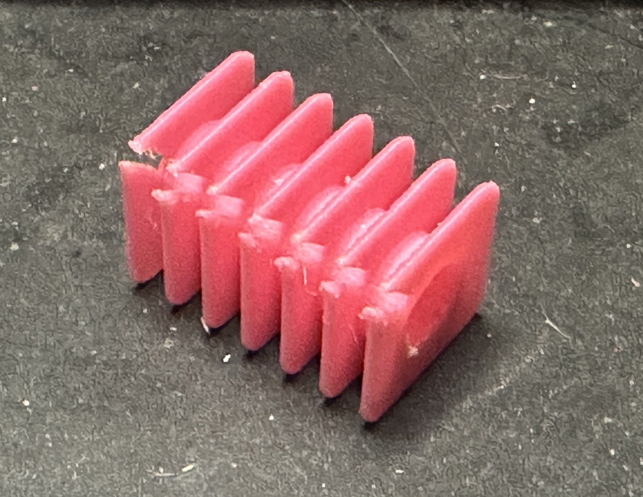
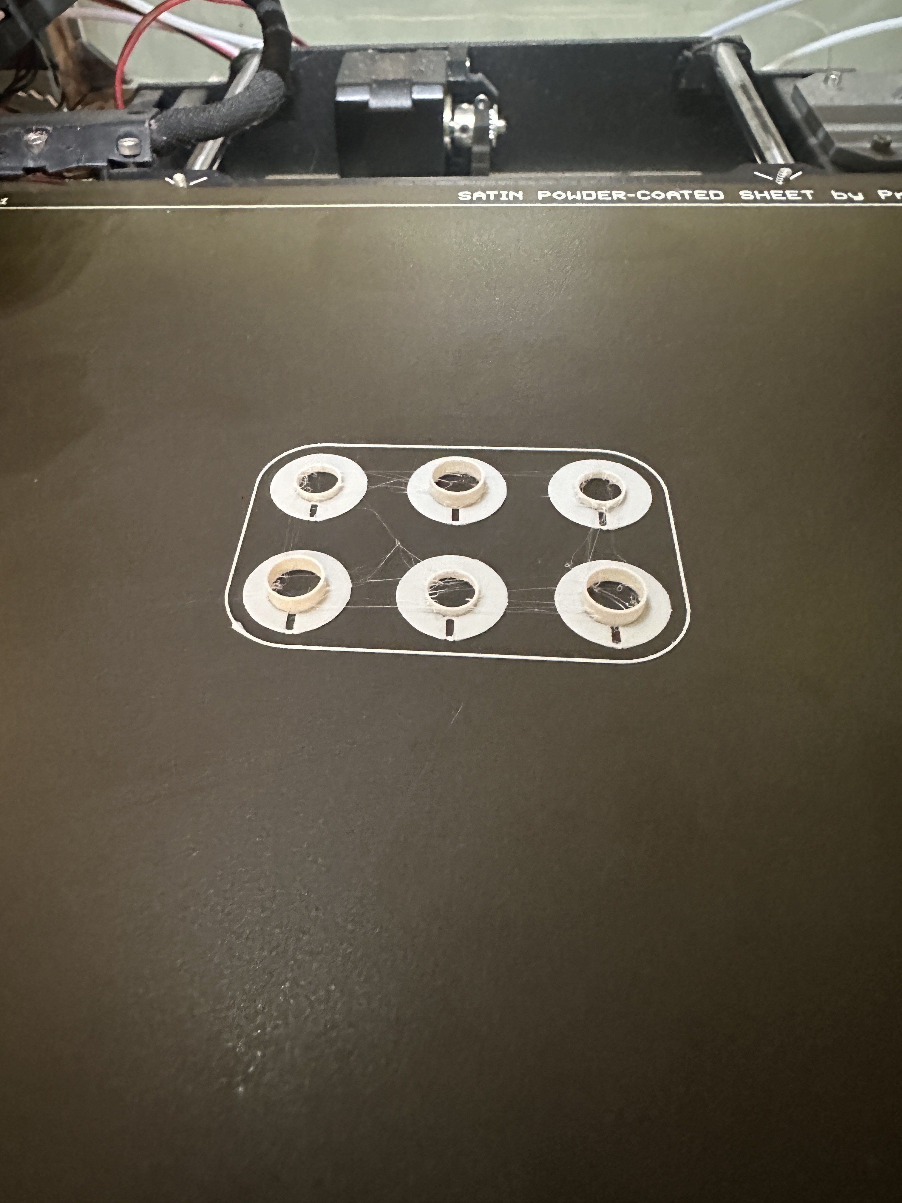
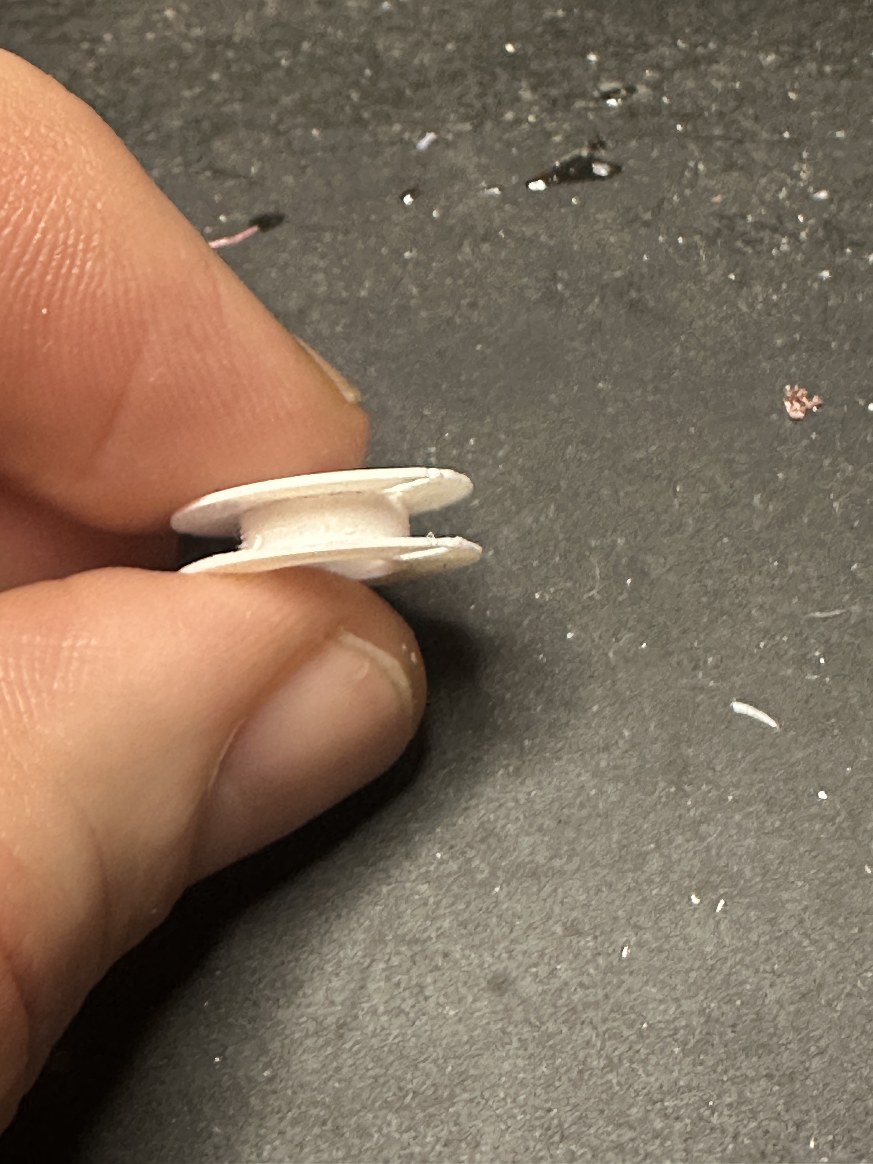
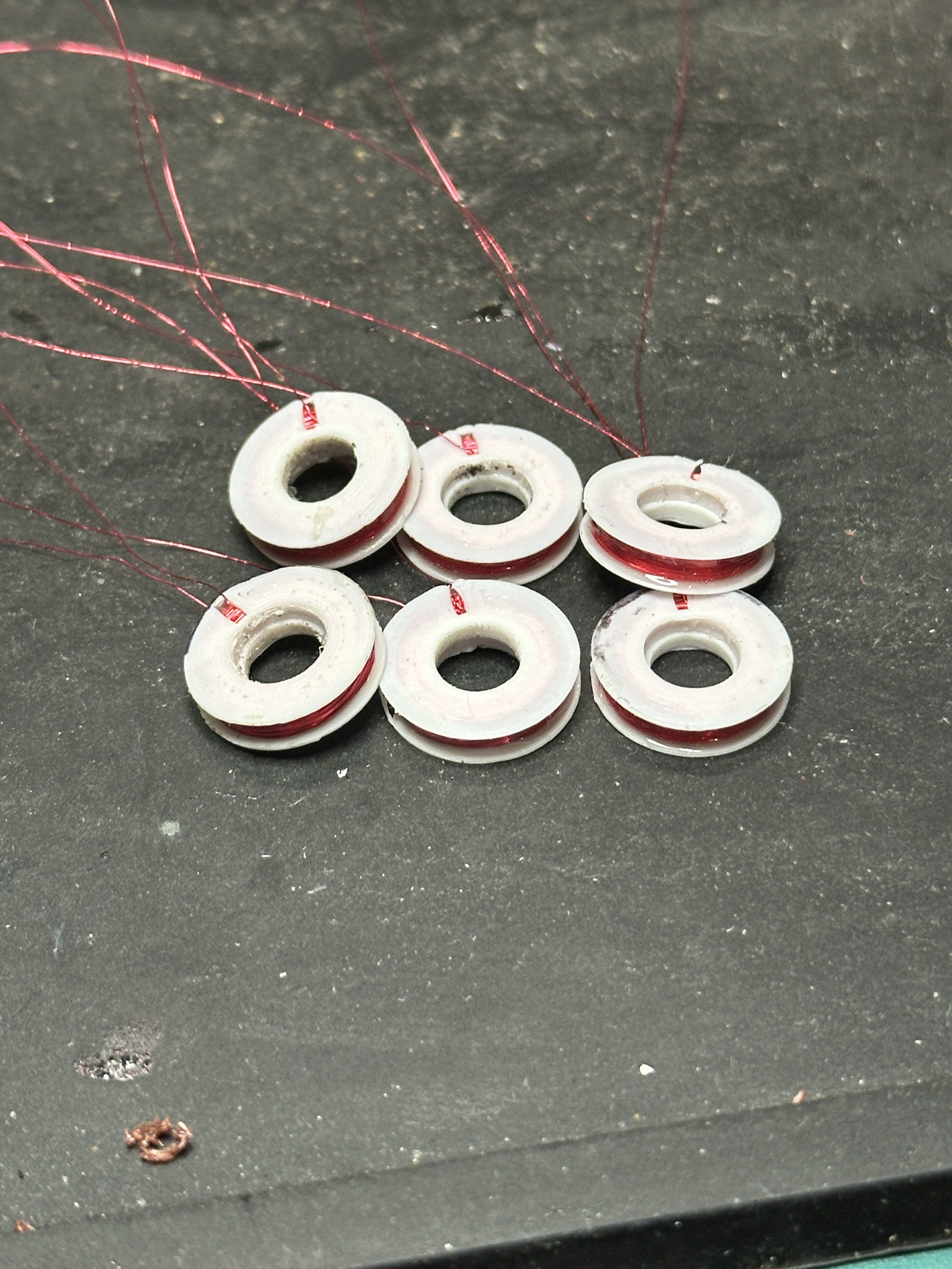
For this version, I decided to wind each coil independently. To easily print without worrying about overhangs or support, I designed each bobbin to be printed as two pieces whose tubes would nestle together into a single bobbin. You can find the 3D printable files in the github repo.
![]()
![]()
![]()
![]()
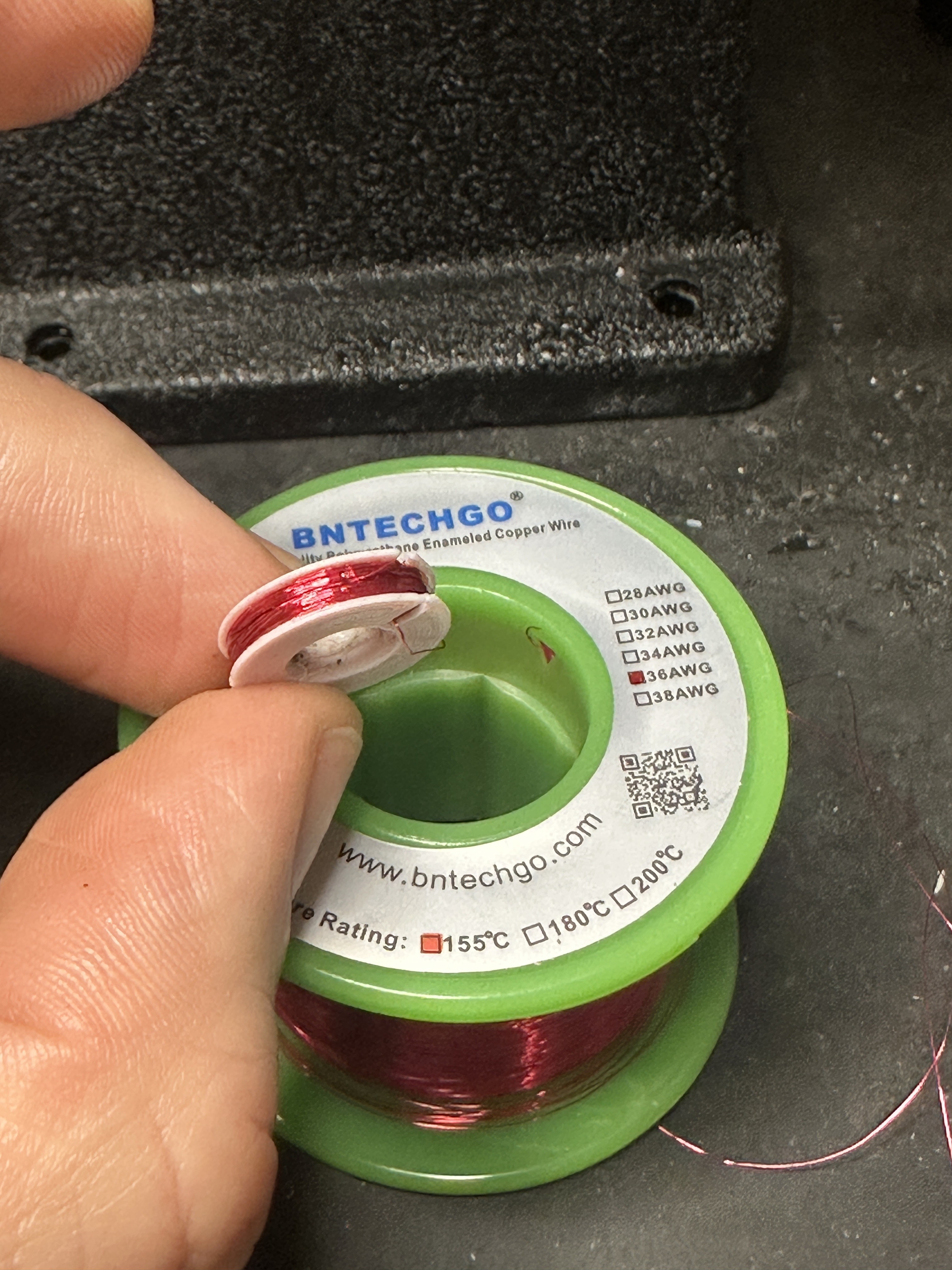
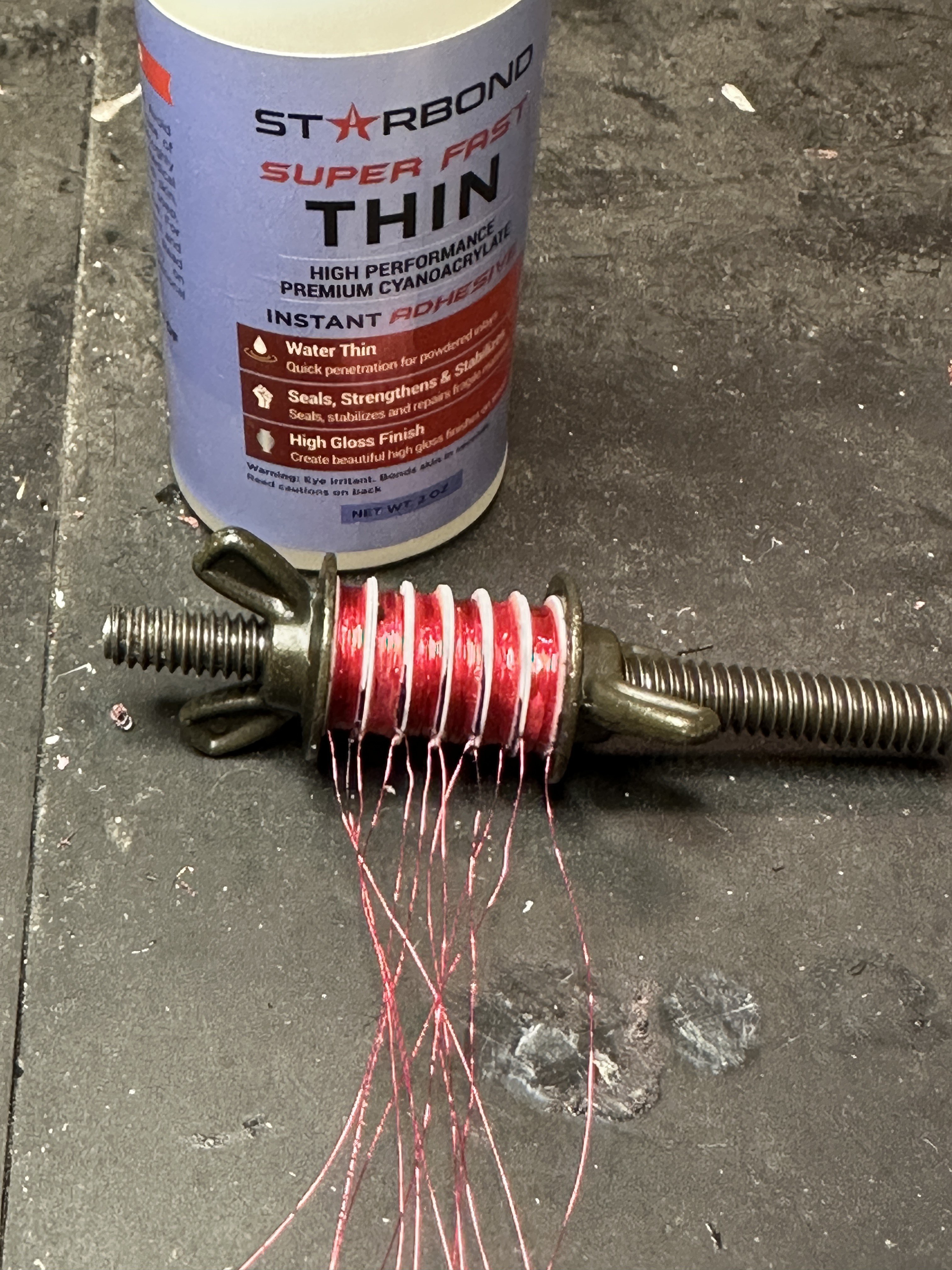
I gave each coil 300 turns of AWG 36 magnet wire, and then I added a layer of epoxy around the coils to secure the wires. To combine them into a single unit, I hit them with superglue and clamped the whole thing on a threaded rod with wingnuts and washers.
![]()
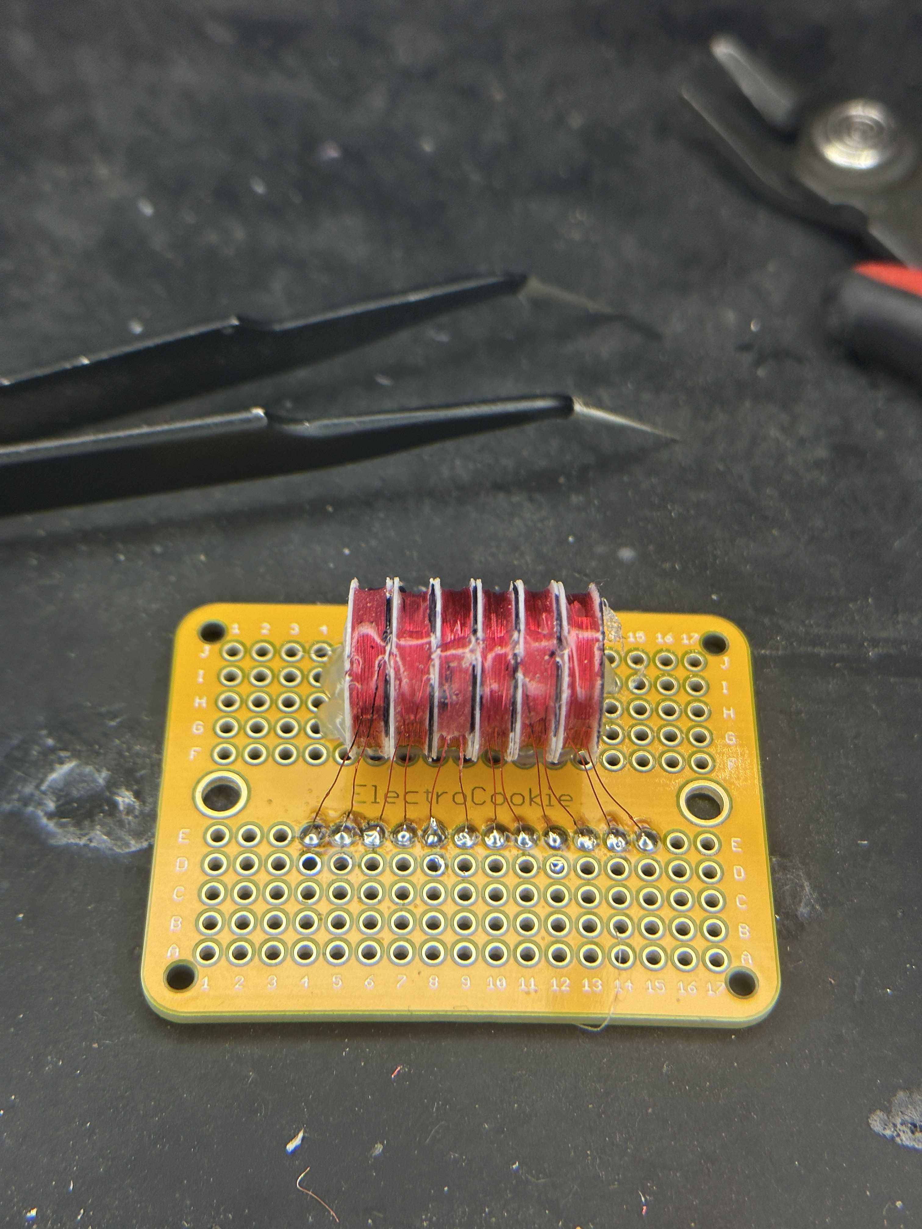
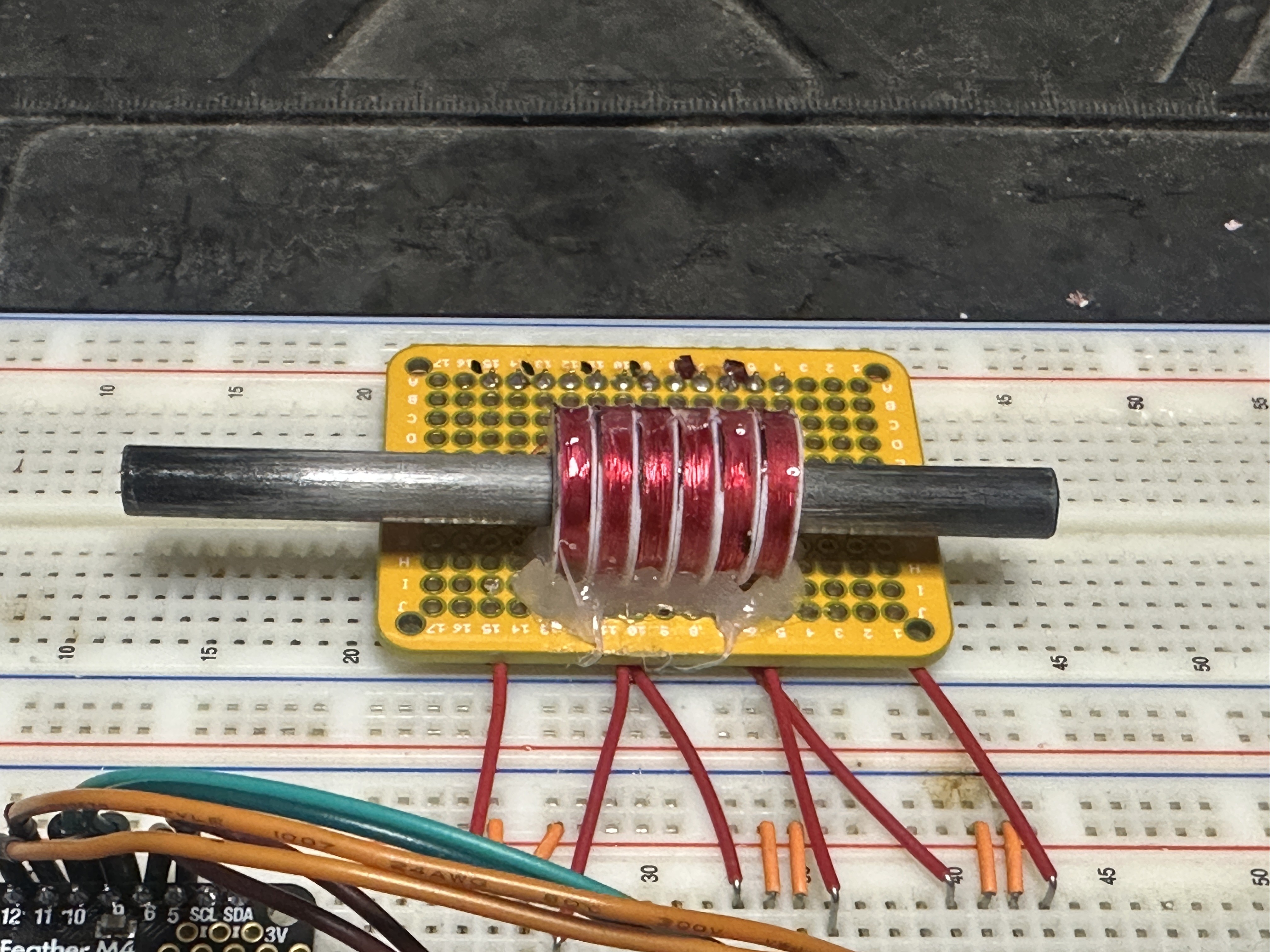
Lastly, I hot glued the assembly onto a perf board and soldered the wires into place.
![]()
![]()
Each coil is about 16Ω, and I wanted the flexibility of powering the coils up to 6v, so I connected each pair of coils together. A/A', B/B', and C/C'. It's important that the second coils (denoted with the apostrophe) need to be in reverse polarity with the first coils. To achieve this, I connected the second coils in reverse of the first ones. For example, when looking at each coil, their wires are labeled from left to right as 1 and 2:
- Coi A, wire 1 -> Motor driver output OA
- Coil A, wire 2 -> Coil A', wire 2
- Coil A', wire 1 - Motor driver output OA
This wiring arrangement should swap the magnetic polarity of the second coil.
Code
Original sine wave program
After all this, the movement still wasn't great. It was jumpy and sometimes moved backward for a step before jumping forward. The original program used three sine waves, each offset by 120 degrees from the other, to determine the current for each phase at each step (see my explanation in my last post),
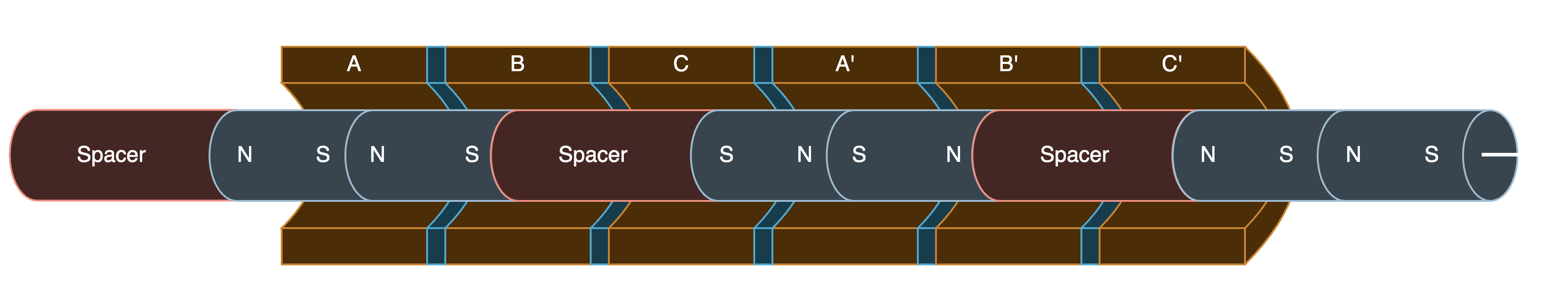
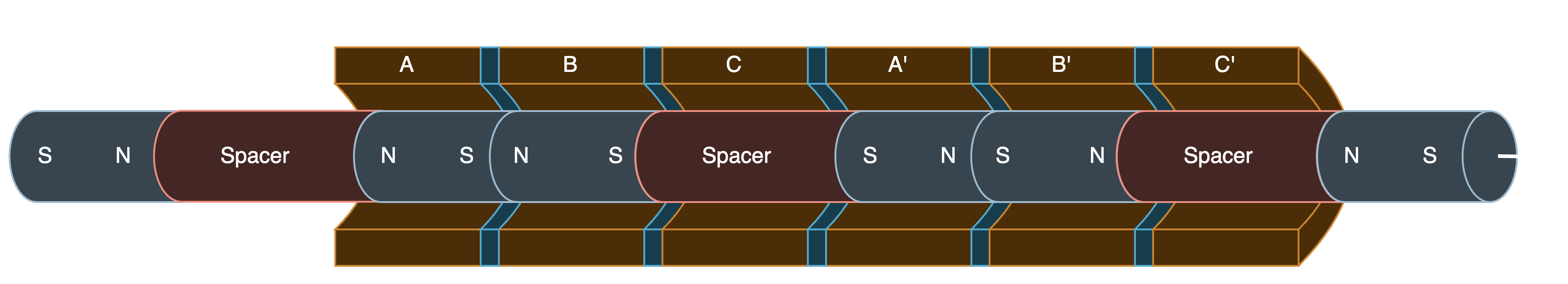
But here's the problem: look at phases C and A' in these two steps:
![]()
![]()
In the second step, the pusher is supposed to move toward the right and align the magnets under A/B and A'/B'. But, phase C' is at -100%, which likely pulls the pusher back to the left. In the step after this, B' becomes -100%, and C' is reduced to -50%. This then jumps the pusher back towards the right.
I spent a lot of time researching how to recalculate the curves to avoid this. I could never figure it out, so please let me know if anyone else has the answer.
In the end, I went with a different approach...
PWM lookup table
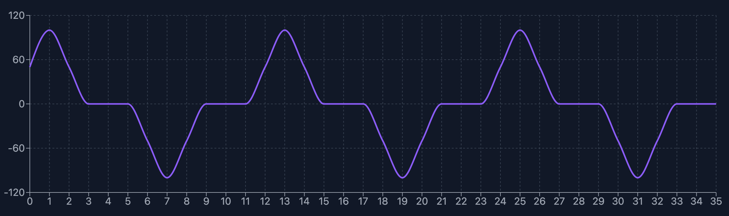
In this program, I created a lookup table of the current output for each phase, for each step, from -100% to +100% in 25% increments for a complete cycle. The program then interpolates phases between each step to smooth the motion. For the video at the top, the program makes 10 steps for each step in the lookup table.
STEPS = [
  [25, 0, -75 ],
  [50, 0, -50 ],
  [75, 0, -25 ],
  [100, 0, 0 ],
  [75, 25, 0 ],
  [50, 50, 0 ],
  [25, 75, 0 ],
  [0, 100, 0 ],
  [0,  75, 25 ],
  [0, 50, 50 ],
  [0,  25, 75 ],
  [0,  0, 100 ],
  [-25,  0, 75 ],
  [-50, 0, 50 ],
  [-75, 0, 25 ],
  [-100, 0, 0 ],
  [-75, -25, 0 ],
  [-50, -50, 0 ],
  [-25,  -75, 0 ],
  [0, -100, 0 ],
  [0, -75, -25, ],
  [0, -50, -50 ],
  [0, -25, -75 ],
  [0, 0, -100 ],
]
As you can see, each coil is completely off for 20% of its cycle. Graphed, the curve roughly looks like this for each coil.
![]()
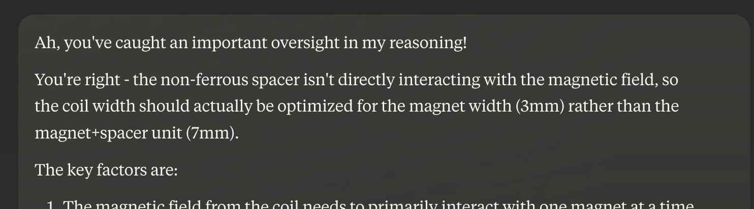
Force output
The force output of the actuator is still quite small. I haven't measured it, but it's easy to stop the pusher with my finger with almost no force at all.
-
First working version - How it works
01/31/2025 at 23:20 • 0 commentsIt moves!
It's not pretty, but it works! The movement is a little bouncy. After recalculating things, it appears that the coils are too wide, which likely causes the magnets to be slightly out of alignment (more on that later) and causes the movement to bounce.
---------- more ----------General Actuator Design
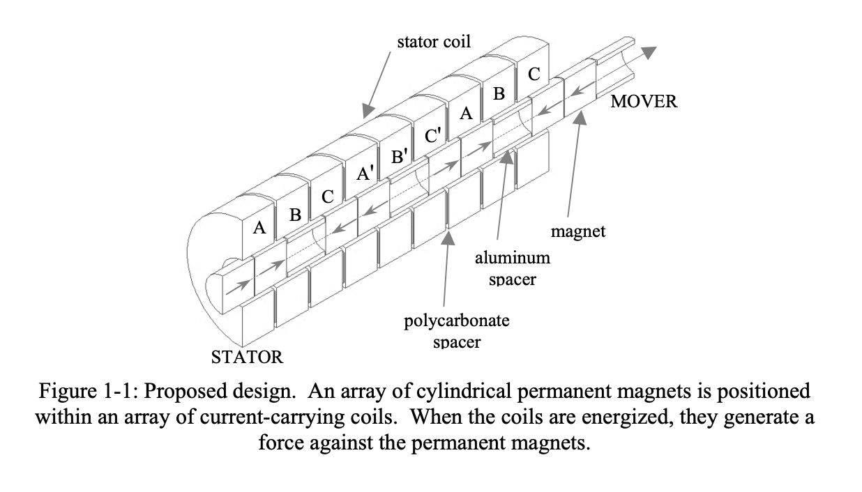
I adapted the design from a thesis from Texas A&M titled "Design and Construction of a Precision Tubular Linear Motor and Controller" (source).
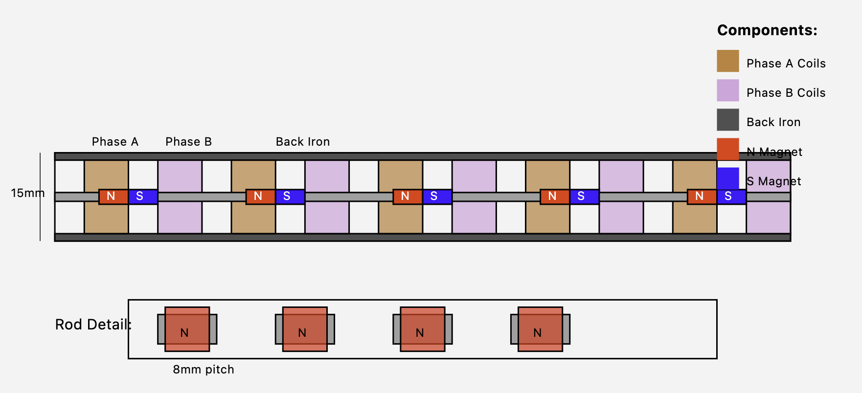
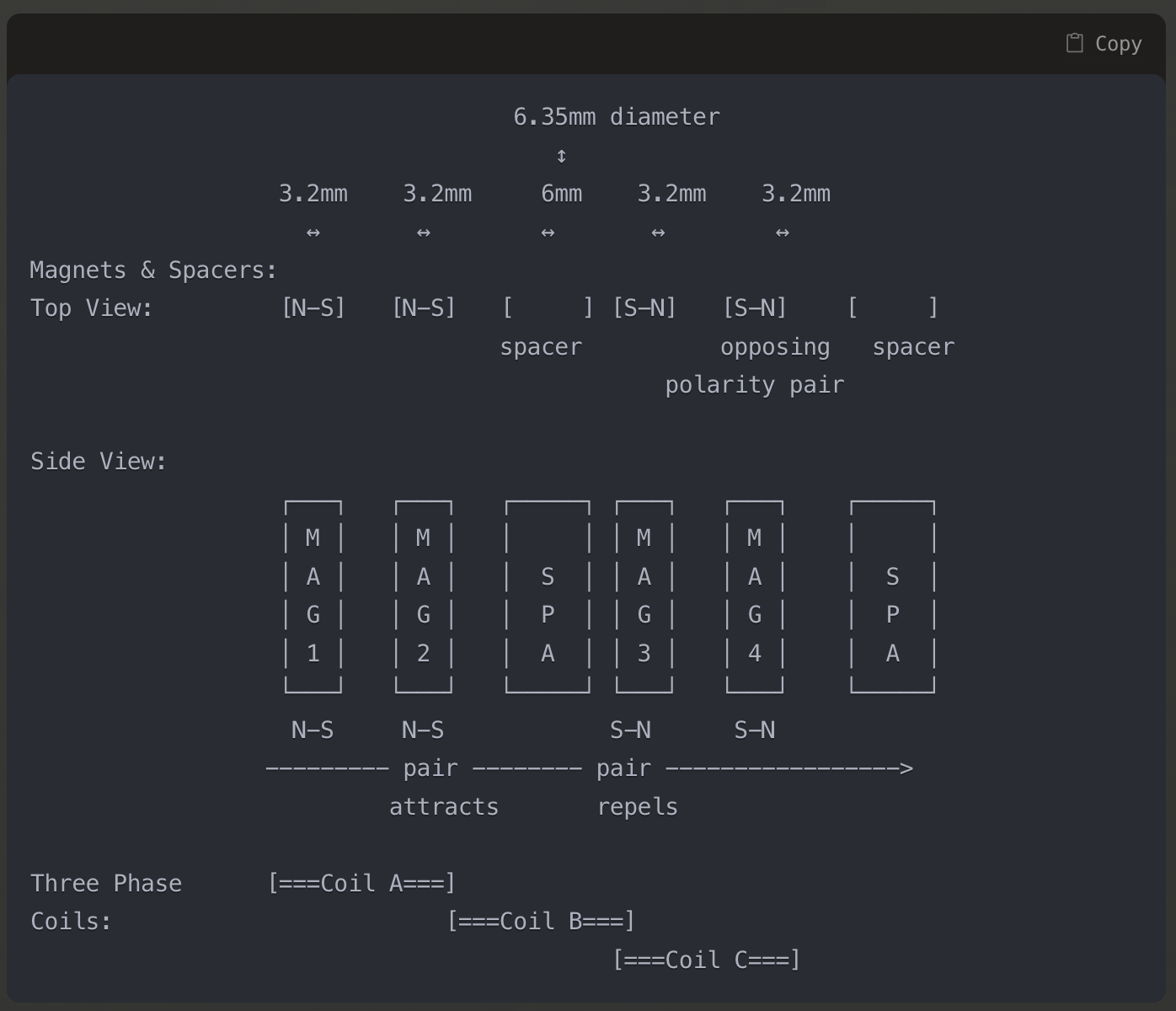
In the design, there is a tube (the pusher) filled with pairs of permanent magnets, with like poles facing each other ( NS-NS—SN-SN), and a spacer between them. The magnet pairs repel each other, yielding greater magnetic field intensity.
The pusher is moved by six coils, divided into 3 phases: A, B, and C. The second coil of each phase is in reverse magnetic polarity. We denote this with an apostrophe added to the phase labels: A', B', and C'.
![]()
For example, coils A and A' are connected to the same power output, but the wires of A' are connected in reverse. Both will always have the same current flowing through them, but their magnetic fields will be in opposite orientations.
A part of the thesis that I spent way too much time re-reading was this gem:
"the pitch of six magnets with six spacers is 63.30 mm, twice the pitch of two magnets with one spacer"
I'm not sure why it was worded this way, but it's basically saying: "three coils + three coil spacers = two permanent magnets + their spacer".
![]()
Dimensions of the linear motor in the thesis paper (my linear motor uses different dimensions) This is the pitch and ensures that the magnets aligned in A/B/C are arranged the same, but opposite polarity, in A'/B'/C'. If the pitch is different, the movement and force will be affected. This is likely why my current version has bouncy movement and low force.
Moving the pusher
The current is shifted from one coil to another to move the pusher. To calculate the current for each movement step, we generate a sine curve for each phase at 120 degrees apart.
![]()
As I understand it, here's how it looks when moving the actuator pusher.
[EDIT: I might be off on how the stepping works, below. I discuss that in my next post]Step 0°
The first step
![]()
At this step, phase A and A' are at 100% and -100% current, respectively. The other phases are at +-50%. In this case, the pairs of magnets are centered under A and A'.
Step 60°
![]()
Now, A/B phases are at +-50%, and the magnet moves to the right to center between these two coils.
Step 120°
![]()
B is at +-100%, and the magnets move to be under it.
Step 180°
![]()
Phases B & C are at +-50%, and the magnets move to be centered between these two coils.
And so on, and so forth, to continue moving the pusher.
My Linear Motor
Dimensions
My version of the linear motor is much smaller than the one in the thesis I'm basing it on. Here are my part dimensions:
- Magnets: (see note below) 6.35mm long, 4.7625mm diameter
- Magnet spacer: 4mm long
- Pusher tube: 6mm diameter carbon fiber tube.
- Coils: 3.6mm wide -- should have been 2.6 mm wide!
- Coil spacer: 0.8mm thick
- Wire: 36 AWG
NOTE: For the magnets, instead of pairing up magnets between spacers, I used a single 6.35mm magnet. This made assembly slightly easier, and they should work the same. In this configuration, the pitch would be calculated as one magnet + spacer = 10.35mm.
Circuit
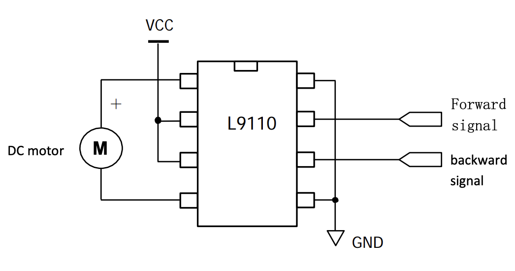
To drive the coils in both polarities (bipolar coil), we drive each coil with an H-bridge motor controller.
I used three L9110H H-bridge motor drivers, one driver per coil. These drivers have two inputs and two outputs.
![]()
From the datasheet. In this case, the motor is a coil phase. The outputs are connected to the wires of single-phase coils. The driver inputs determine the polarity of the output.
Input A Input B Output A Output B High Low High Low Low High Low High Low Low Low Low High High Low Low Microcontroller
At the center of the circuit is a microcontroller running CircuitPython. Each motor controller is connected to two of the microcontroller's PWM outputs.
Here's the code I used: https://github.com/jgillick/tubular-linear-actuator/blob/main/code/circuitpython/sine/code.py
-
The case for chat AI
01/23/2025 at 09:16 • 0 commentsWe've all been there. We want to learn a new technology for a specific application (for example, how to build a tubular linear motor) and have a million questions. We jump to google, read stack exchange, pop around forums, and get 100 little answers. Then, we have to wrap our head around all of them and try to create a cohesive picture. This can be a fun process but also challenging if the technology we're learning is outside our wheelhouse.
So, let me make the case for chat AI tools.
For this project, I came in understanding the basic principles of motors, but that's where my knowledge and experience ended; and I had a million questions. I started with Google and found the start of many answers, which also gave me more questions. The deeper I went, the more uncertain I was becoming at my task. So, I switched gears and took my questions to Anthropic's Claude AI.
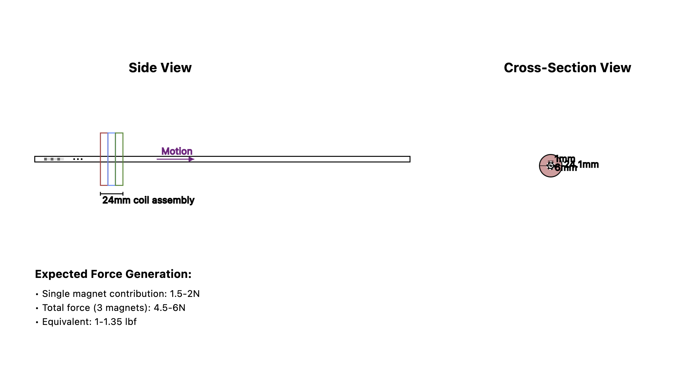
---------- more ----------But AI might give wrong answers!
I'm going to stop you right there. AI isn't a calculator and shouldn't be seen as such.
How many times have you asked someone a technical question, and they gave you the wrong answer?
Start by approaching AI as a knowledgeable person who has read the entire internet. Someone you're brainstorming with. They might not always have the correct answer, but they can likely get to it. Always be critical of the answers it gives you. If you don't understand something, ask it to explain why it works that way. If you think something is wrong, point it out. In my experience, when you point out mistakes, it'll usually correct itself immediately. Or it'll show you how it got to that answer. In the end, either way, you've probably learned something.
Here's an example of Claude correcting itself and then going into greater detail.
![]()
How is it for electronics?
What I love about Claude, is that it's not just text. Anytime it gives an answer where a diagram or simulation is helpful, it'll code it up and display it next to the conversation. It can also write runnable code that is cleaner than most example code I've seen online.
Diagrams and Charts
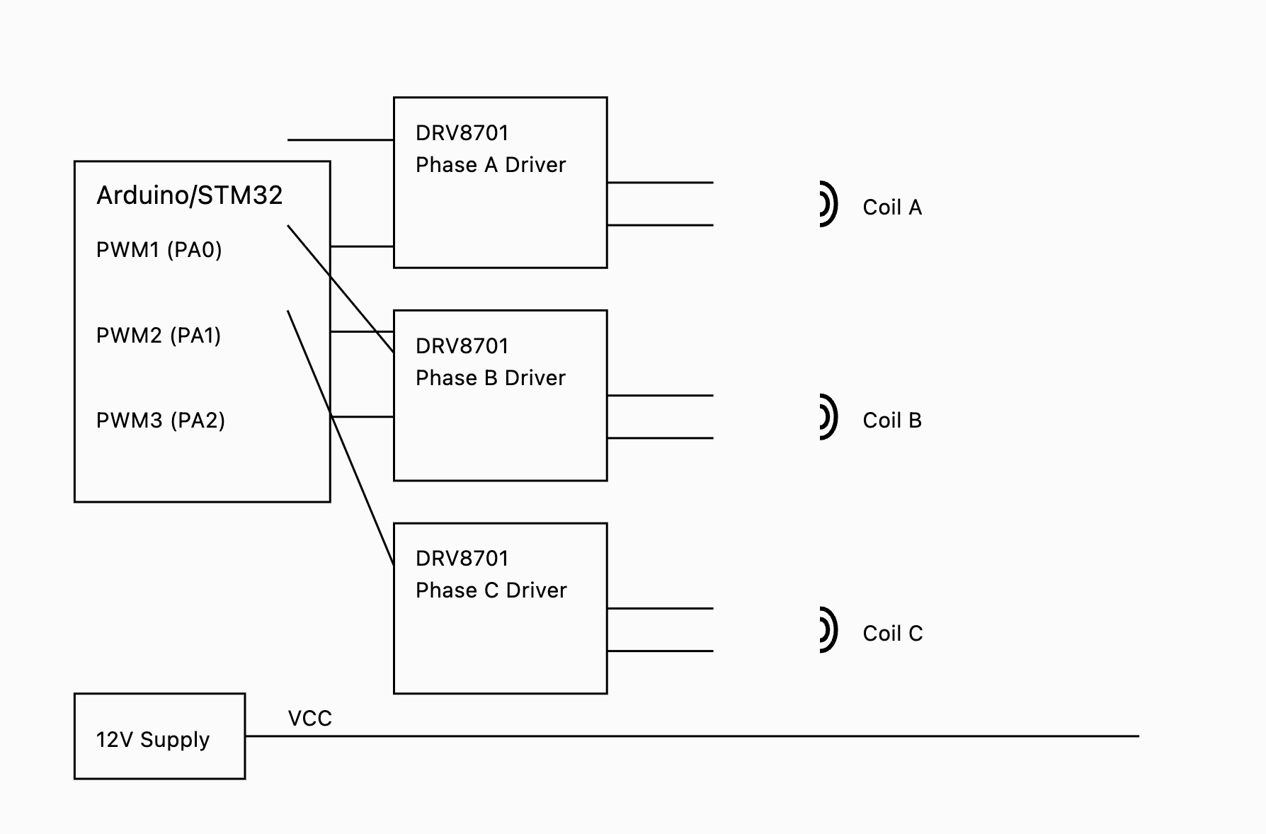
If you ask it to detail a physical thing, it'll draw you SVG diagrams with labels. It's not always perfect, but it usually gets the idea across.
![]()
![]()
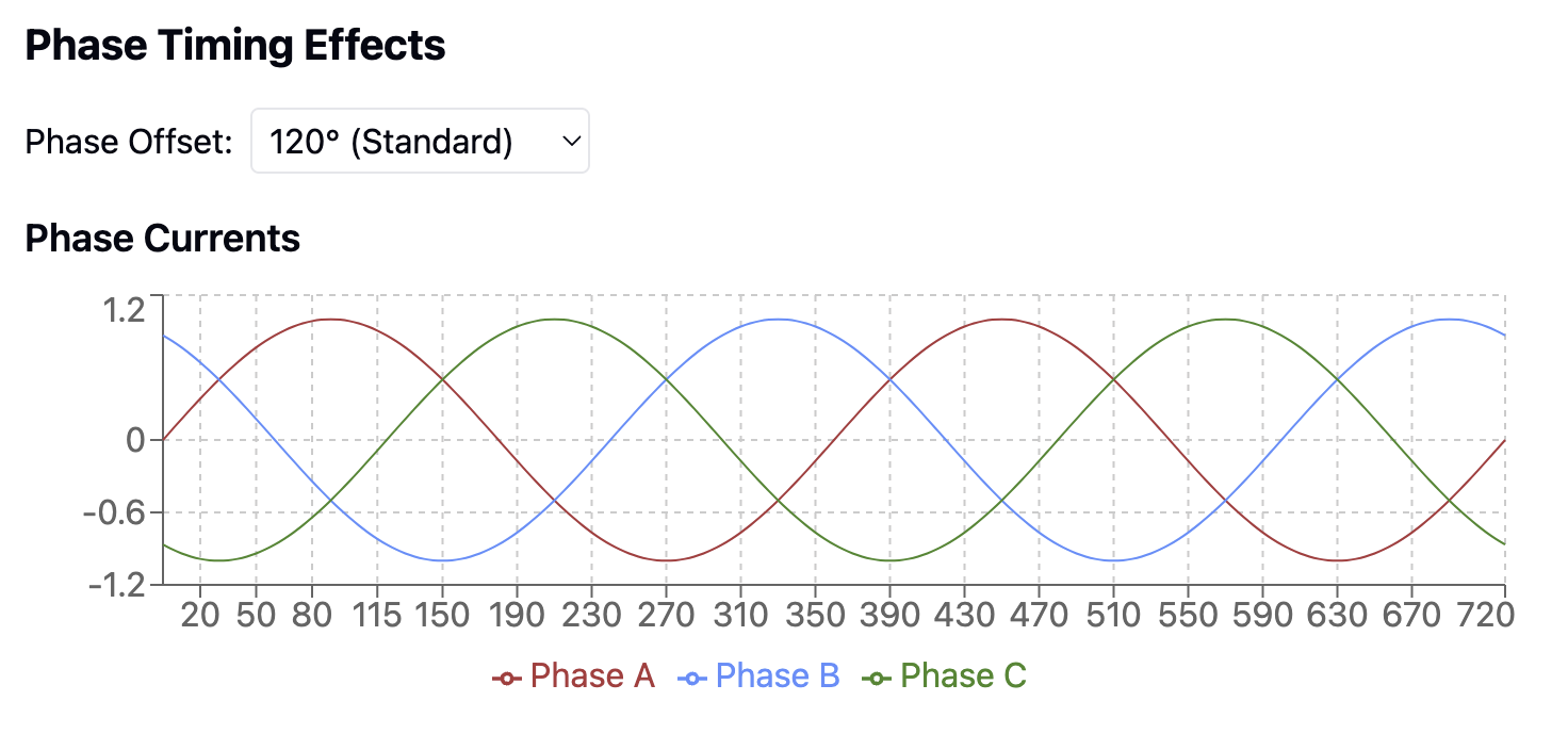
If you want to understand something like the electrical phases of a 3-phase motor, it'll graph it for you. In this case, it even included a dropdown menu to change the phase offset degrees.
![]()
Circuit Diagramming
This is where Claude's gears start to strip, and things get more confusing.
This first one is rough, but still got the idea across.
![]()
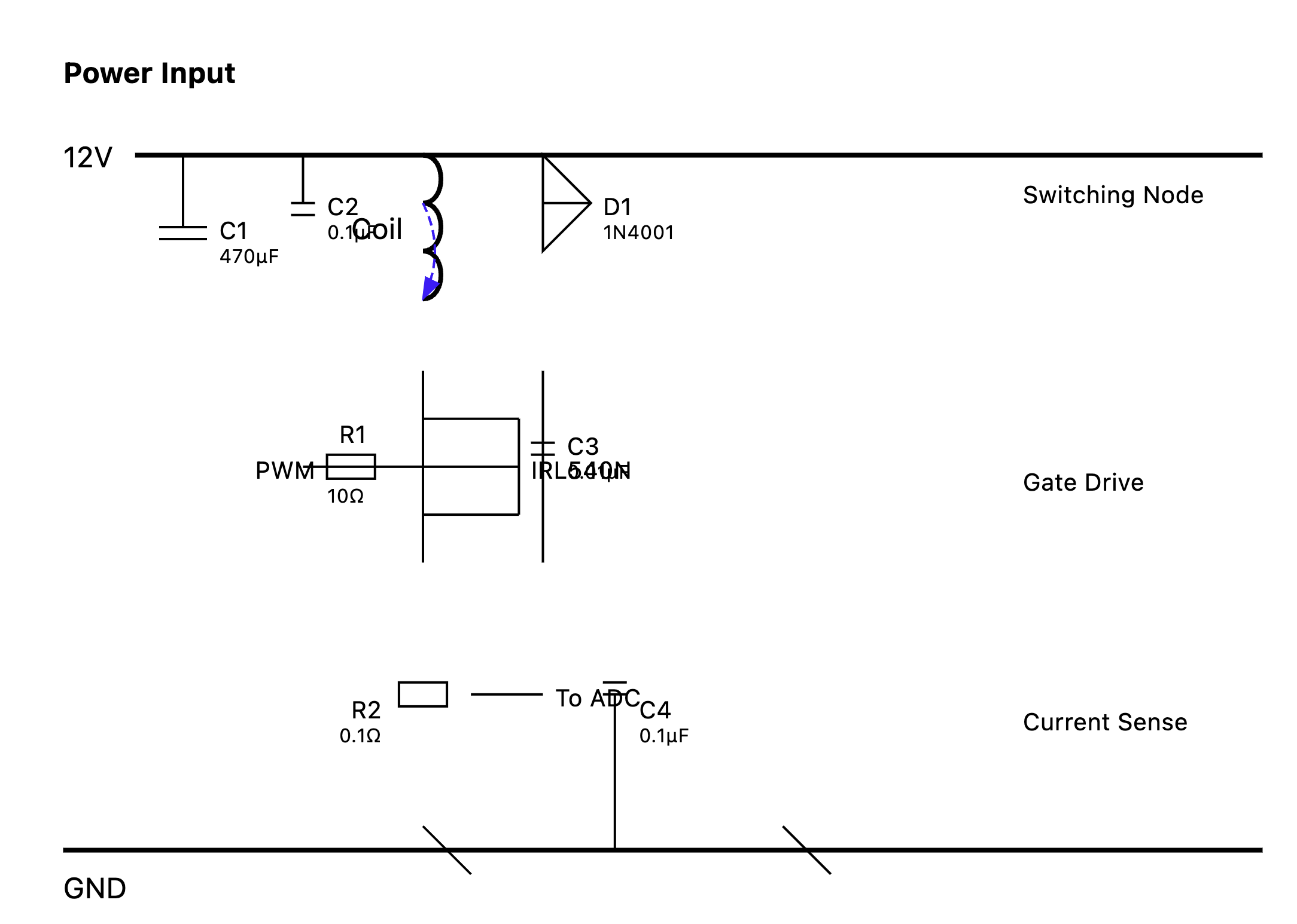
This next one looks like it's just throwing circuit symbols at the wall.
![]()
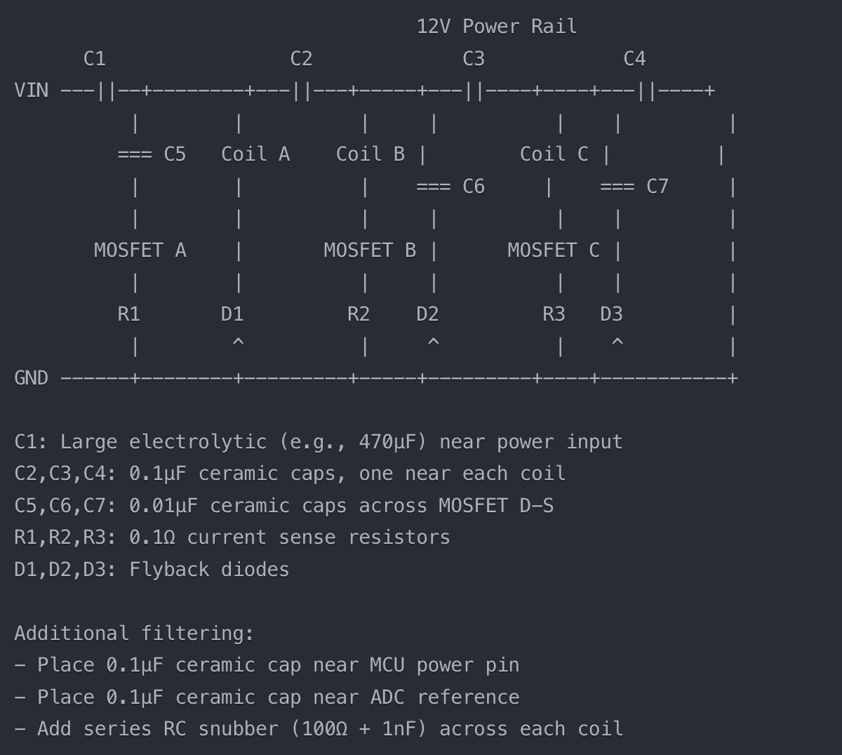
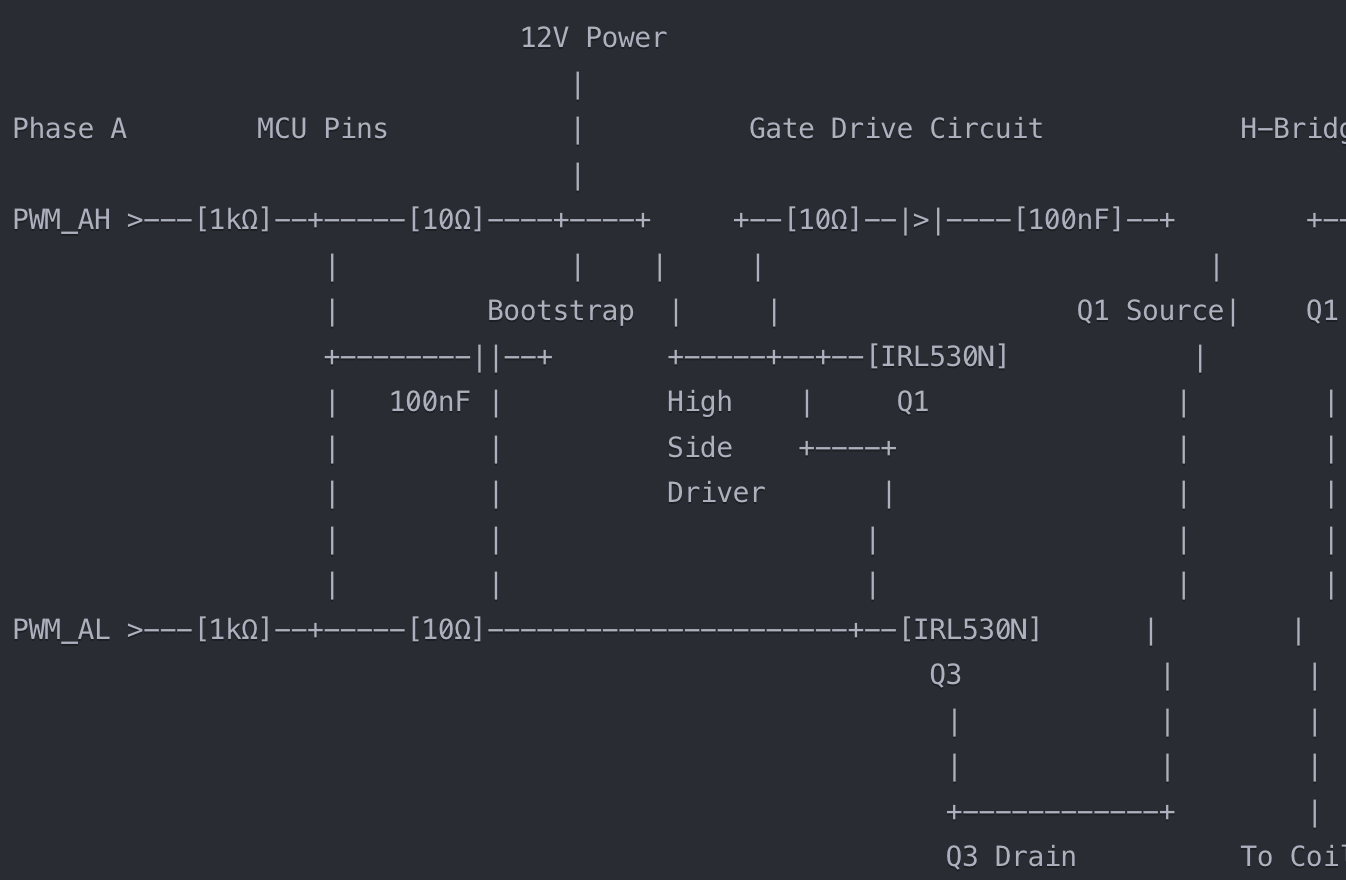
I've found that it's better at drawing circuit diagrams in ASCII. It's still not perfect, but it's better at visualizing the circuit concept.
![]()
This also works for other diagrams. For example, showing the physical arrangement of magnets and coils.
![]()
And still, sometimes, the ASCII diagrams just kinda fall over.
![]()
That said, even when it looks like it's randomly throwing symbols around, you can tell that it understands what it's trying to convey. This makes me feel confident that we're just scratching the surface, and as the AI models improve, so will their ability to draw complex circuit diagrams.
But isn't AI stealing other people's work?
I can understand this argument for AI that generates art, but I don't think it applies the same to science and engineering. Most of the circuit diagrams and engineering knowledge the AIs are learning are likely from open-source or public knowledge sources. Sure, there's a chance AI recommends something protected by patents or other trade laws, but this brings me back to my original point about ensuring you understand what AI is telling you.
And, to double down on this, looking through the lens of open hardware, the more we share our knowledge, the better we will all be.
Real Example
A big part of this project will involve hand-winding coils for the actuator. My first experiment resulted in coils that didn't have enough resistance on their own and would have created a short to the power supply. So, for the next coils, my question was: "how do I determine an appropriate wire gauge and number of winds to create the optimal resistance and force?"
For some of you, the answer to this might seem elementary.
I first went to Google. I assumed this would be a simple question with a simple answer. Ideally, there would be an online calculator or worksheet that I could use to generate this.
The process went like this:
- Forum: "Before we can calculate the wire gauge, we first need to know how many feet of wire you need."
- Me: "I'm not sure how many feet I plan to use. How would I know that?"
- Forum: "Well, how many winds do you need?"
- Me: "I don't know that either. In my case, the coil needs to be 3.6mm wide and wound around an 8mm shaft. I could use 50 winds or 500 or more."
- Forum: "How strong do you need the magnet to be in Teslas?"
- Me: "In what? Huh, I guess I need to figure out what that means, and how that applies to an air gap coil, and how that would interact with a permanent magnet." <brain explodes>
I'm someone who learns best while being hands-on, with positive momentum. The best way to get my learning dopamine flowing is by starting with a mostly functional answer and then figuring out the details later as I dig deeper into the project. These forums were taking the opposite approach (which is fine for some), which is to understand the academic parts first and then build it.
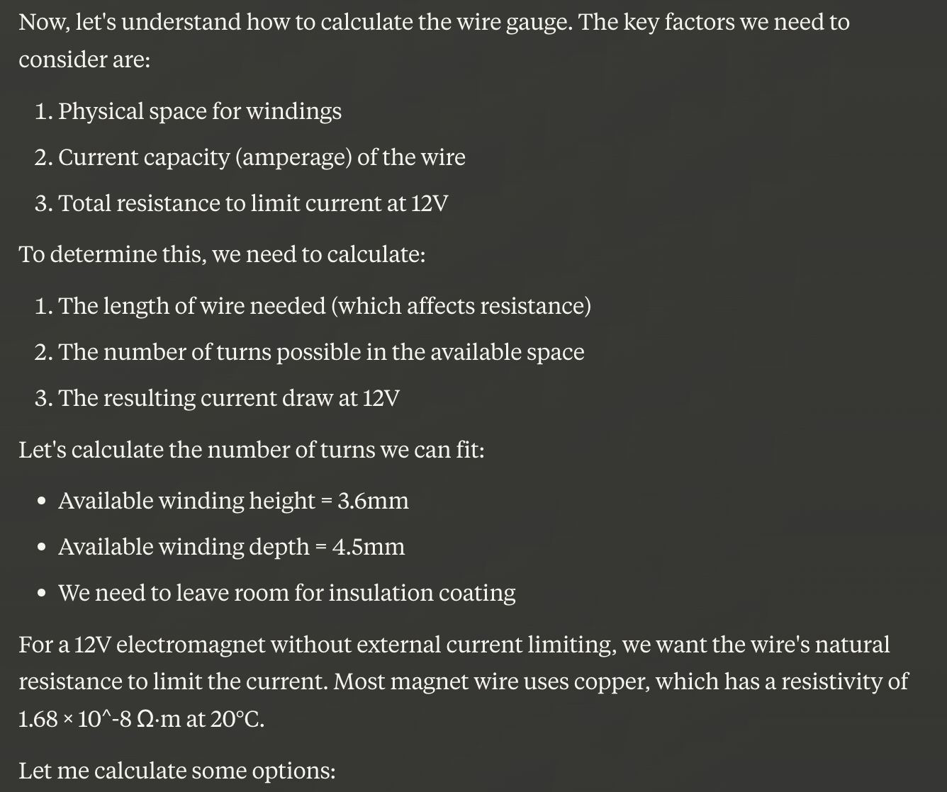
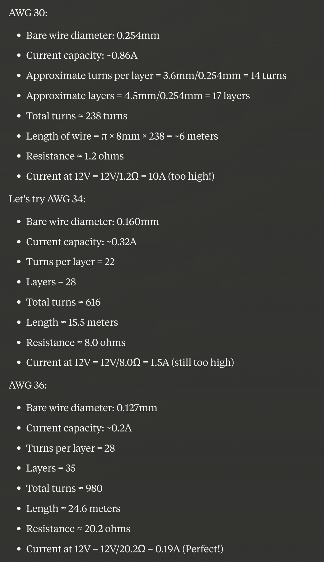
At this point, I turned to Claude. In the initial chat, it was clear that the coil should have a maximum diameter. Through that, we could determine the maximum length of wire at each gauge (yes, at this point, that detail seems obvious, but it hadn't occurred to me earlier). After I defined a maximum diameter of 17mm, it talked through the calculations and then went to work calculating a few options.
![]()
![]()
This was a great starting point and its explanation helped me understand how I'd do this myself next time. This form of teaching shows the answer first and how everything relates to it. This gives all the equations, units, and concepts more meaning.
The conversation continued as we explored how strong this magnet's force would be, what kind of force I could expect it to exert on a permanent magnet inside the coil, and what factors would affect this. At every stage, I can ask it to give more details, create charts, and truly help me understand how all these things work together. In a lot of ways, it's like an interactive textbook. When it makes a mistake, it's like a pop quiz, ensuring I'm still paying attention.
Summary
So far, Claude has taught me more in a couple of weeks of asking it questions at odd hours of the night than months of reading and trial and error. It has made me feel more confident in what I'm doing as I go from idea to early prototype.
I've even been using Claude for similar things in my day job. I've been a software engineer for the last ~20 years and am quite good at what I do. Even still, I have also been turning to AI to help me shape ideas or flush out new software systems.
It's a very powerful tool for your toolbox.
-
How it started
01/22/2025 at 06:00 • 0 commentsThis project came about at SuperCon (2024). While listening to presentations, my brain drifted off, thinking about actuators without gears and how to get away from the traditional loud noise of servo motors. I daydreamed about various gearless actuators that would be fun to play with.
For a hot minute I went down a rabbit hole looking at HAZEL actuators, which are really interesting. The research on them also provides instructions for how you can build them at home. However, the sticking point for me was that these actuators must be powered by well over 1,000 volts.
Ultimately, I landed on tubular linear motors, which you get if you unroll a stepper motor in a straight line. In the tubular variety, the magnets are placed in a tube that run inside electromagnetic coils.

The only problem was, I found limited step-by-step information on how to build one at home. Searching turned up a lot of videos of people showing off their motors (like this one), but no information about how they created them.
The Plan
I decided to start my journey using this research as my guide. In this configuration, the magnets are positioned inside the tube with like-poles facing each other. This helps to concentrate their magnetic fields and, in theory, improves the motor's power output.
![]()
I've never built a motor before, or created a stepper motor driver from scratch. I understand the basic principles, but I know there are a lot of fine details that make them work and run smoothly. In short, I've got a lot to learn.