Peter Wallhead
-
Installing the ROS 2 teleop package
07/27/2025 at 01:39 • 0 commentsI had to build this package from source because it was no longer available on the ROS 2 package server for Humble.
cd ~/ros2_ws/src
git clone https://github.com/ros2/teleop_twist_keyboard.git
cd ~/ros2_ws
rosdep install --from-paths src --ignore-src -r -y
colcon build --packages-select teleop_twist_keyboard
source install/setup.bash
ros2 run teleop_twist_keyboard teleop_twist_keyboard
I then modified the node script (~/ros2_ws/src/teleop_twist_keyboard/teleop_twist_keyboard.py) to set the default speeds on lines 156 (speed) and 157 (turn) instead of adjusting them using the keyboard on every run, before rebuilding.
-
Adding Dynamic Course Correction - Update 1
07/25/2025 at 02:54 • 0 commentsThe first step to get the robot driving forward in a straight line was to finally get it driving wirelessly under its own power.
The Pi 4 is super power hungry, especially at boot with the RPLidar connected, and requires a power bank with a decent 3A output. The motors are currently running on only 6V, supplied by a pack of AA cells, but have been tested up to 12V in short bursts.
The cheap gearboxes I'm using have a 48:1 gear ratio and don't provide enough torque at lower voltages on carpet, but run well enough on hard surfaces.
The initial method I tested for course correction as the robot drives forward was to compare the difference between the raw encoder ticks from each motor and then to slow down or speed up the corresponding motor to correct for the difference.
In this first test the robot's wheels were off the ground and allowed to spin freely. Initially, this method looked promising until it began oscillating left and right as it overshot the target point and then over corrected.
The RVIZ2 plot below shows the pose estimate for this test.
I ran some additional tests using this same method with the robot driving on a hard surface, and the results were similar; a hard twist to the right and then a series of wild oscillations.
Further testing revealed that my encoder ticks publisher was running too slowly, at only 5 Hz, and this was contributing to the wild oscillation I was seeing. I have since increased this publisher speed to 50Hz.
I then updated the method I was using to recalculate the motor speed error to a partial PID loop, only setting the Proportional gain.
In the RVIZ2 plot over 100m with the wheels freewheeling, it’s clear that this new method was going to be a lot more successful. While there was still a slight twist to the right as the motors came up to speed, the robot’s path remained relatively straight.
In the final test performed for this update, I ran the robot on the ground with the proportional gain set 3.1 (which was the gain that gave the best performance in the freewheeling tests). The RVIZ2 plot below shows the now familiar twist to the right, and then a straightening as the error slowly decreased over the 4 to 5m long run.
-
Encoder Node V1 - Onboard Testing
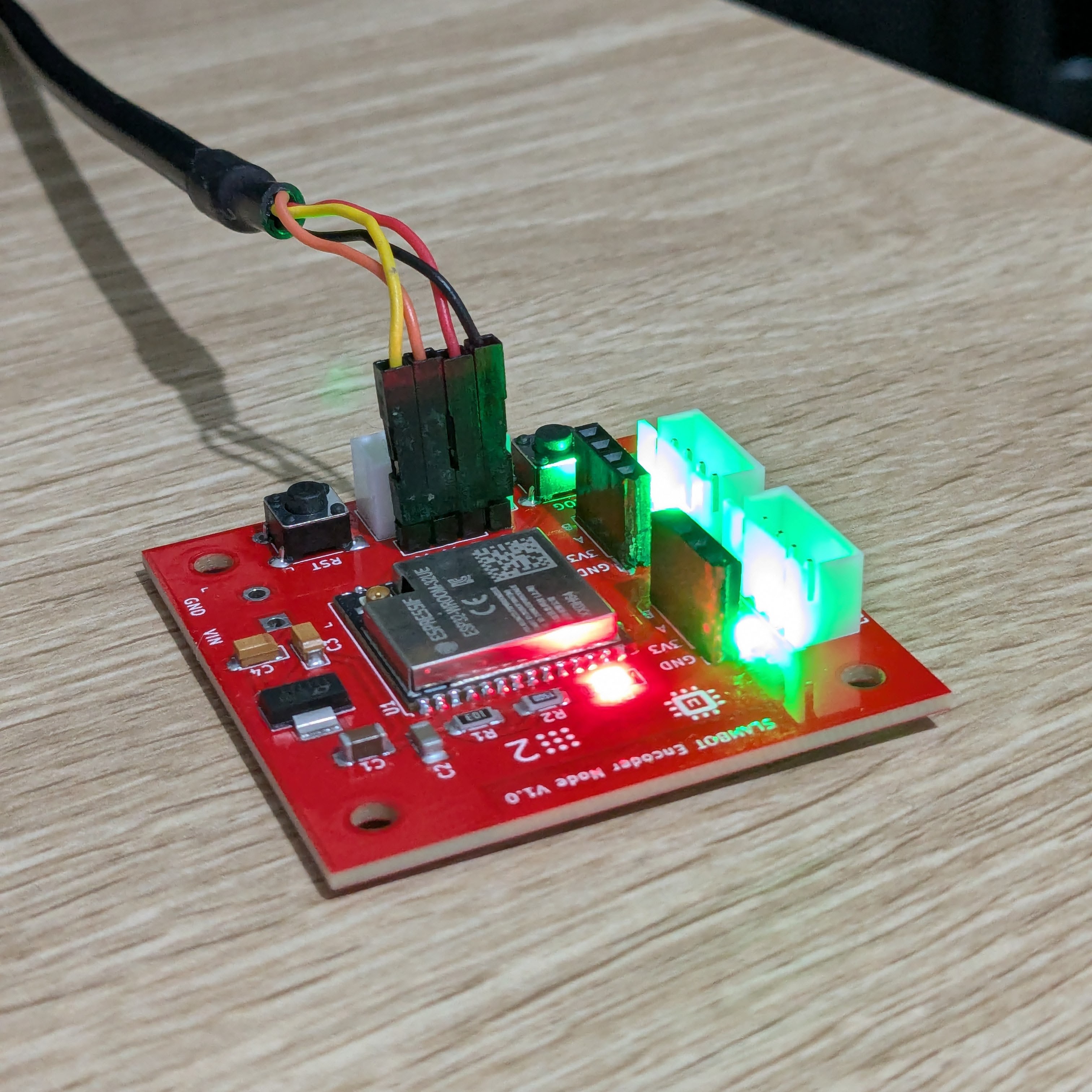
06/08/2025 at 04:14 • 0 commentsWith the Encoder Node PCB finally mounted onto the robot, testing its functionality can begin.
Here I'm demonstrating that the board is reading ticks from the encoders and publishing them correctly using the custom encoder_ticks interface. The green LED indicators are flashing every time an encoder tick count changes for that wheel.
While the onboard Raspberry Pi 4 is currently hardwired, the plan is to power it from a rechargeable battery through a voltage regulator, and connect it to my local wifi network.
-
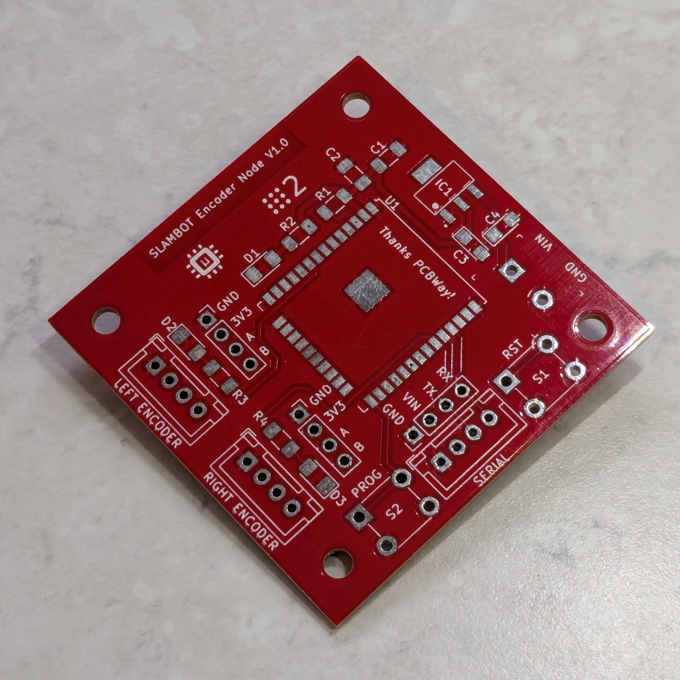
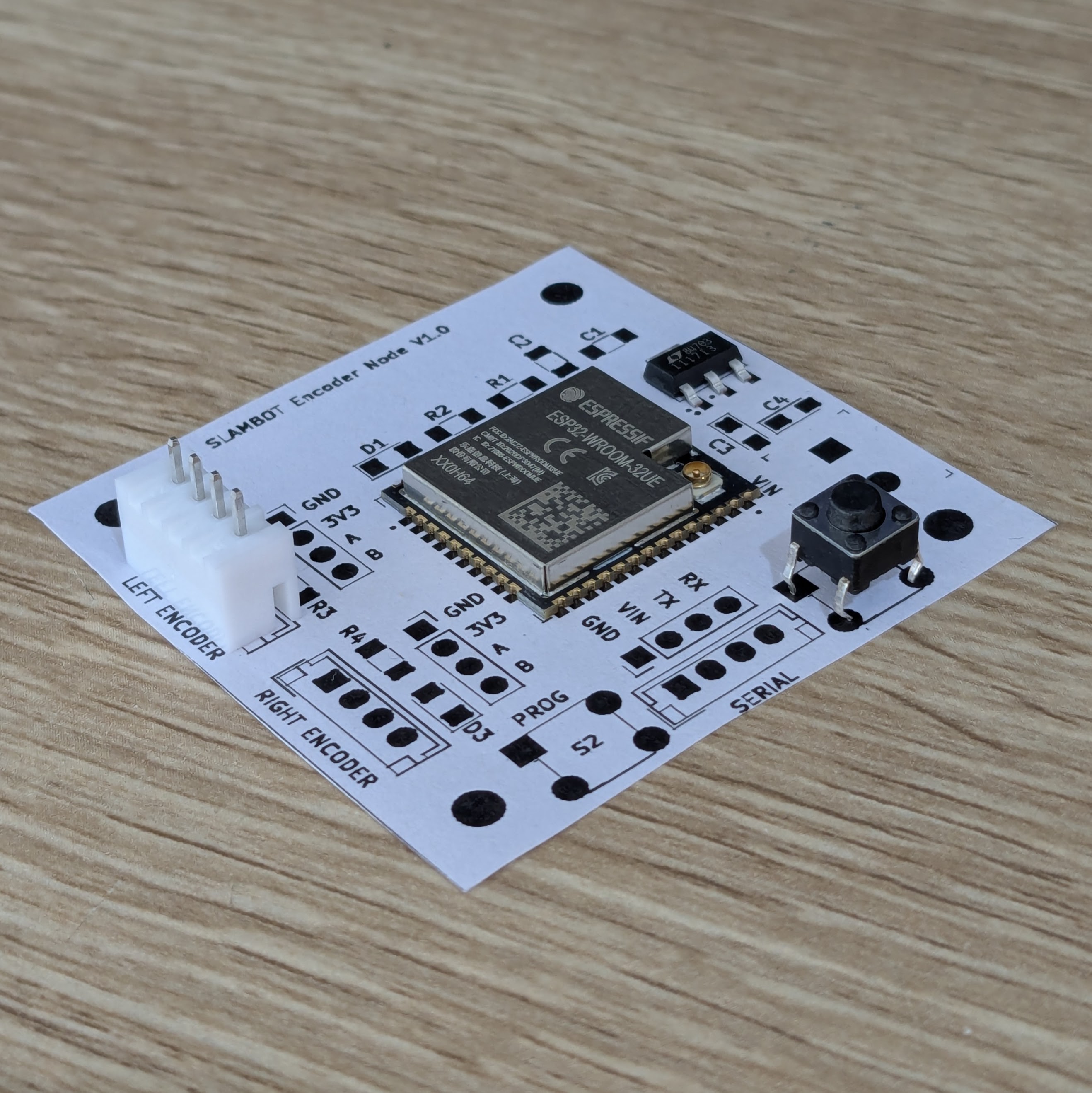
Encoder Node PCB V1 - Assembled Board
05/26/2025 at 11:43 • 0 commentsThe Encoder Node V1.0 PCBs arrived during the week and I quickly assembled one to start bench testing. Thankfully all the JST sockets fitted after my previous modifications, and it booted perfectly the first time.
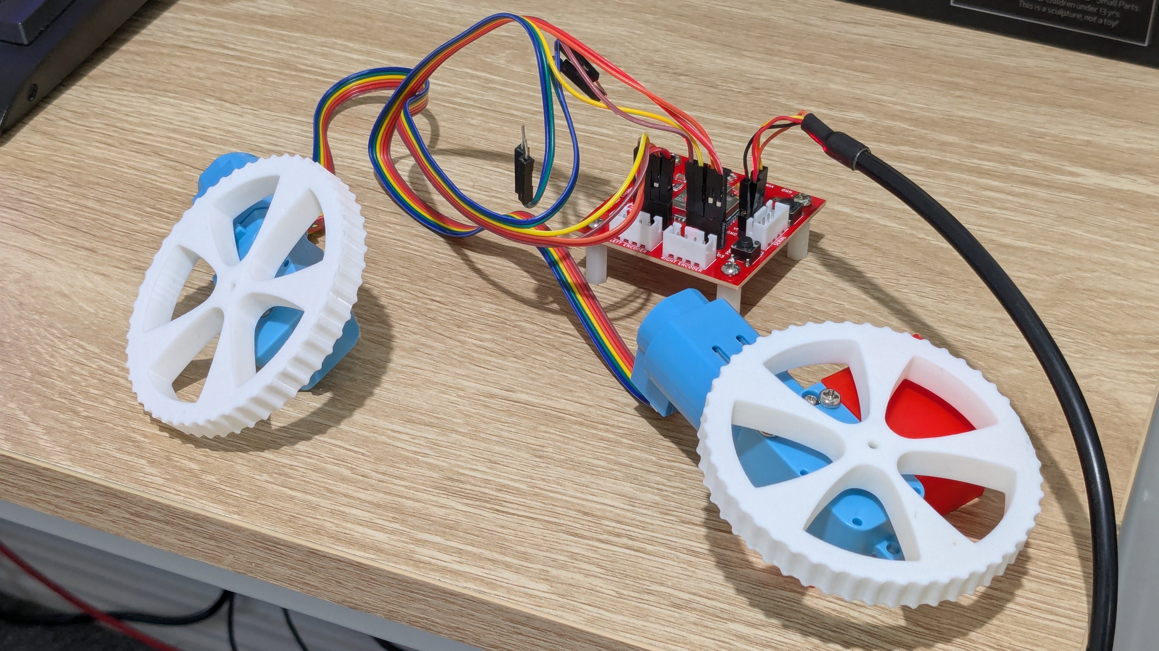
This board is a critical component for determining the robot's current position within its environment.
The next step will be to mount one of these boards onto the robot itself (the SLAMBOT) to collect real-world data to incorporate into the rest of the ROS 2 infrastructure I've built out during the last month.
![]()
![]()
![]()
I was very grateful when PCBWay reached out to me to sponsor a PCB for this project as it made it so much faster to go from bench prototyping to an assembled PCB. Thanks PCBWay!
-
Encoder Node PCB V1 - Bench Prototyping
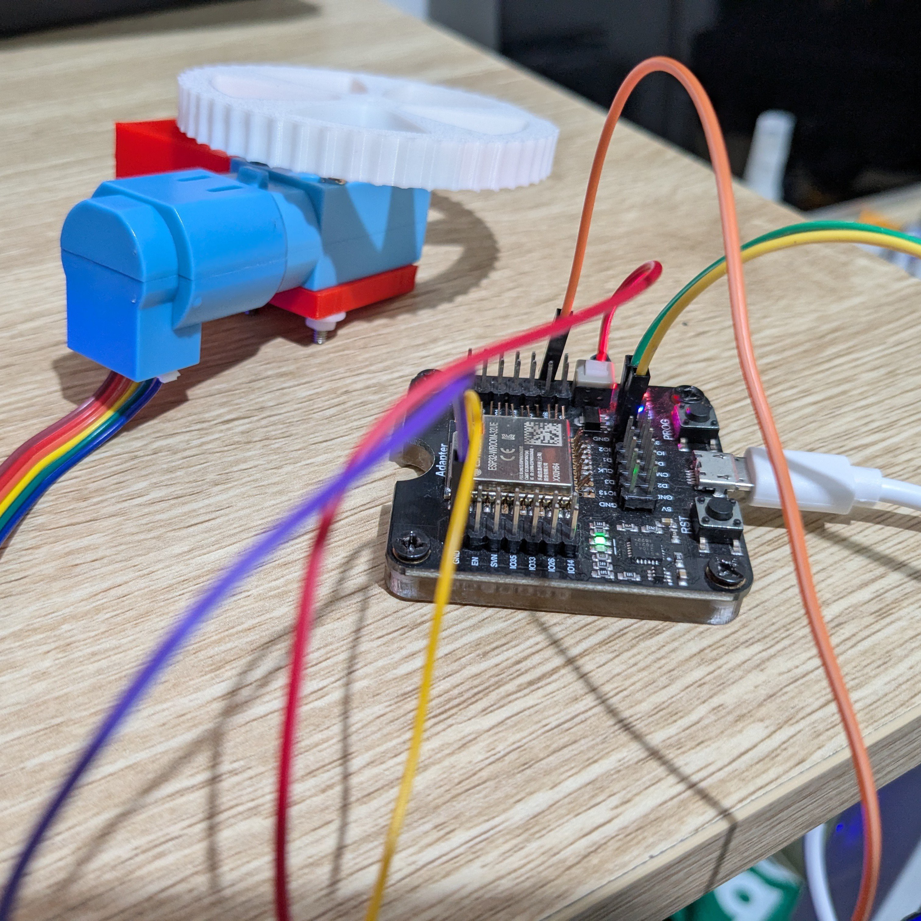
05/17/2025 at 02:44 • 0 commentsWhile designing the schematic for this PCB I dug out an old ESP32 programming dev board to ensure that each GPIO I had selected could be used as required.
![]()
I found a couple of GPIOs that either had dedicated functions for this dev board or needed to be in a particular pull-up or pull-down state at boot so these couldn't be used for other purposes.
Prototyping in this way also helped me to validate the Encoder Publisher code that will run on the ESP32-WROOM-32.
The PCB is currently on its way from a new sponsor of this project, PCBWay!
-
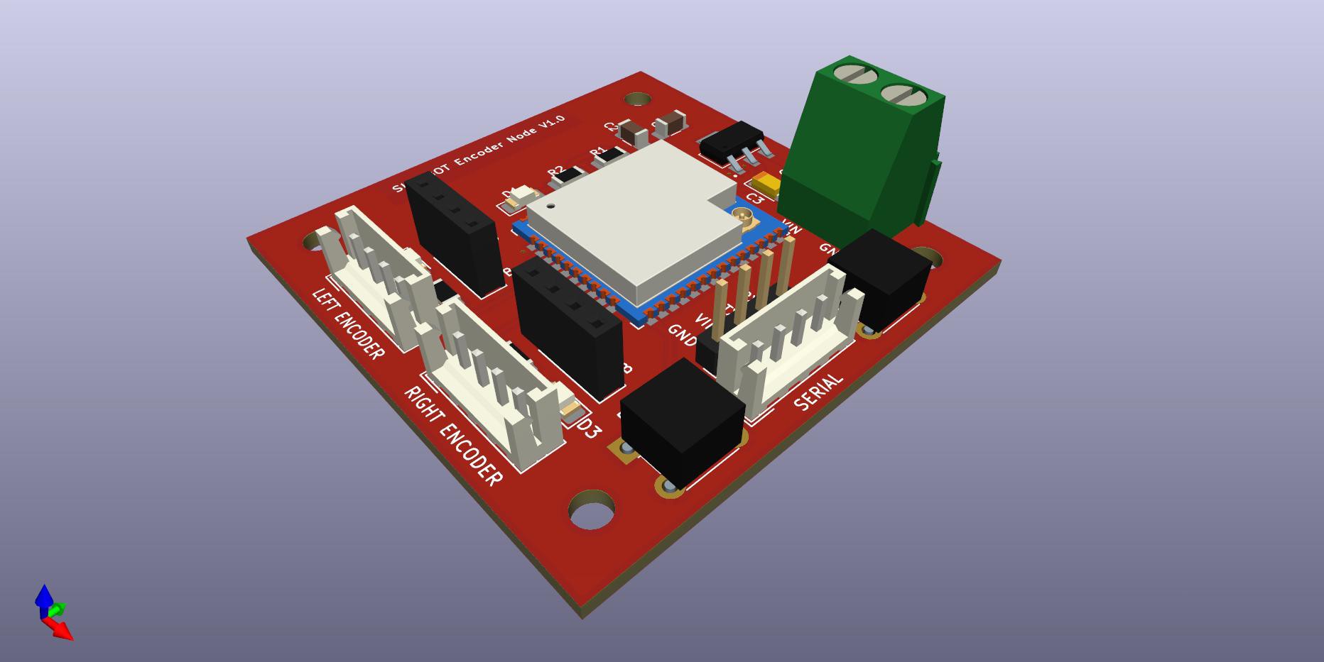
Encoder Node PCB V1 - Component Fitment
05/09/2025 at 05:01 • 0 commentsDesigning a dedicated board to count encoder ticks and publish them using micro-ROS.
This board is only 50mm by 50mm, and the 4 corner mounting holes will align with the hole pattern in the platform level plates.
![]()
Using Paper Aided Design (PAD) to validate the component footprints and discover any accidental intersections.
The JST connector footprint I selected is too small, so I'll need to swap these out and move some other components around to fit them.
![]()
-
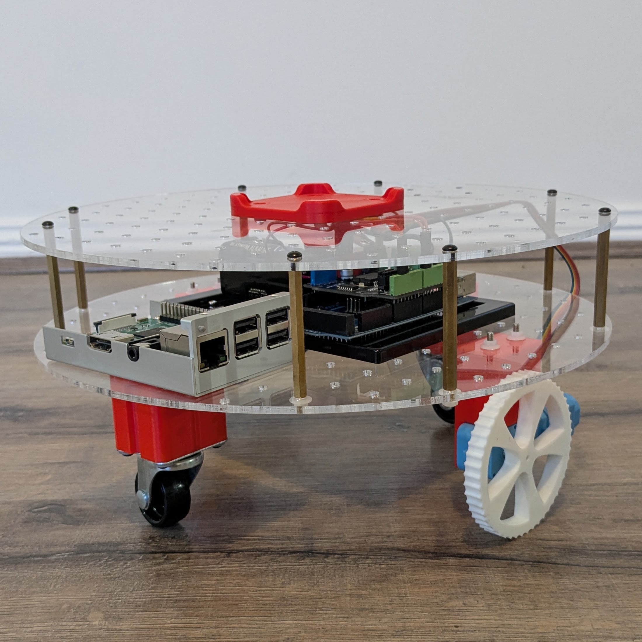
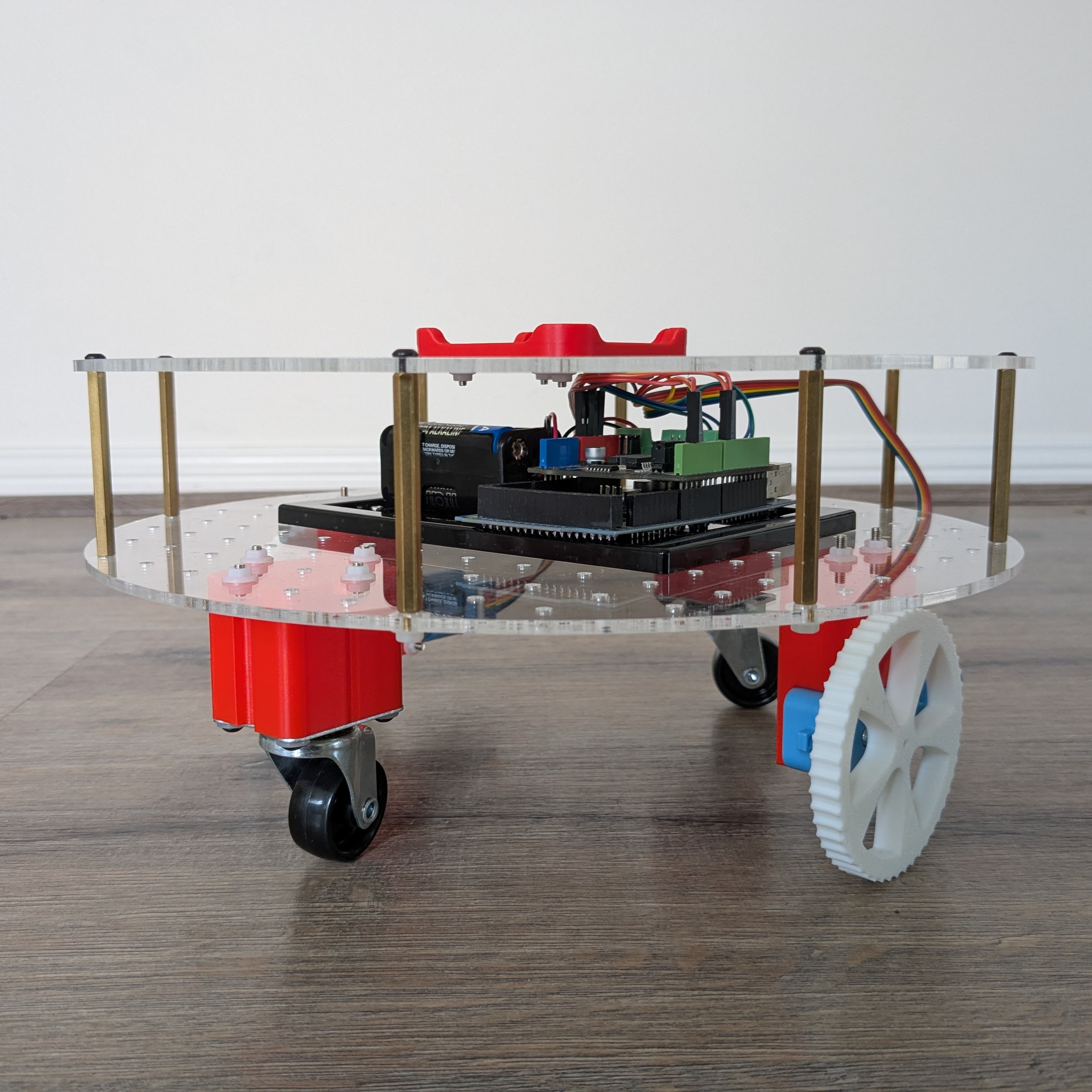
Hardware Test Fitting Begins
04/20/2025 at 07:19 • 0 commentsTesting different component layouts with an Arduino Mega as the motor driver and a Raspberry Pi 3 Model B for a controller.
The RPLidar unit will likely sit in the centre of the upper level to provide the clearest view of the robot's surroundings.
![]()
![]()
Indoor Autonomous Mobile Platform
Building a prototype Autonomous Mobile Robot (AMR) to apply ROS 2 and SLAM concepts in a real-world environment.