 Sebastián Elgueta
Defining the process
To being able to flexibly fabricate the intended structures, the following process was devised:
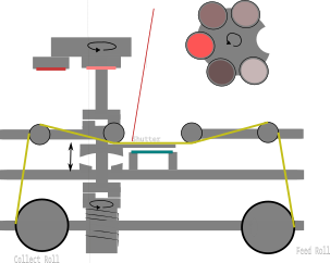
One starts with a bare substrate, covered by the unmarked mask 'web'
and a shutter between them. The target carousel is placed in such a way
that it lets laser light pass through it. Either under vacuum or an
unreactive gas, the apertures are defined.
When the apertures are cut, the shutter is removed and the proper atmosphere is set onto the chamber. Then the proper deposition process is performed (either from a single target or a given combination).
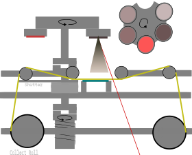
Once the deposition step is completed, the mask web is moved until only unmarked tape covers the substrate. This sequence may be repeated until the mask is completely consumed.
Evidently the shutter is required to protect the substrate from debris and laser ablation. It quite a compromise, as the distance between shadow mask and substrate heavily influences the achievable resolution.
As a solution, the mechanism is designed in such a way that whenever the shutter moves into place, it pushes the substrate stage onto a lower position. When the substrate is uncovered, the substrate stage reciprocates back, with it's position determined by a simplified kinematic coupling.
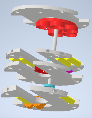
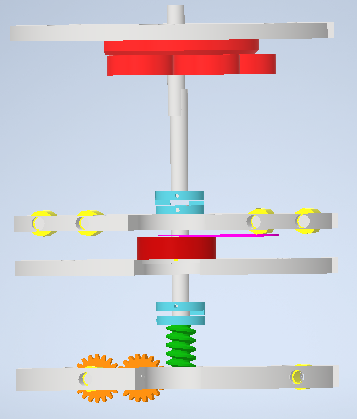
Now such mechanism seems to have a fair bit of degrees of freedom: Target carousel, shutter, and mask roll movement is required. However, they move in a fairly well defined sequence, so in principle all movements could be partially coupled to one another in order to reduce the required actuation elements.
A First Iteration
The Prototype
While 3D printed components are usually not vacuum compatible (at least not as is), they were a great tool to test the ideas involved, and gradually start implementing the final pieces. Here are a couple of pictures of the process:
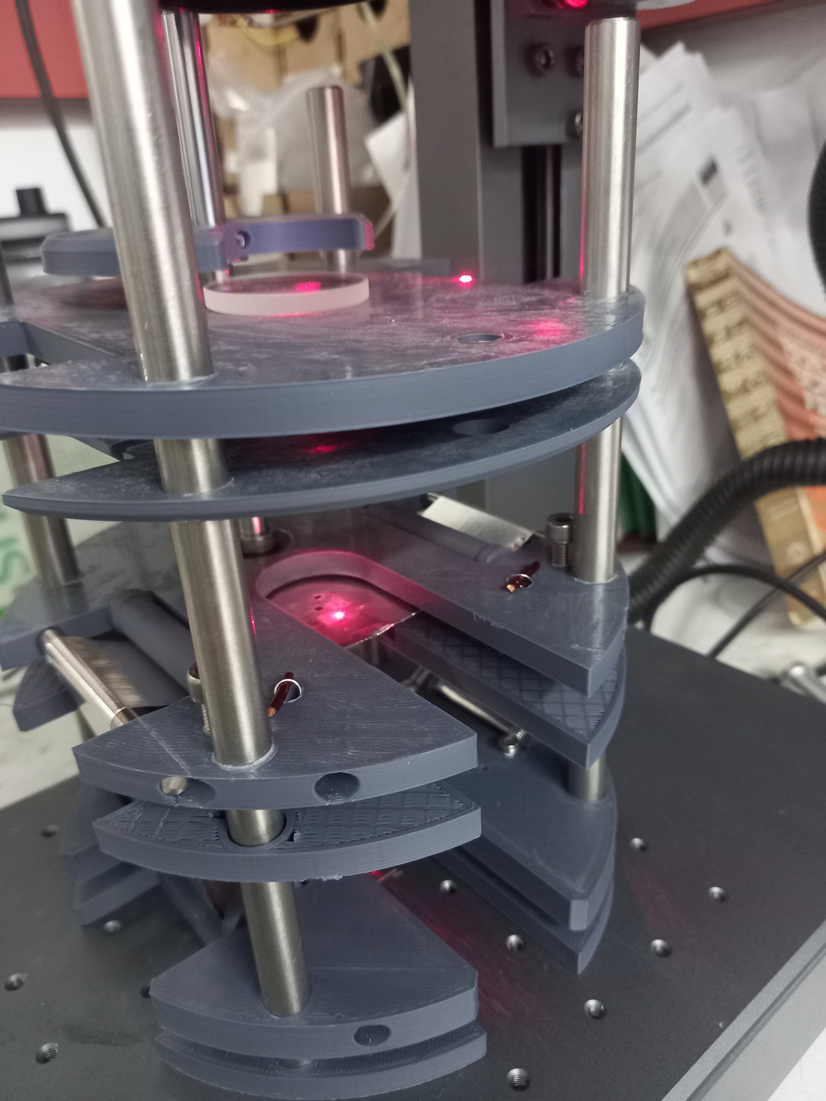
It was crucial to test the resistance of the tape after marking.
Actual Mechanism Fabrication
As the mechanism is mostly composed of planar 'plates' with different apertures, it's well suited for processing with laser cutters or waterjets. However, I wasn't very confident on my designs, so I rather chose to fabricate the whole assembly out of duraluminum stock.
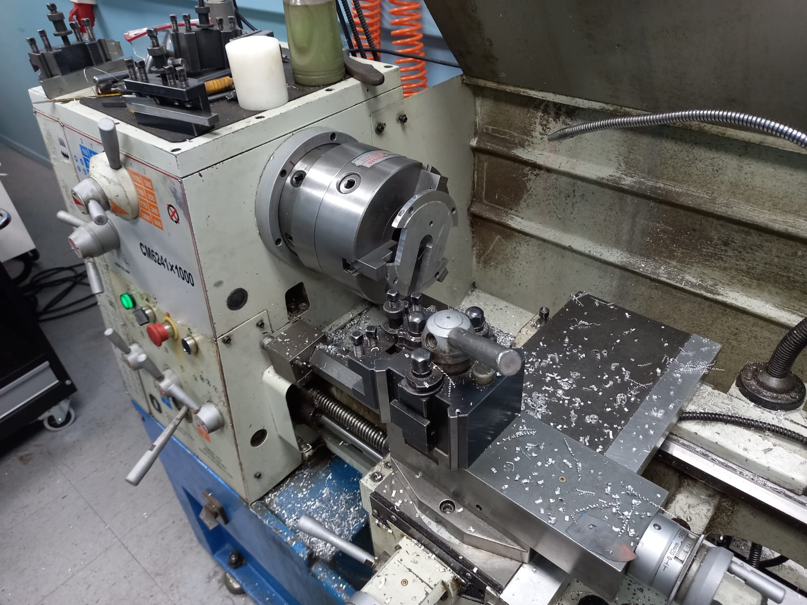
I started from a 6' cylinder , and turned it on the lathe to the appropriate (149 mm) diameter.
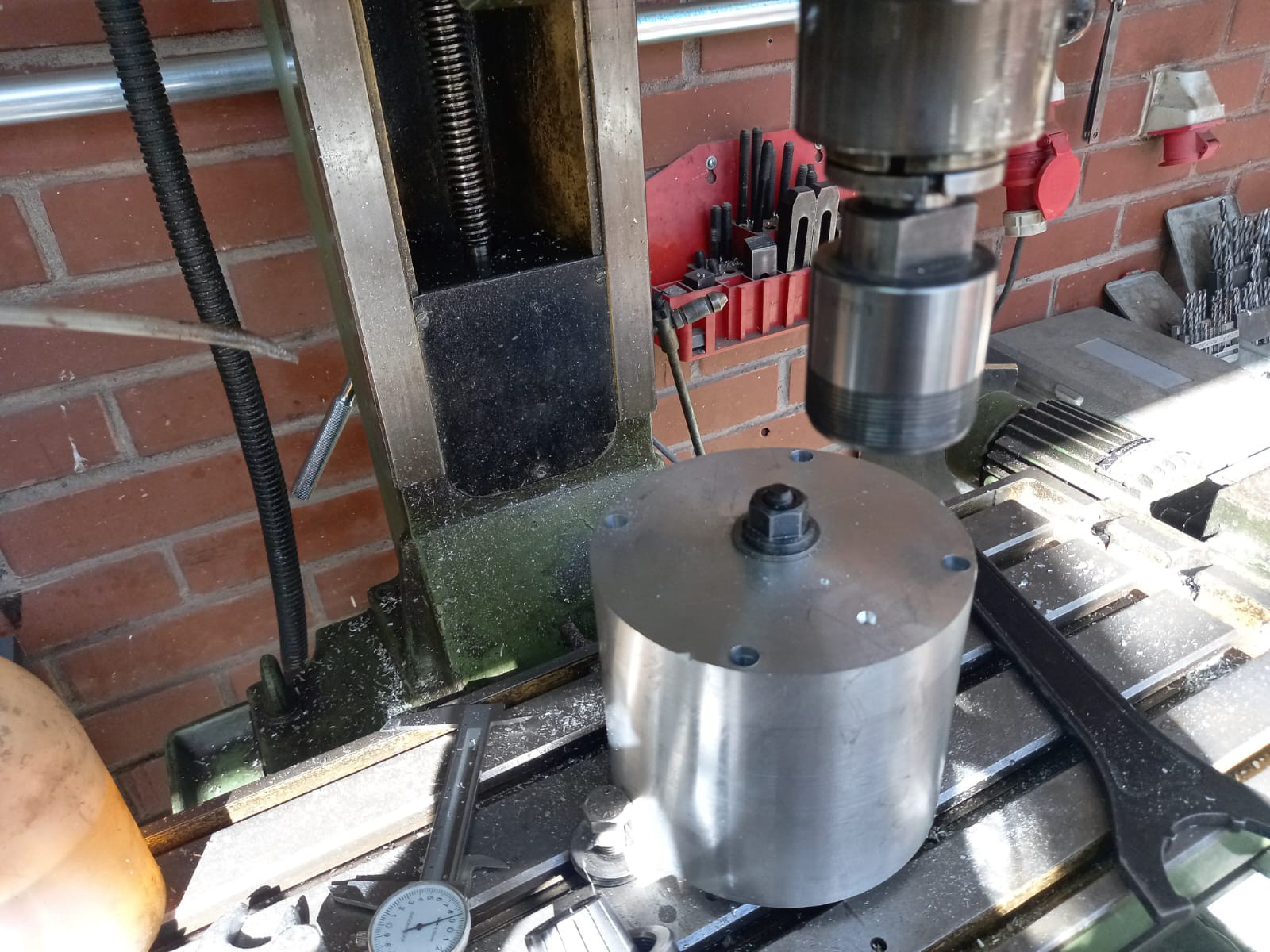
After that, all the common perforations were made in a (relatively unsuccessful) attempt to keep al the plates and moving axis aligned. The common features between plates were machined as well:
After that, each plate was cut from the main block (a royal PITA)
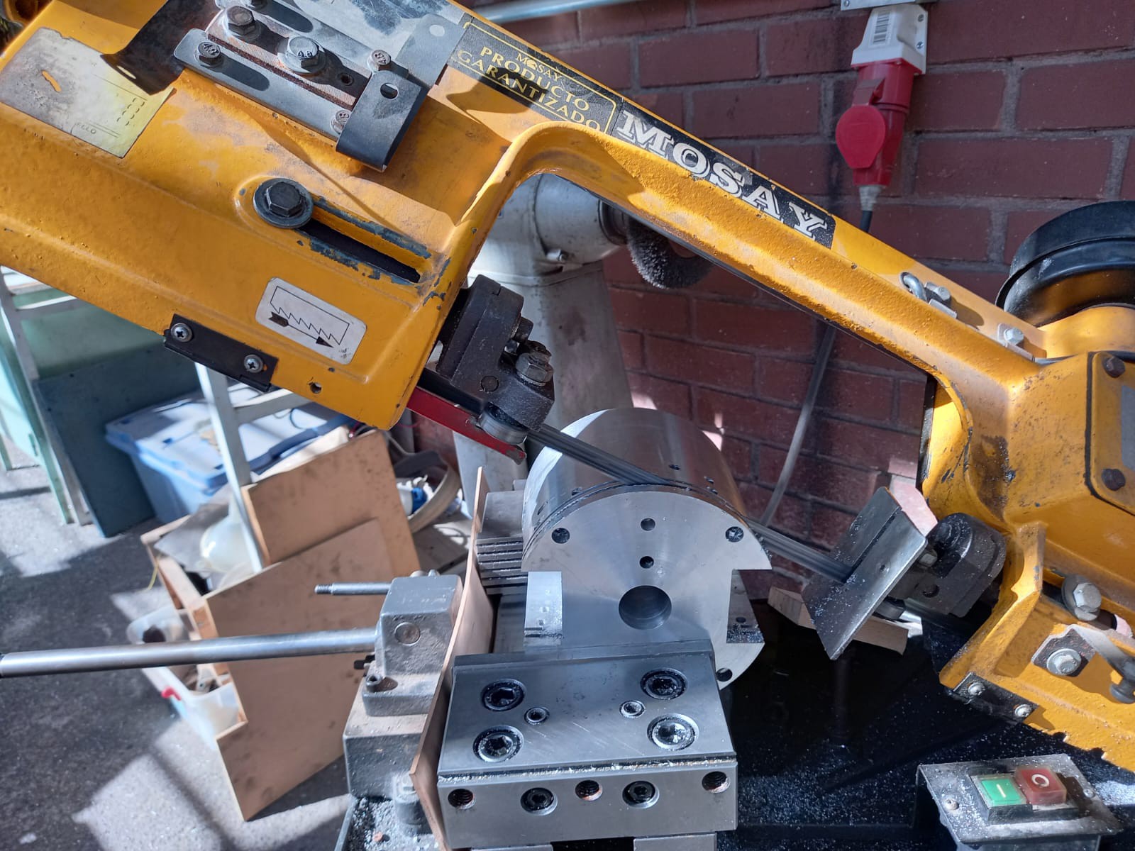
And finished on the lathe:
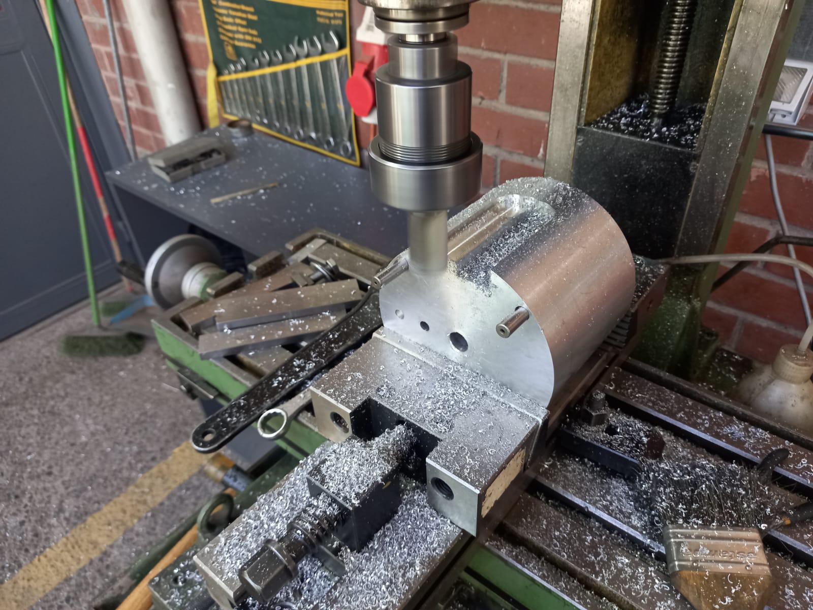
Or given some extra details in the mill:
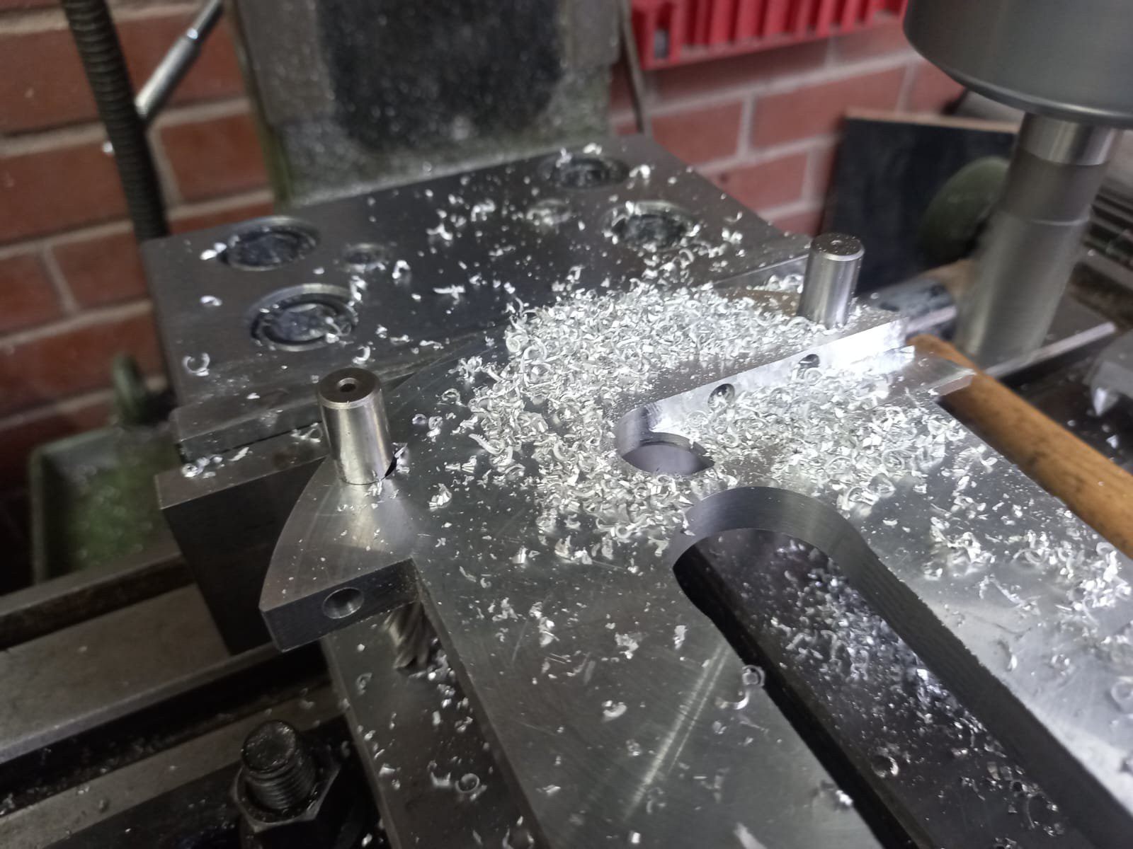
The process was repeated several times until the mechanism was completed:
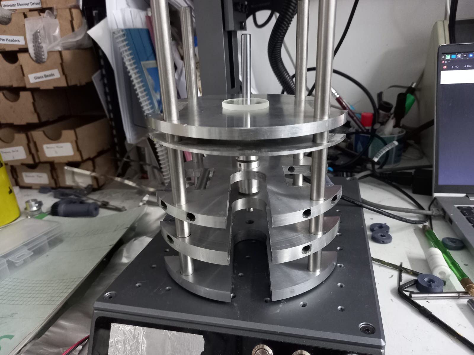
The remaining components (rollers, target carousel, couplings) were machined with standard techniques (and in those cases it actually made sense to do so).
Evidently the manufacture could be simplified a lot using the proper tools to fabricate the plates, so I'm currently working on designing a mostly laser-cut version.
Discussions
Become a Hackaday.io Member
Create an account to leave a comment. Already have an account? Log In.