 Sebastián Elgueta
Device Fabrication
As outlined in a previous log, the design process mainly involves material selection, layout design and prepping the files for the laser cutter control software. Now it's time to see how the machine is used.
Preparing the Mechanism
Anyone who has worked with vacuum chambers knows that is usually not a breeze. While they are usually designed for modification by being quite modular, in the sense that the flanges allow changing the overall configuration flexibly and access to the different components, it still isn't a process that is trivially easy nor practical.
Therefore, ease of use was one of my primary design considerations, the idea being that changing material targets and substrates would be a quite frequent process while using the machine as a material science research tool. In the standard configuration of PLD chambers, the target manipulator is usually fixed in a flange and therefore any changes are done inside the chamber, at least in my experience.
For my design I opted for a 'capsule' arrangement, where most of the moving parts could be removed from the chamber, allowing easier 'servicing'. This design dates back to the first iteration.
The capsule itself is quite modular, consisting mainly on planar plates held together by rods, and arrangement which allowed to tune the different critical distances between the different components.
Most of the components are fastened with M3 headless screws. So, first we fix the targets:
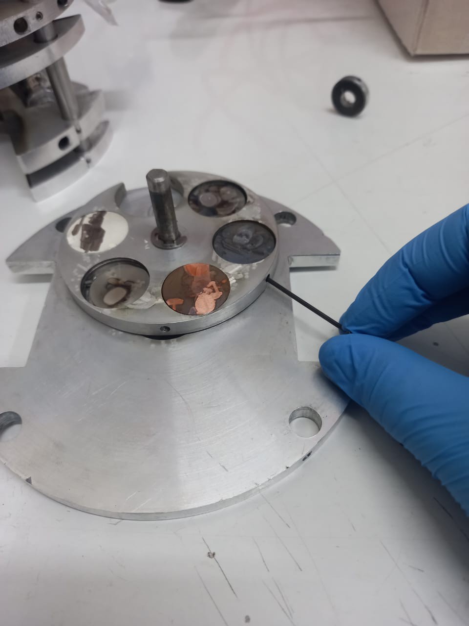
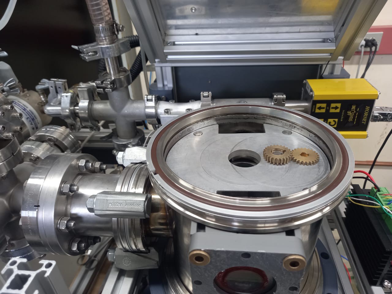
And then proceed to add the protection plate (which is mainly to avoid the contamination of the targets with aluminum from the tape machining process) and mount the top plate, along with the gears used to transmit the motion from the actuator to the main axis of the mechanism.
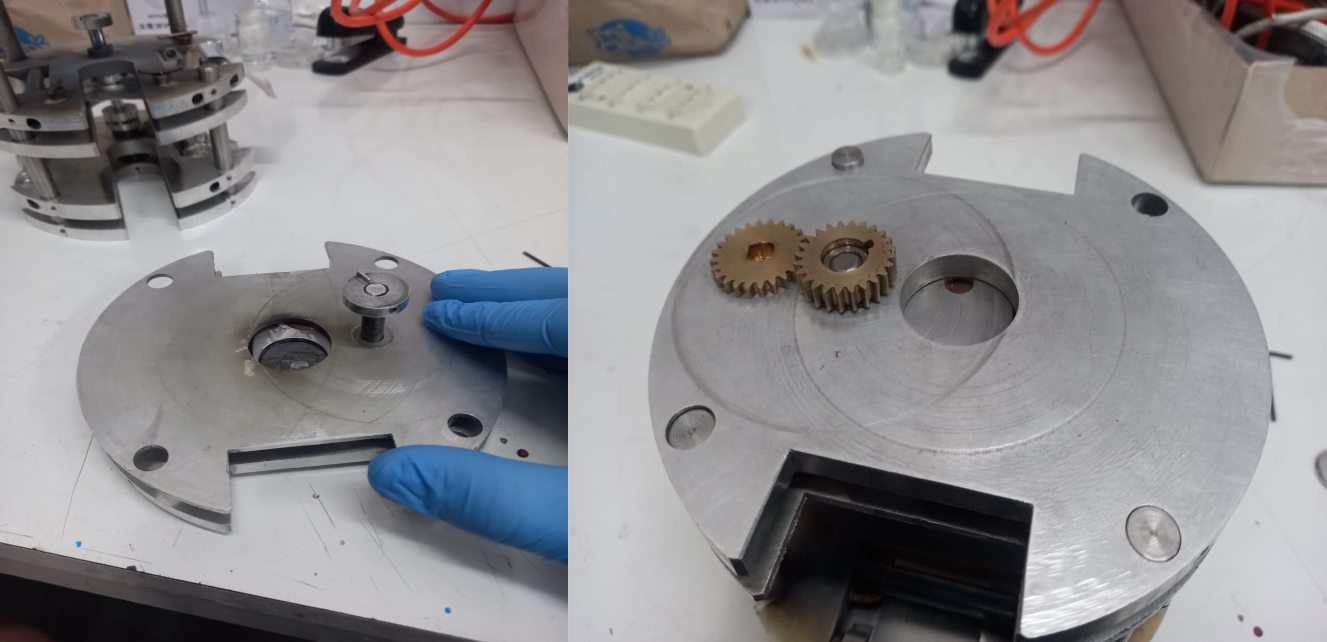
The gears are required to provide clearance between the actuator and the laser head. Notice the notch on the left gear, which is used to quickly couple the actuator with the mechanism.
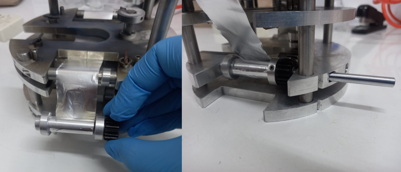
Next one has to place the tape. Currently I'm using 35 micron aluminum foil, which is cut to a width of 35 mm and a length of about 1.5 meters. That in principle allows about 50 different mask, which in practice means that one has to change the tape after 10 deposition processes.
The mask is fixed to the moving roller with aluminum tape (I know, not ideal), which is then properly placed by means of it's removable axle.
Afterwards, I usually mount the substrate. I'm using glass disks of about 25mm of diameter and 1mm thick, sold as watch covers. They are cleaned with both IP alcohol, Acetone and DI water and mounted onto the substrate holder.
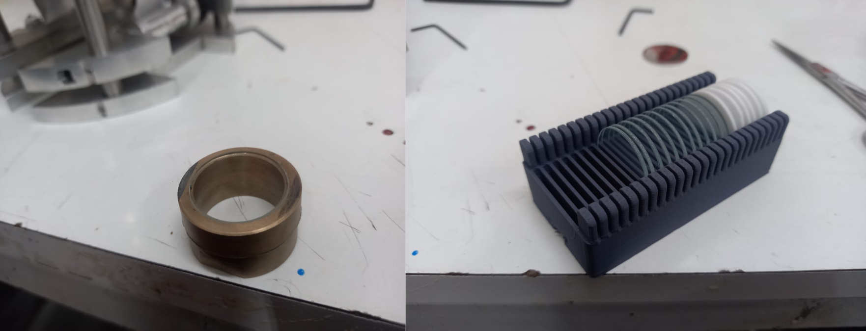
The holder has a couple of notches which mates to the 'substrate plate', allowing the placement of the substrate under the mask tape without to much complications.
Now it's time to discuss an important issue with the technique: The relation between repeatability and resolution.
A conundrum: Mask-substrate distance and the shutter
In case you recall, perhaps the main characteristic of the system is that the masks are machined in place, which in principle allows the whole system to 'inherit' the feature placement repeatability from the lithography tool, namely the galvo laser engraver. Now the problem here is that laser micromachining is both a dirty ( as in producing particles that may contaminate the substrate) and an aggressive (in the sense that is quite easy to damage any surface placed closely to the mask ) process. The only solution I could came up that at least partially solves this two issues is to place a shutter between the mask and the substrate during the machining process.
The shutter is basically a thin plate made of sheet steel which is coupled to the main axis of the mechanism in such a way that it covers the substrate when the aperture of the carousel is in place.
While very effective to protect the substrate from laser damage and partially effective to avoid particle contamination, the issue with the shutter is that it requires a rather big clearance between mask and substrate, which negatively affects resolution.
To see why it's so, let us think about how the matter flows from target to substrate. The ablation process takes place in a rather small area, which may be considered punctual for our discussion. The ablated material expands from that point with a certain angular divergence, and also some expansion due to diffusion,
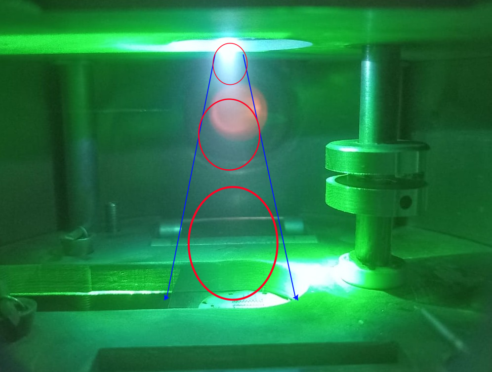
As this material passes through the mask apertures, it' keeps it's angular divergence (and perhaps that divergence is subjected to certain variations at the edges of the apertures ), generating a 'shadow ' that is both larger (and perhaps displaced) from the aperture shape:
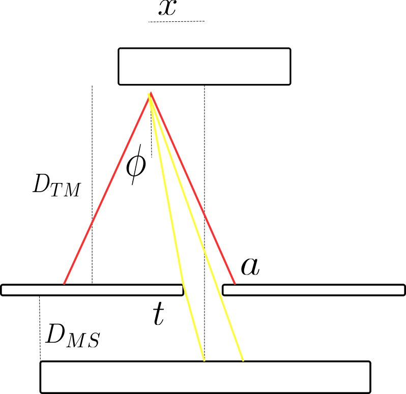
This geometrical 'blurring' is proportional to the angular divergence of the plume and the distance between the target and the substrate, being the latter the only thing that we can (easily) control.
While the actual situation is slightly more complicated (in practice a deposition process will take place from multiple points over the target, and therefore the final deposit will be the sum over such points, and there are also considerations regarding gas phase diffusion and 'unconstrained' movement of the particles over the substrate ), it still quite clear that the solution in to minimize the mask-substrate distance as much as possible.
A partial solution: The reciprocating substrate stage
To overcome such resolution issues, I chose to move the substrate stage while the target is placed over it. While it may seem that this defeats the purpose of keeping the substrate static with respect to the laser head, I intended to take advantage of the mechanical repeatability of a kinematic coupling to solve that issue, The idea is that the substrate stage position is with respect to the mask stage determined by 3 sphere-ended screws :
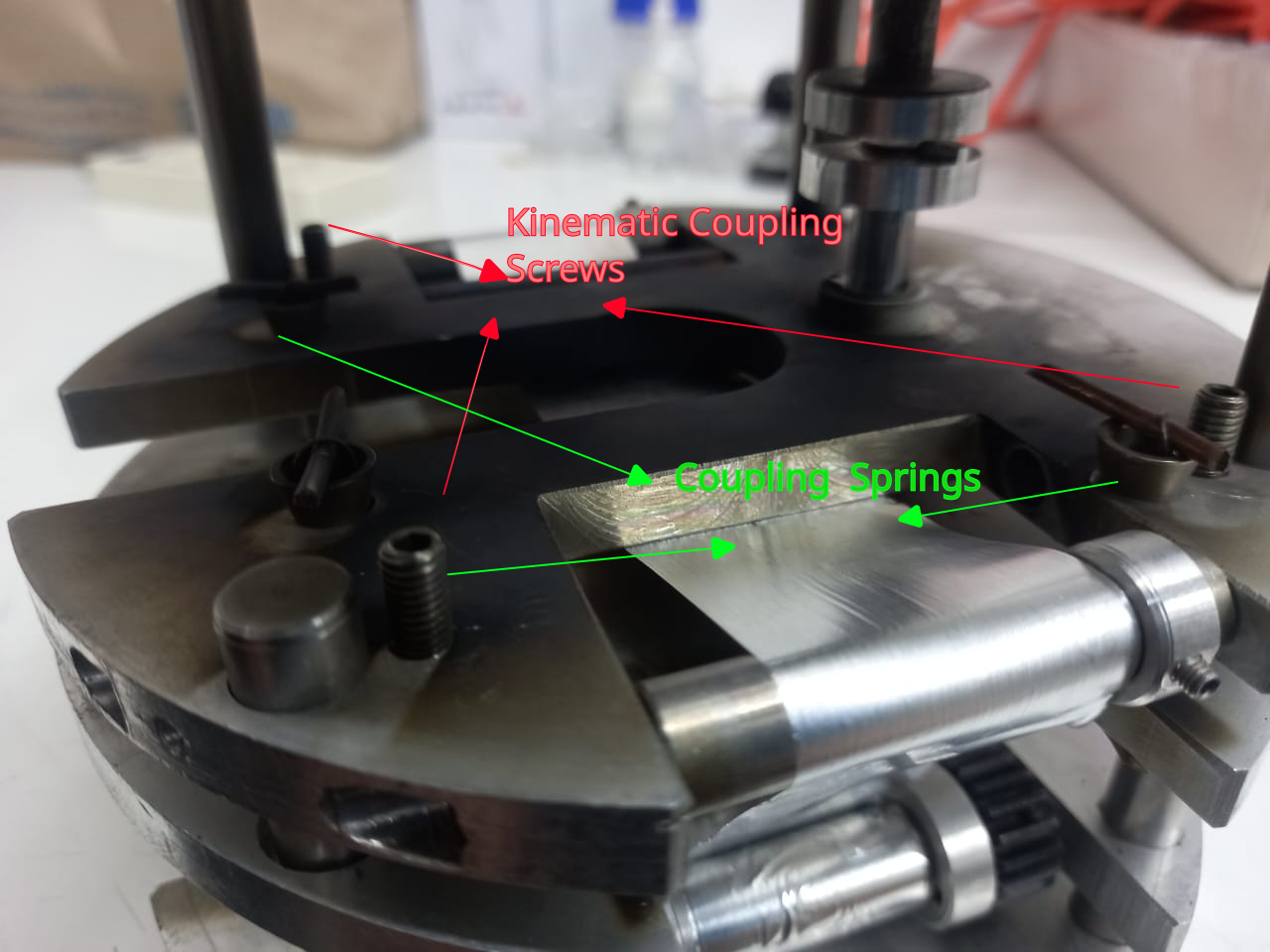
Such screws allow the tuning of the plane of the substrate and the mask (something quite analog to bed leveling in a 3D printer) and the distance between those planes.
So basically what happens is that when the shutter is moved into place, it 'pushes' the substrate stage downwards a couple of millimeters. Then the mask machining takes place, and when the shutter is moved the substrate stage moves back to it`s original position, which theoretically is repeatable to within the surface roughness of the mating surfaces.
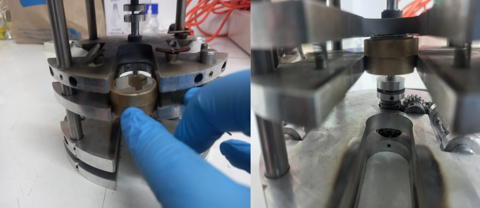
Here's a view of the process:
Along with a bit more clear view from the side. Notice the tape displacement and the partial coupler between the main axis and the worm gear.
The mechanism is still not perfect, as the stage movement is more of a tilt than a proper displacement, and the repeatability of the substrate placement could be improved considerably by using a true kinematic coupling (as the screws currently mate with some holes rather than proper constraining surfaces). Also the shutter has to be cleaned and covered with copper tape periodically due to the amount of damage associated with mask machining. Sometimes the tape is welded to the shutter, which leads to complete failure of the ongoing set of depositions.
Chamber conditioning
After getting that out of the way, we shall continue describing the fabrication process. Now it's time to get the 'capsule' onto the chamber.
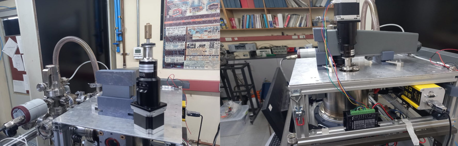
The whole system in mounted on a wheeled rack, and placed close by to the laser source. The laser is from another experiment, but the owners kindly let me use it by placing a removable mirror in the beamline.
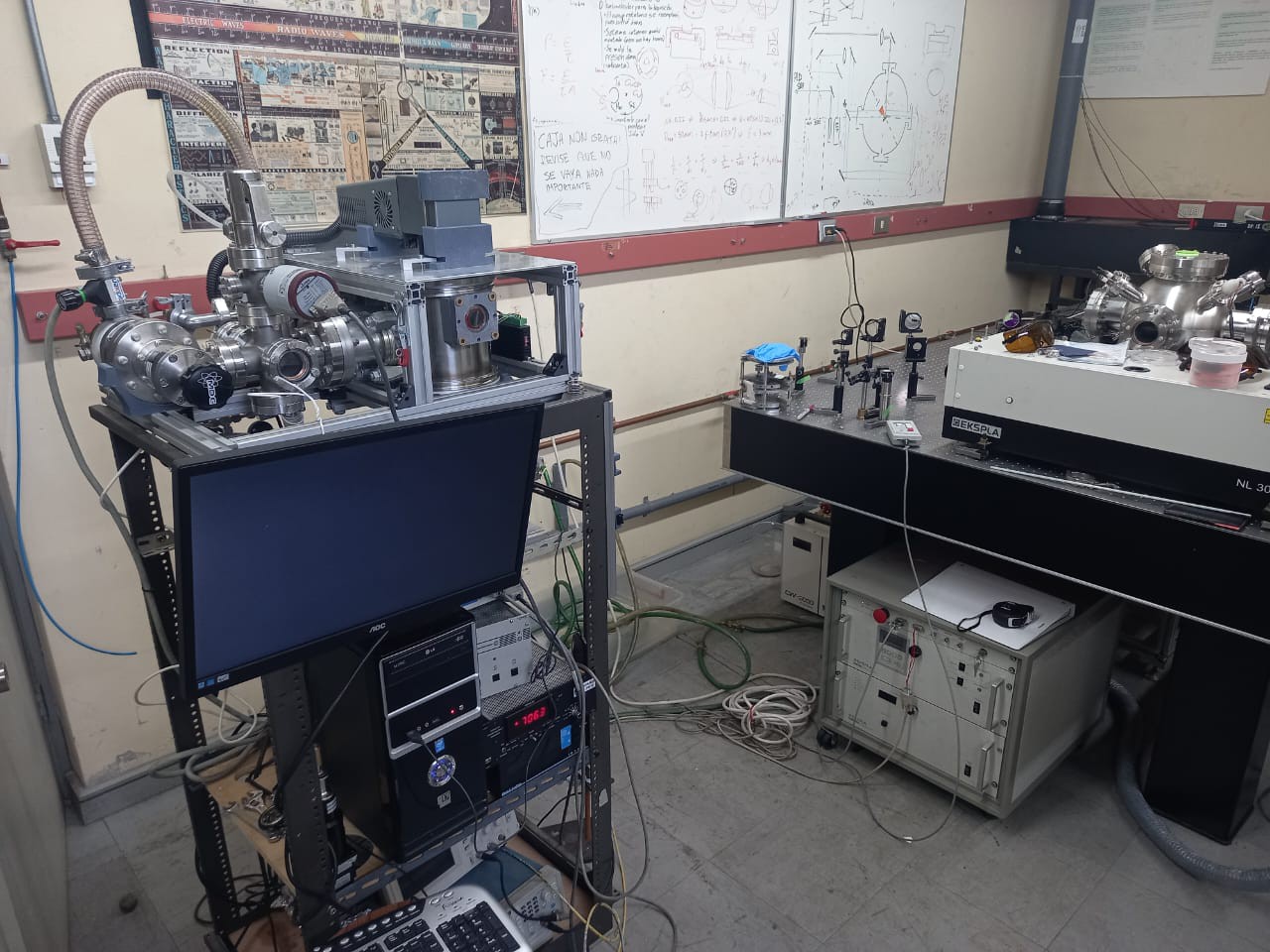
The laser is mounted onto a hinged table, which can be lifted to place the capsule in the chamber:
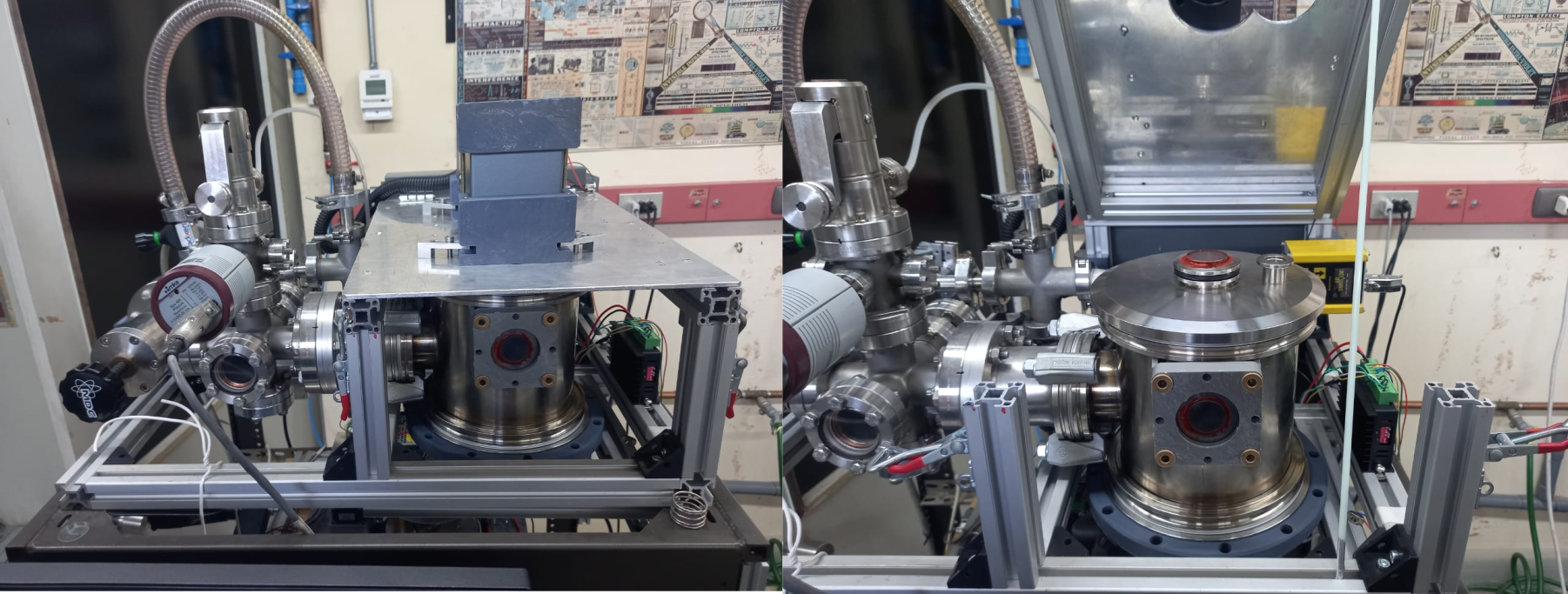
Then the top cover is removed and the mechanism is placed inside the chamber, taking care of placing it in the correct orientation.
Afterwards, the cover is placed again and the table secured with some clamps. Then the actuator (basically a rotary feedthrough with a custom coupler which fits the notch in the outermost gear) is inserted on the cover flange (kf16) and bolted using a light vacuum clamp.
Now everything is ready to start the actual deposition process. This writeup is getting a bit too long, so I'll leave the detailed description of it for the part III of this log.
Discussions
Become a Hackaday.io Member
Create an account to leave a comment. Already have an account? Log In.