Jeremy
-
It [the simulation] walks!
11/27/2025 at 03:29 • 0 commentsSix months ago, I never would have imagined building a robot reinforcement learning framework, but here we are. (psst, it's called Genesis Forge, and you should check it out)
It's been a busy 6 months since my last post, so let me take you through the training progress.
---------- more ----------Foundations - how reinforcement learning works
Before we get too far into it, let's talk a little about how reinforcement learning works.
You start with a simulated robot—joints, actuators, and a flat surface to explore.
Your training script observes the robot's state: joint positions, velocity, height above ground, etc. These observations feed into a reinforcement learning algorithm (typically PPO).
The PPO algorithm responds with actions—usually target positions or torques for each actuator. A robot with 24 actuators would likely get 24 actions per step.
Your script then calculates a reward based on the robot's new state. Did it stay upright? Move forward? These individual rewards combine into a single score that tells PPO whether its actions helped or hurt.
Through repetition, the robot learns. It starts by flailing randomly—it has limbs but no idea what they're for. Gradually, guided by rewards, it discovers which movements work. Eventually, it lifts itself off the ground and takes its first steps.
The whole process mirrors how you'd train an animal: reward good behavior, ignore bad, and let the learner figure out the details.
Humble beginnings - Gymnasium + StableBaselines
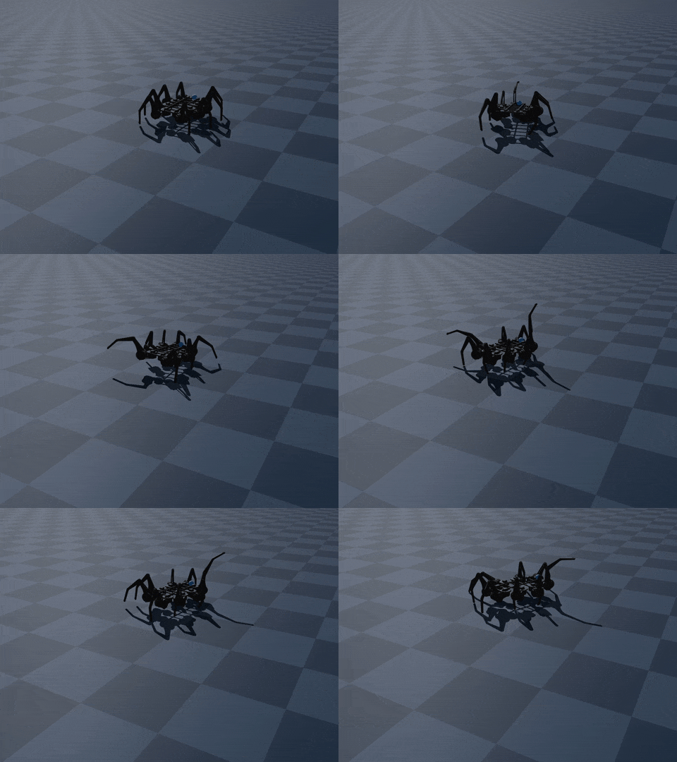
I started simple by exporting my robot to Mujoco XML and training it in the Gymnasium environment using StableBaselines3. This worked well enough — I got the robot to stand up, but it never truly started walking. I realized I'd need to graduate to a more capable system to get much further.
![]()
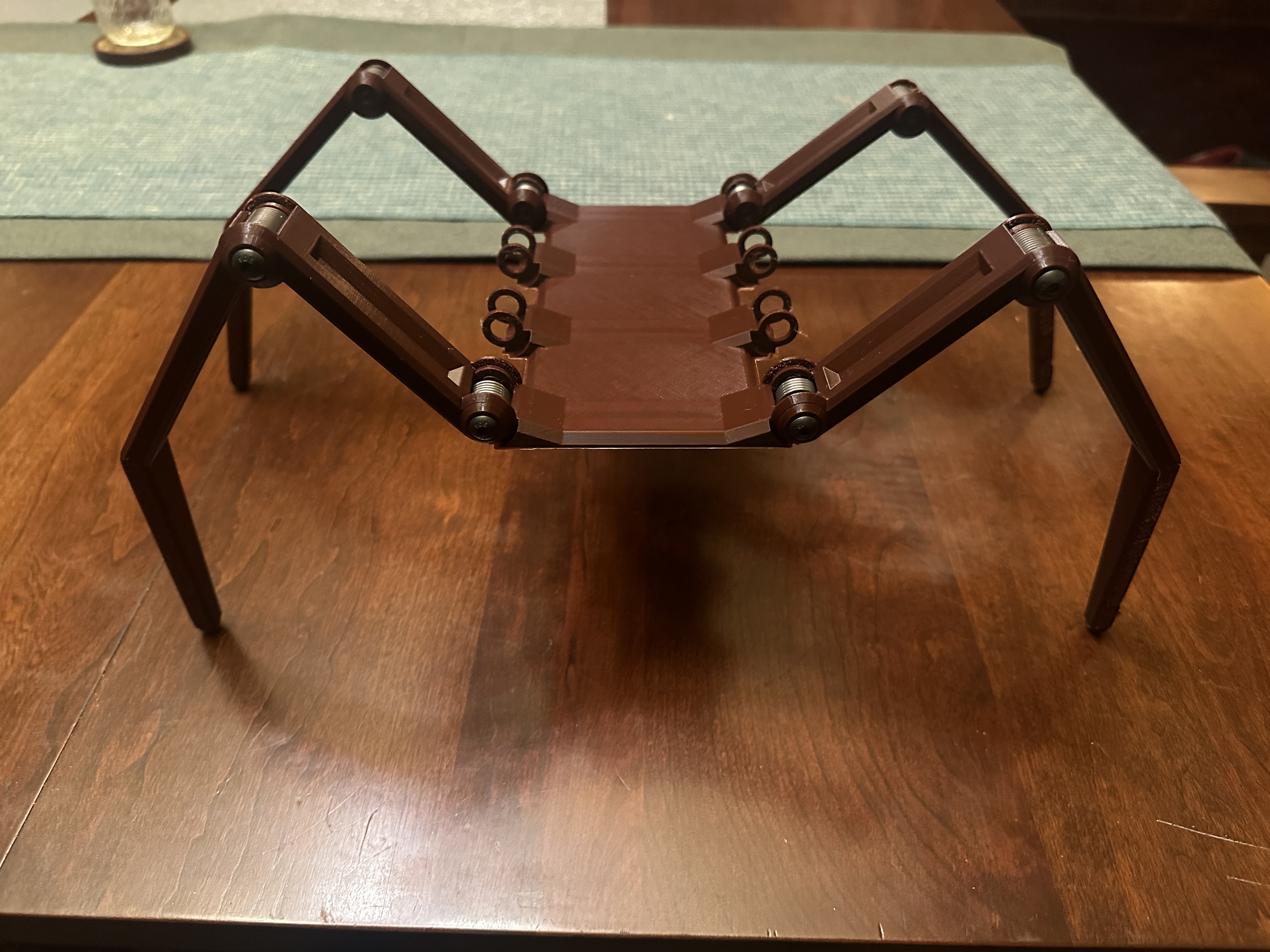
I liked to call this the drunken spider.
Isaac Lab - so much promise...
The more I researched reinforcement learning, the more I encountered people talking about NVIDIA IsaacLab. It's a feature-rich platform that runs training directly on NVIDIA GPUs, enabling thousands of simultaneous training environments.
I spent months working with it. Countless hours converting my robot model from intuitive mujoco XML to the more complex USD format. I built various environments and tweaked settings, but my spider wasn't learning.
![]()
It turned out that my simulator was perpetually unstable, and the robots would randomly explode off the ground.
I scoured the documentation and tried everything that was supposed to help with simulation stability. I opened discussion threads asking for help, which went unanswered.
Finally, in mid-August, I abandoned IsaacLab.
Genesis: A fresh start
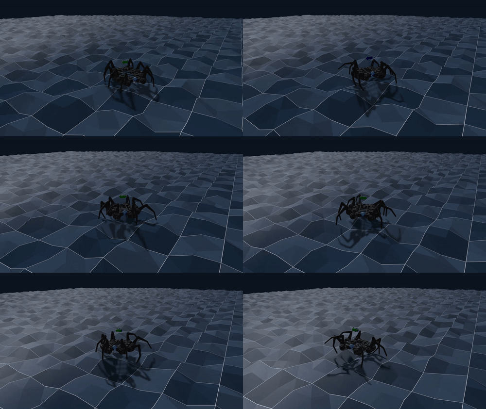
Enter Genesis — a new robotics simulator with its first commit in December 2024. It boasts being cross-platform, 100% Python, and faster than any other simulator around. After a few days getting familiar with it, within a week, my robot was not only standing up but taking its first steps!
![]()
Genesis deserves serious credit. Not only is their simulation platform outstanding, and their development team is incredibly active on GitHub. They respond to questions, fix bugs, and constantly add performance improvements to make training even faster!
Despite all this, I missed some of the IsaacLab ecosystem. Genesis is a simulator, optimized for parallel environments, not a training ecosystem. IsaacLab, on the other hand, provides a library of composable blocks that abstract away the implementation details, leaving just the important bit.
Genesis Forge was born
Taking inspiration from IsaacLab, I started building a series of reusable building blocks for Genesis environments and named this framework Genesis Forge. It has become an end-to-end system for creating robotic training environments in the Genesis simulator, with all the boilerplate handled for you. You can focus on what matters, while keeping your code clean and easy to understand.
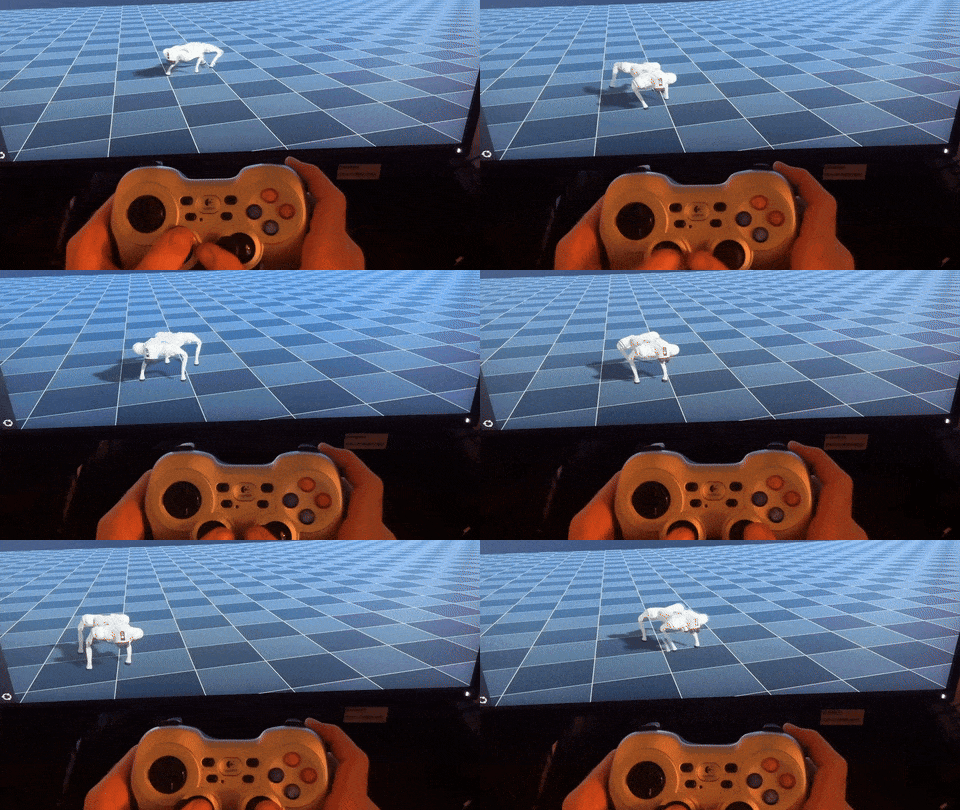
It even has some enhanced features, like being able to "play" your trained robot with a gamepad controller.
![Gamepad controller interface]() What's next?
What's next?Now that I've trained a spider to walk in a simulator, I guess it's time to build the real thing.
I've already built a single leg, so the first thing I want to do is wire the leg up to the computer and have it mirror one of the legs in the simulator. Then I'll put in a very large motor order and attempt to construct the entire thing.
Stay tuned.
-
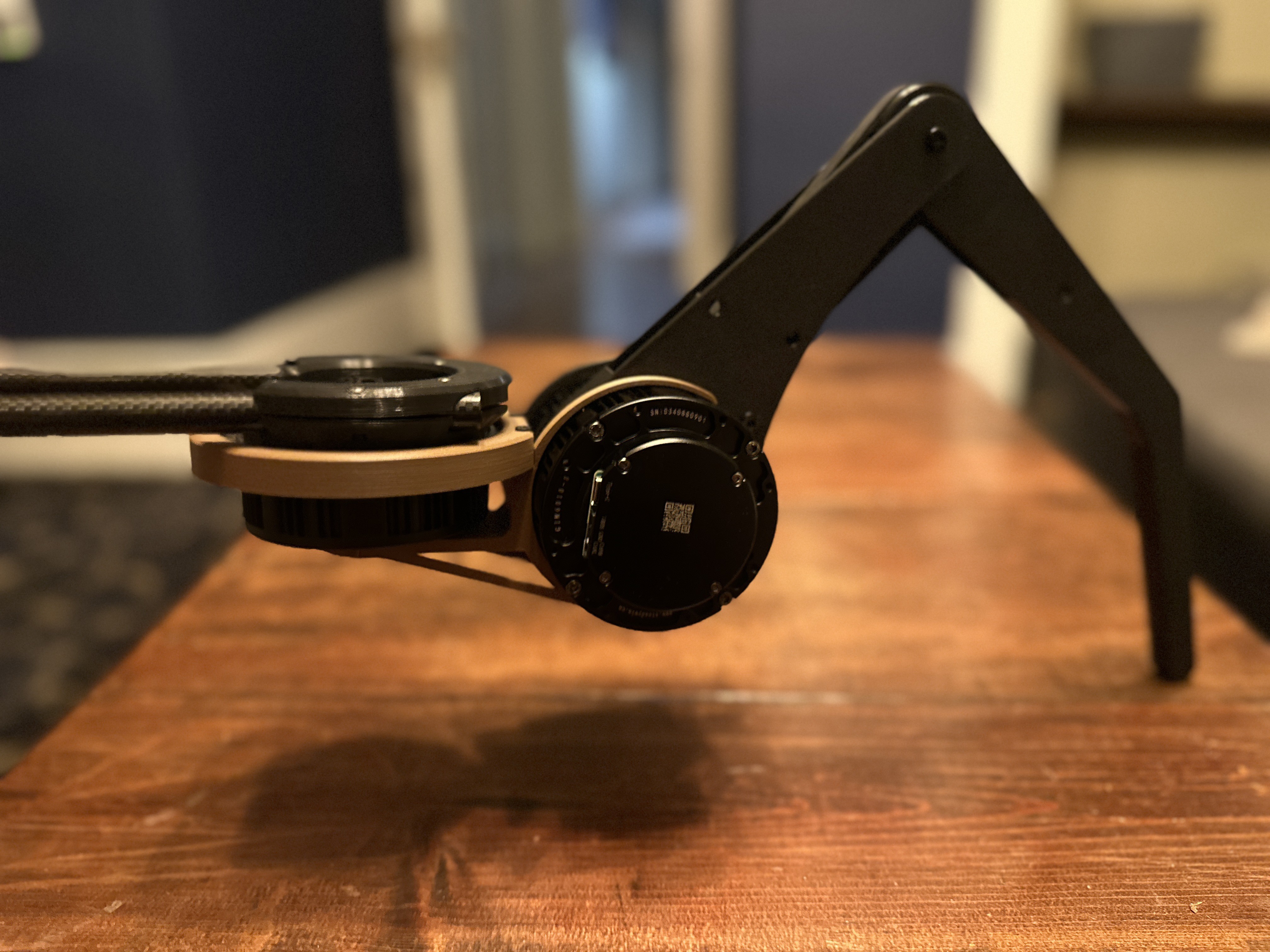
Hip adjustment
06/25/2025 at 06:00 • 1 commentI was never really satisfied with the connection between the hip motor and the leg.
![]()
But it was one of those things that I convinced myself was probably good enough. However, without any additional support, the weight of the leg would likely cause the connection to flex, twist, and pry, possibly leading to failure of the 3D-printed part...
---------- more ----------...and I probably would have moved forward, as-is, until dekutree64 left a comment on my last post, reminding me that this could be a problem (thanks dekutree64!).
I marinated on this for a few weeks while traveling, and on my way home, I came up with a solution.
The ideal solution would be to support the hip attachment symmetrically on the motor, so that the motor is essentially centered on the movement arm. In this configuration, the attachment to the motor output would be on one end, and a free-wheeling bearing would be on the other. The additional bearing would help take the strain off the motor output connection.Luckily, I found a bearing that fit perfectly snug around the top of the motor down to the heat sink fins. Then it was just a matter of reworking the model to integrate the bearing.
Here's the assembly of the updated hip section:
![]()
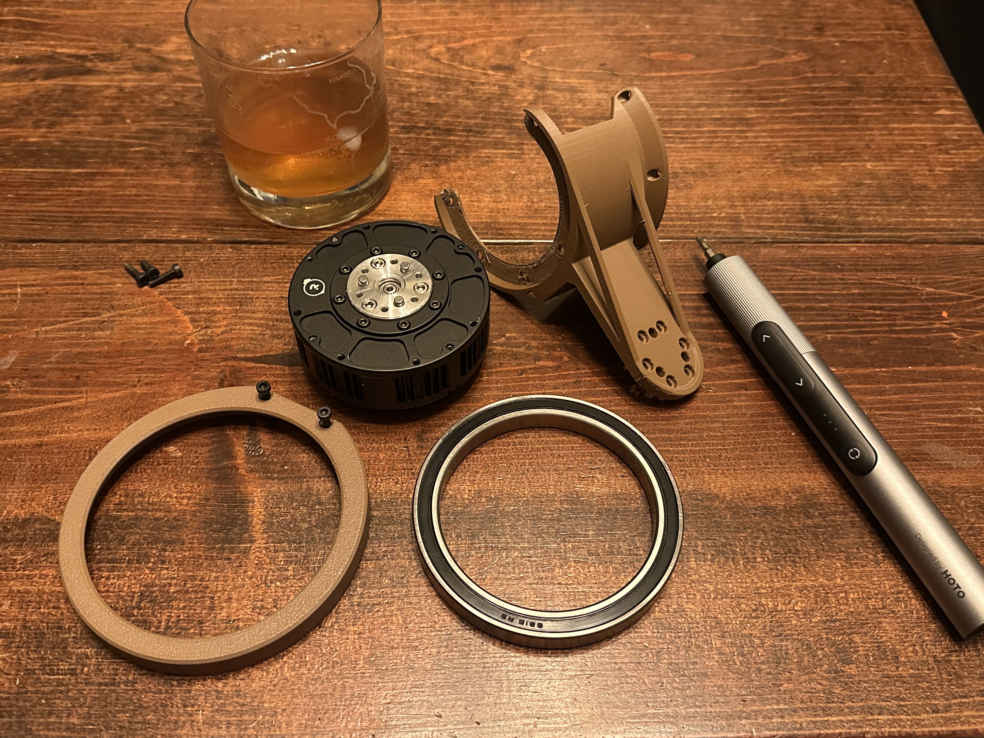
The parts, and a drink essential for assembly ![]()
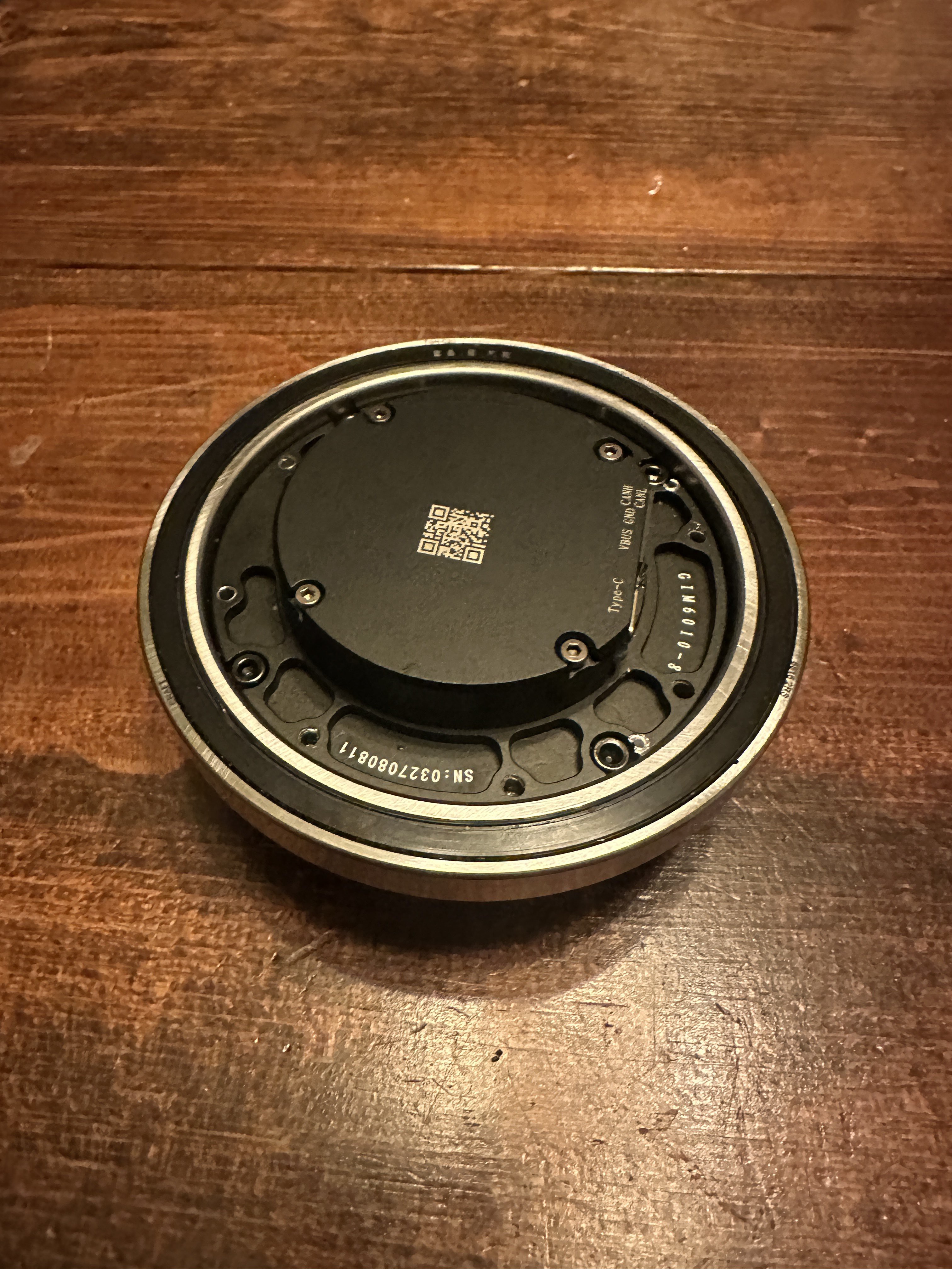
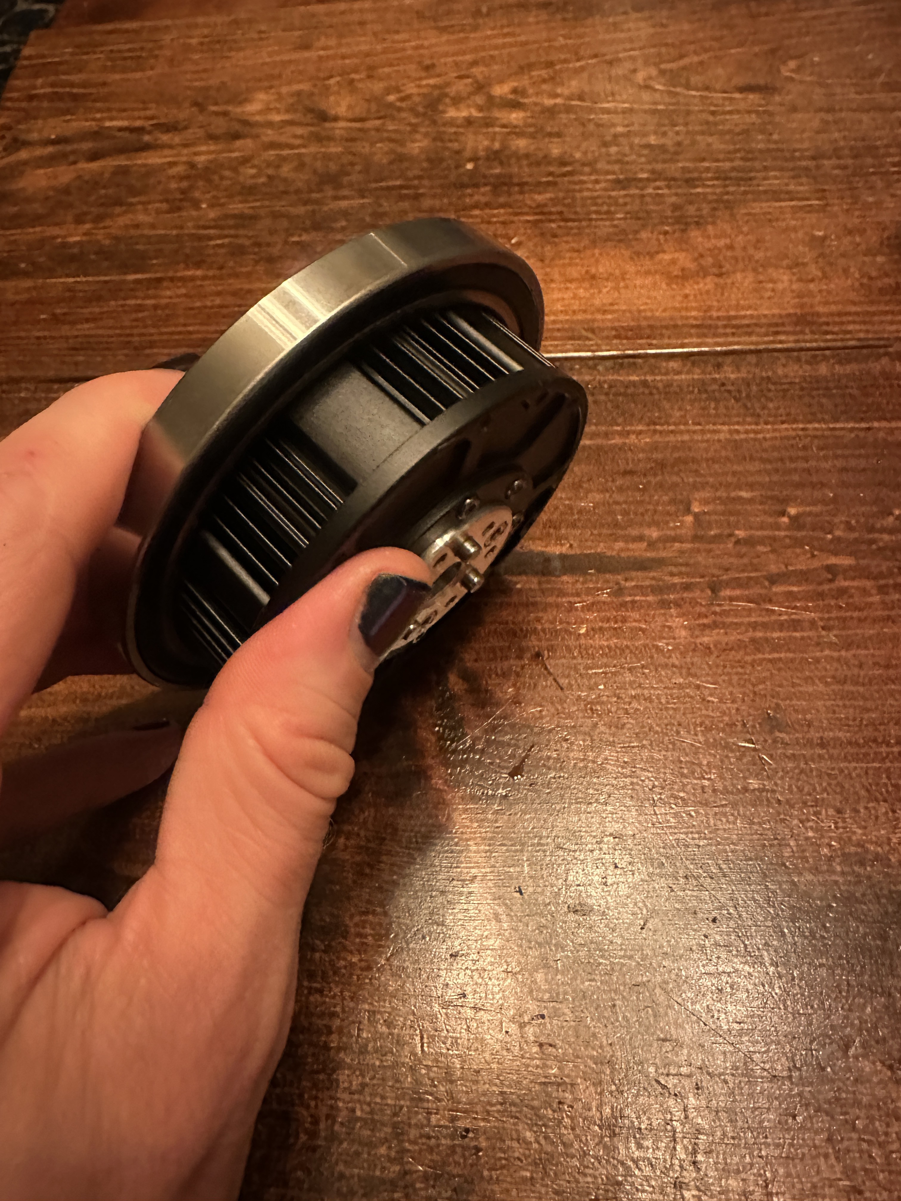
Attach the bearing to the motor ![]()
![]()
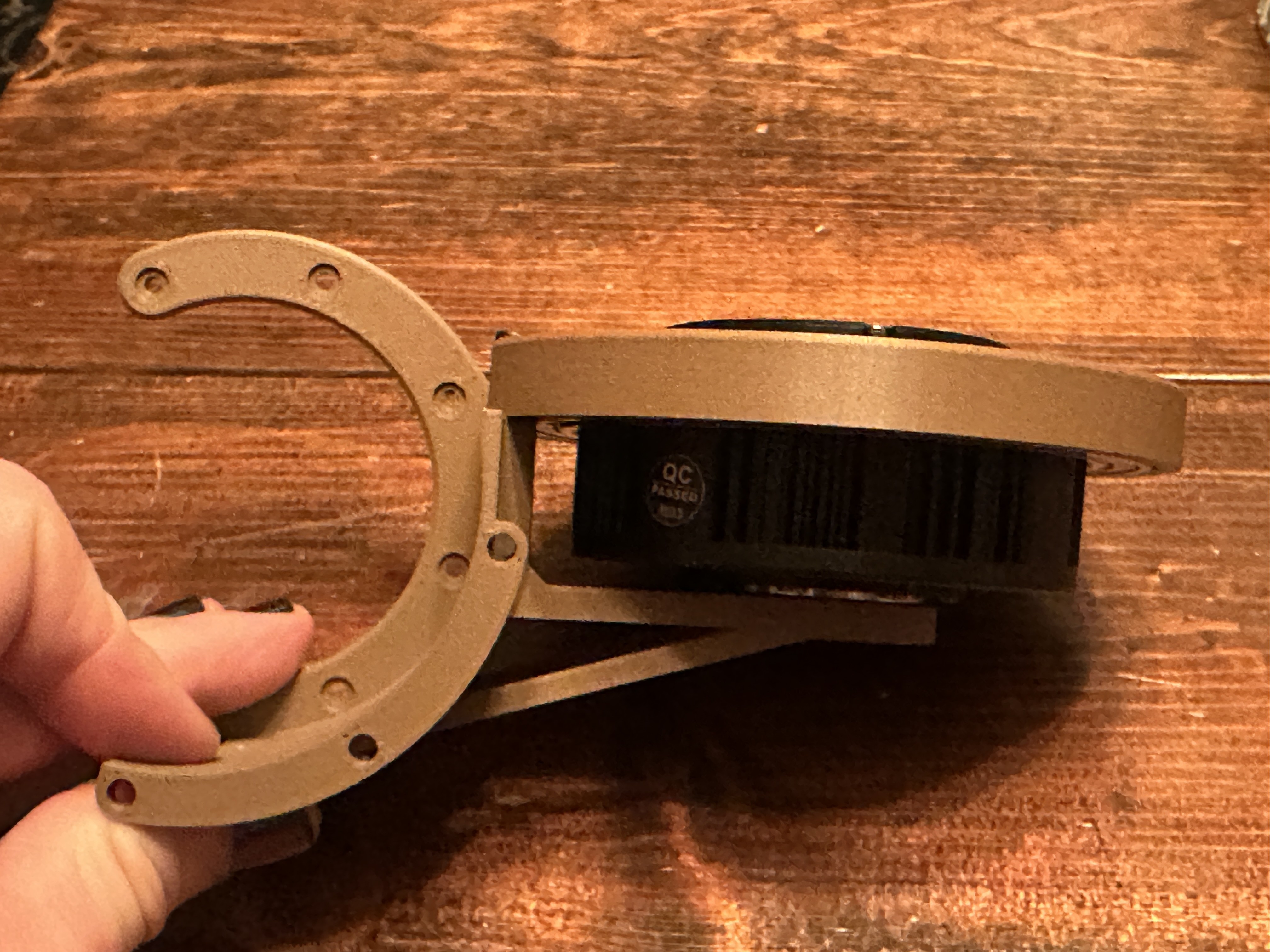
The hip motor assembly All together
Here's what the updated leg looks like.
![]()
What's next?
I've also been working on converting my CAD model into a robot simulator format (mujoco MJCF) so I can use reinforcement learning to train it to walk. I found a great Autodesk Fusion plugin called ACDC4Robot, which converts CAD models into robot definitions. I had to modify it (and submitted a pull request) to work for my model, as I'm using nested components and as-built joints.
The next steps are to finalize the CAD export, build the reinforcement learning training code, and start the process of teaching it to walk. Stay tuned...
-
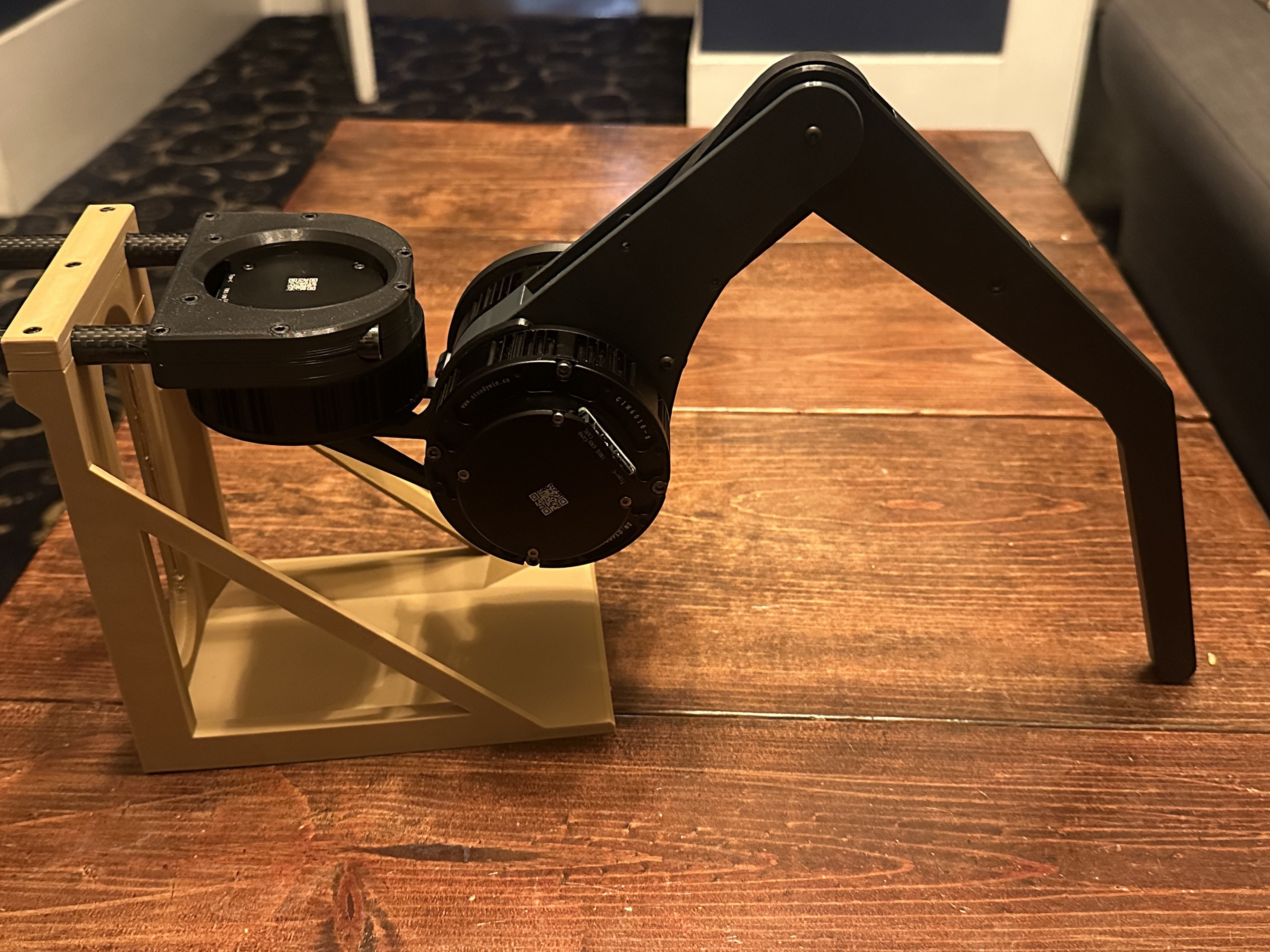
One leg complete...now to walk
05/06/2025 at 04:58 • 7 commentsAfter countless iterations and so many 3D printed parts, I have a leg that I'm (mostly) happy with.
![]() ---------- more ----------
---------- more ----------Here's a short video showing its range of motions.
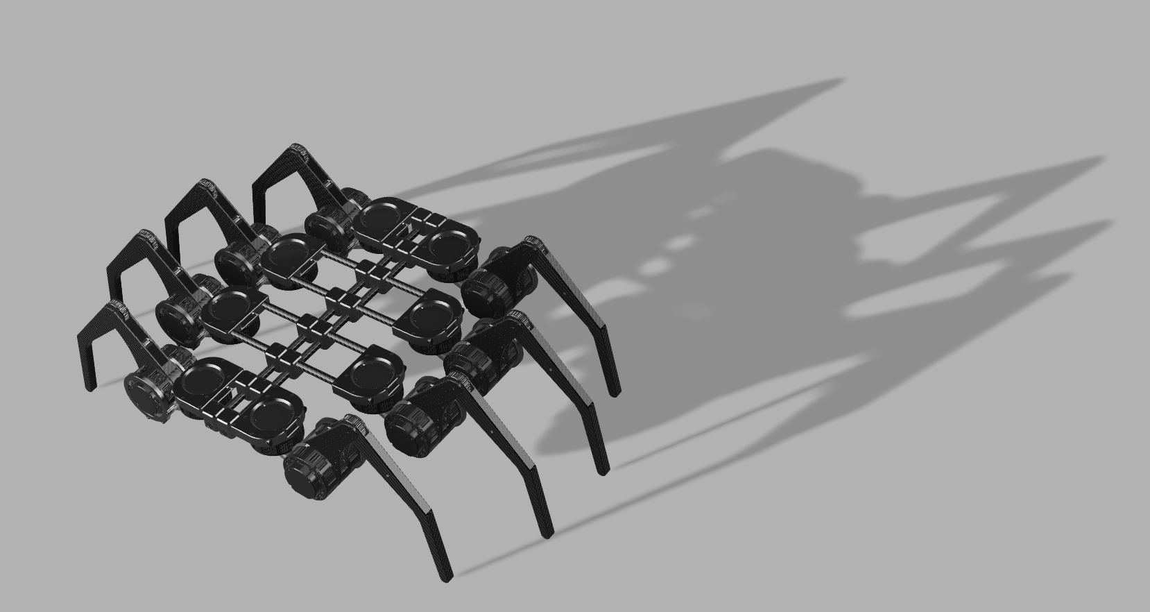
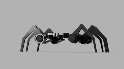
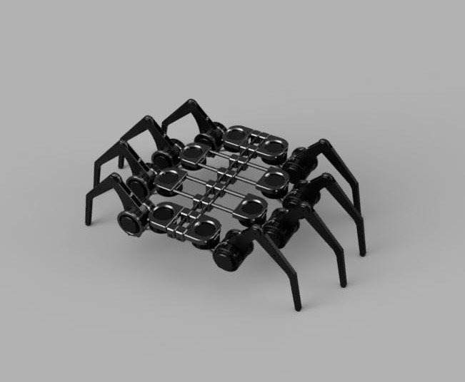
Now that I have the first leg at a good place, I've put together a simplified design of what the body structure will look like.
![]()
![]()
![]()
Interactive CAD version
Here's a leg section in an interactive CAD browser:
Teach it to walk
The next step is to get this into a simulator. I plan to use reinforcement learning, either in Gymnasium or NVIDIA Isaac Lab, to teach it to walk. Stay tuned.
-
Steadywin GIM6010-8 - Stock controller vs ODrive vs Tinymovr
04/12/2025 at 06:50 • 3 commentsIn my last post, I put a couple of motors head-to-head and decided to move forward with the Steadywin GIM6010-8. Over the last month, I've been testing it with various 3rd party controllers. Here are the contenders:
- Stock motor controller (ODrive 3.6 clone)
- Bare motor + Odrive Micro
- Bare motor + Tinymovr R5.3
- Bare motor + MJBots Moteus C1
![]()
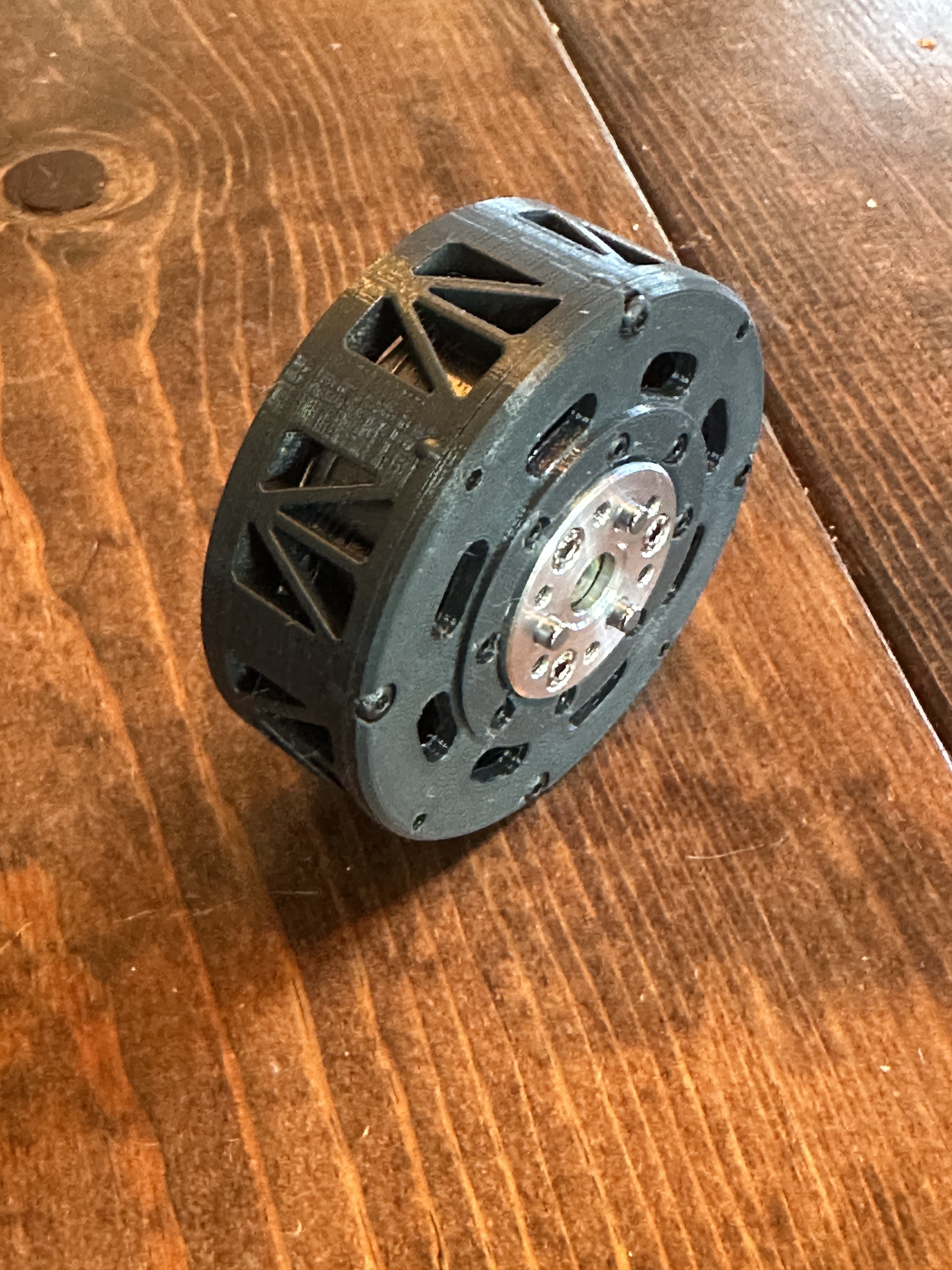
Bare GIM6010-8 with 3D printed shell ---------- more ----------The main reasons to use the bare motor with a 3rd party controller are:
- The bare motor costs less than $50,
- You can design the motor directly into your 3D design, and loose the weight of the aluminum shell.
- You can use the latest and greatest FOC motor technology.
I first heard about this idea when looking at a project by Aaed Musa. However, one thing concerned me. The motor is rated for 11Nm of torque, but Aaed found that it was only producing 3Nm for him. This seemed suspicious since that's so much lower than what's listed on the product page. I started to suspect that this might be related to his use of the Odrive Micro controllers, which are only rated for 7A, and the motor's maximum current is 25A.
So let's test this theory.
Controller and Torque Testing
![]()
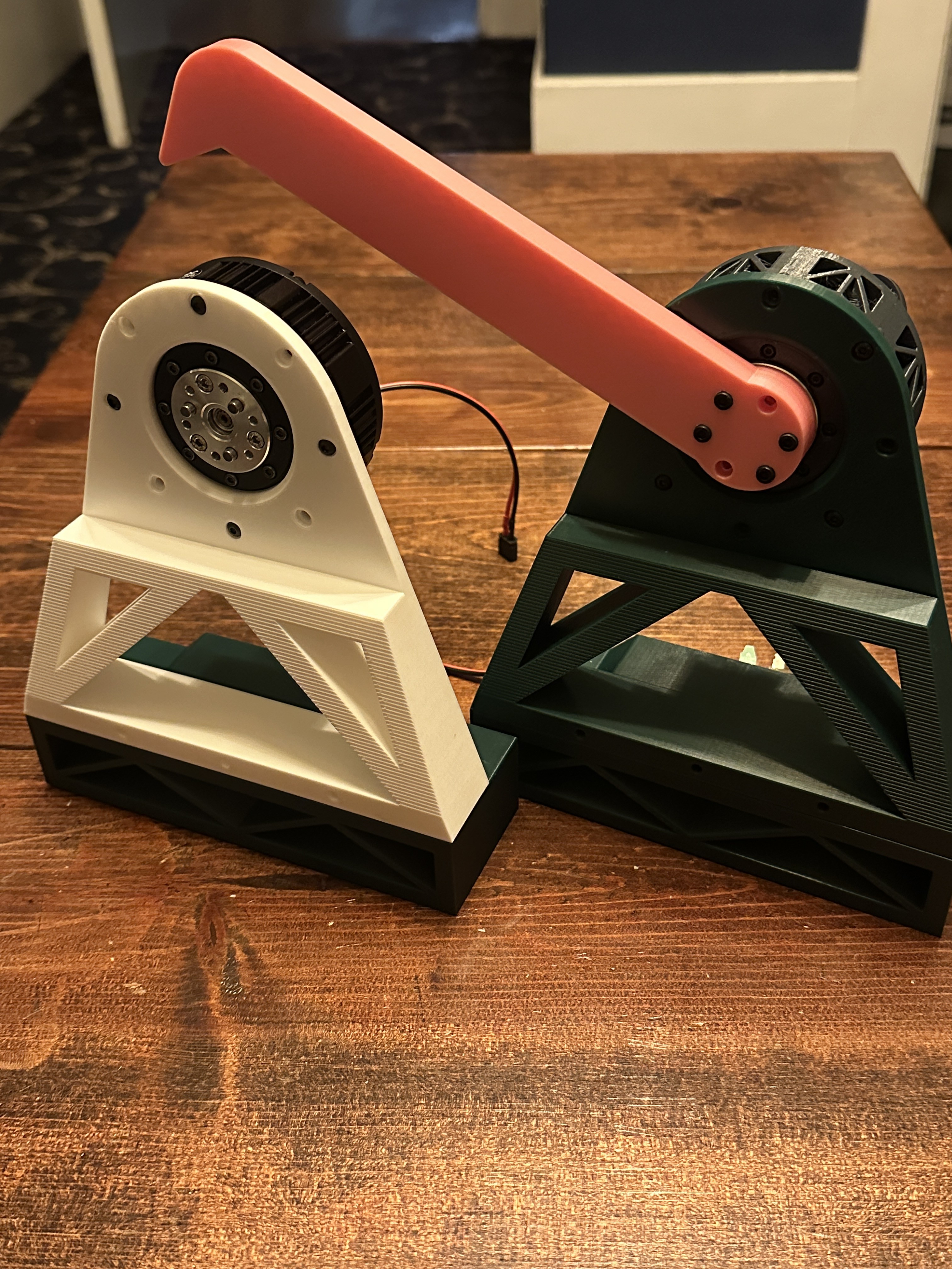
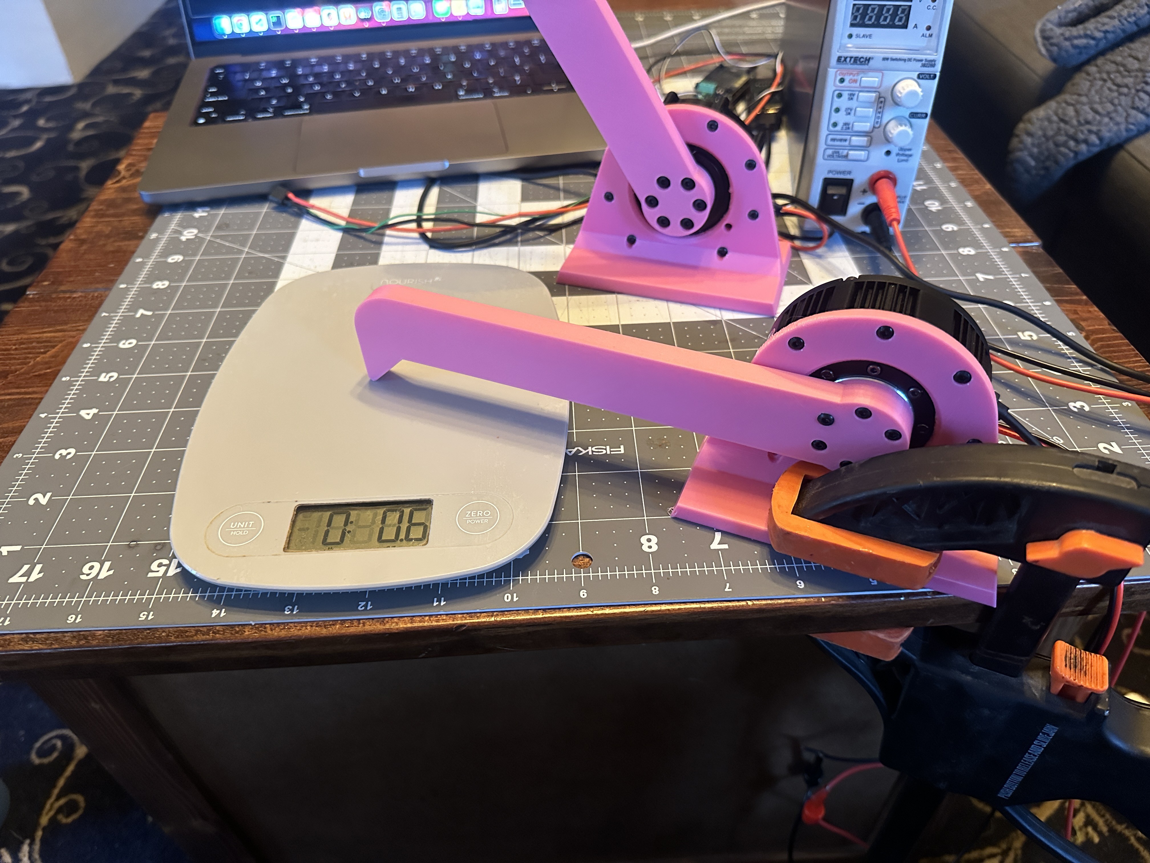
To test all the controllers head-to-head, I ordered a couple of motors from Steadywin: one complete motor + controller + shell, and one bare motor. Then, I designed and 3D-printed a custom enclosure for the bare motor, and set up a test base and a digital load cell.
Stock controller
The stock controller is an ODrive clone running a customized version of the 0.5.x ODrive firmware. ODrive closed the source code to their firmware at version 0.6.0. So you won't get the latest features, but the interface will feel familiar if you've used ODrive before.
So how did it do?
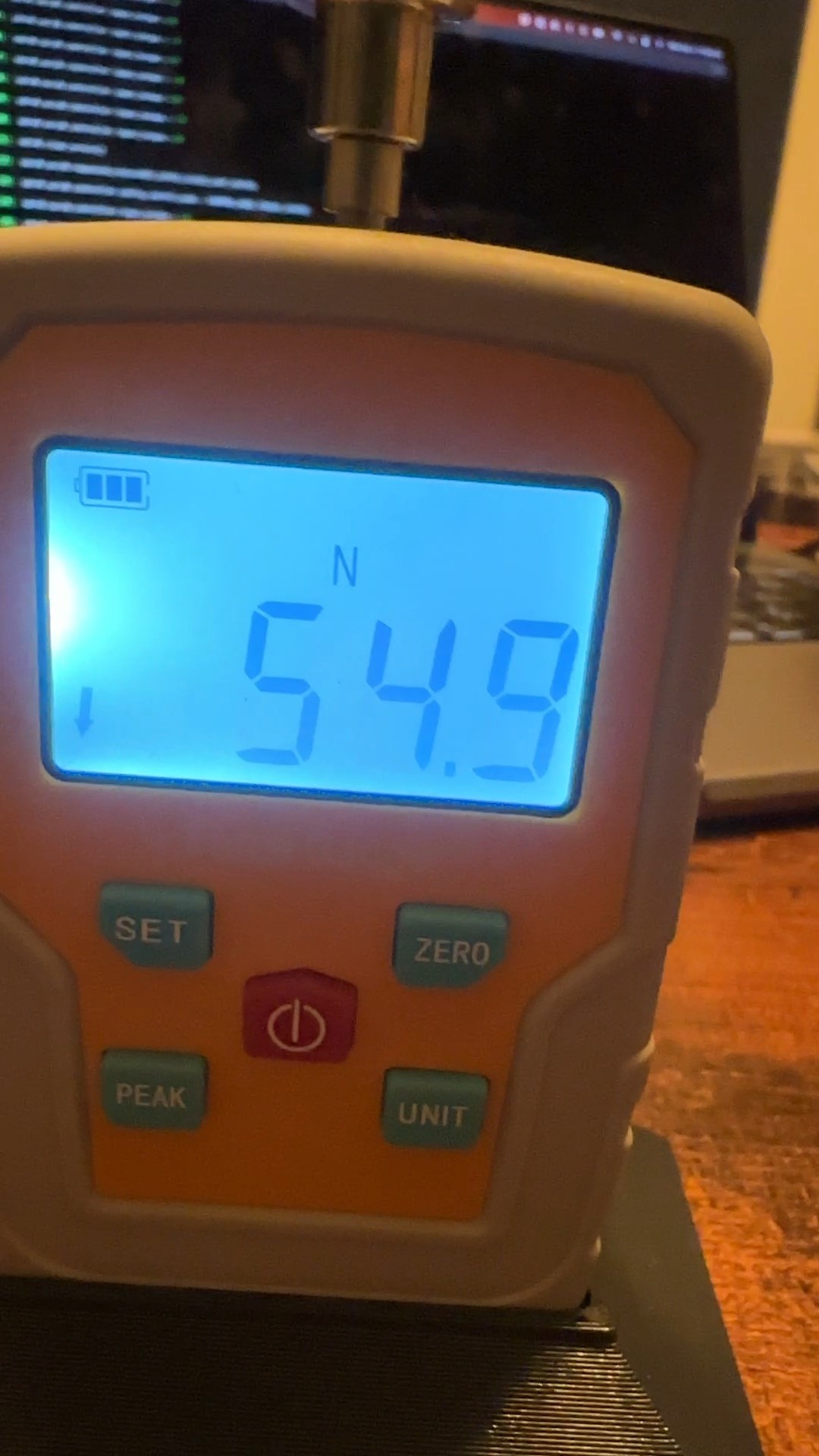
![]()
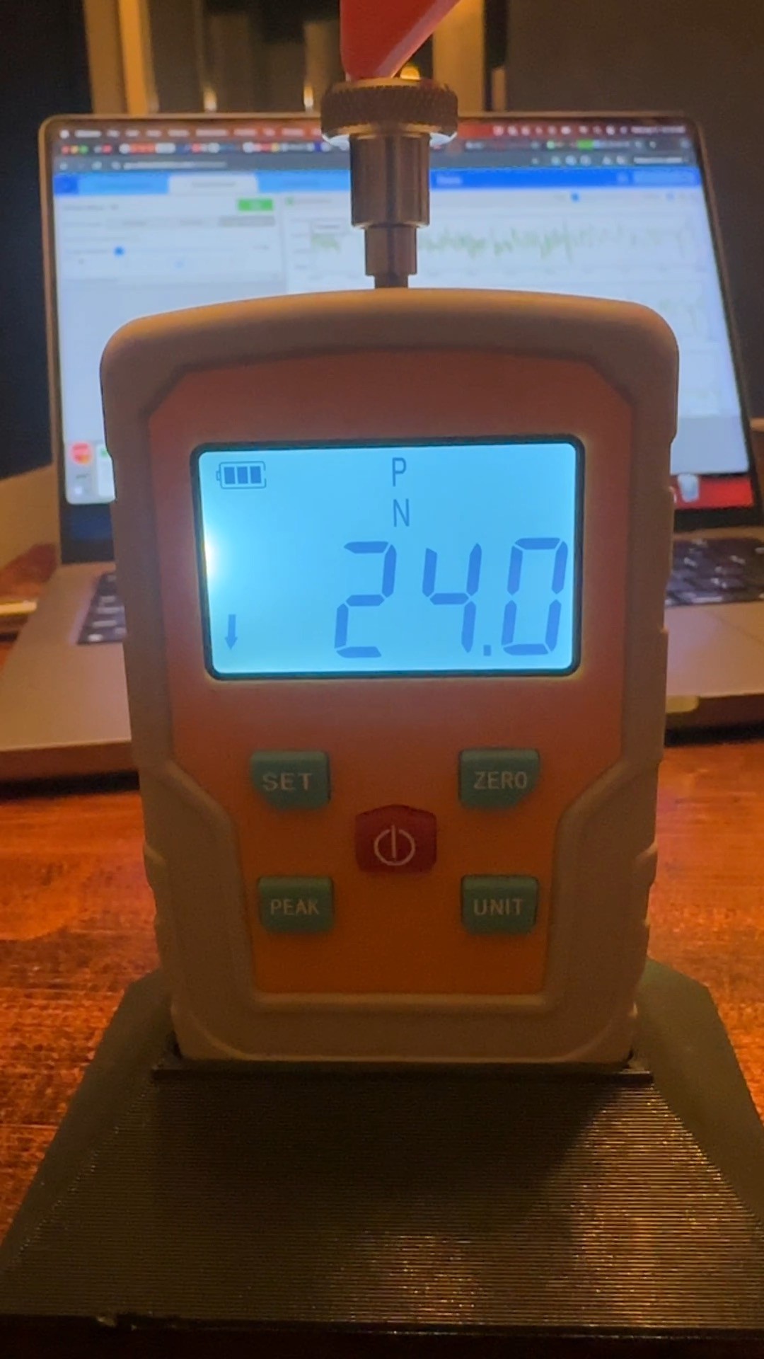
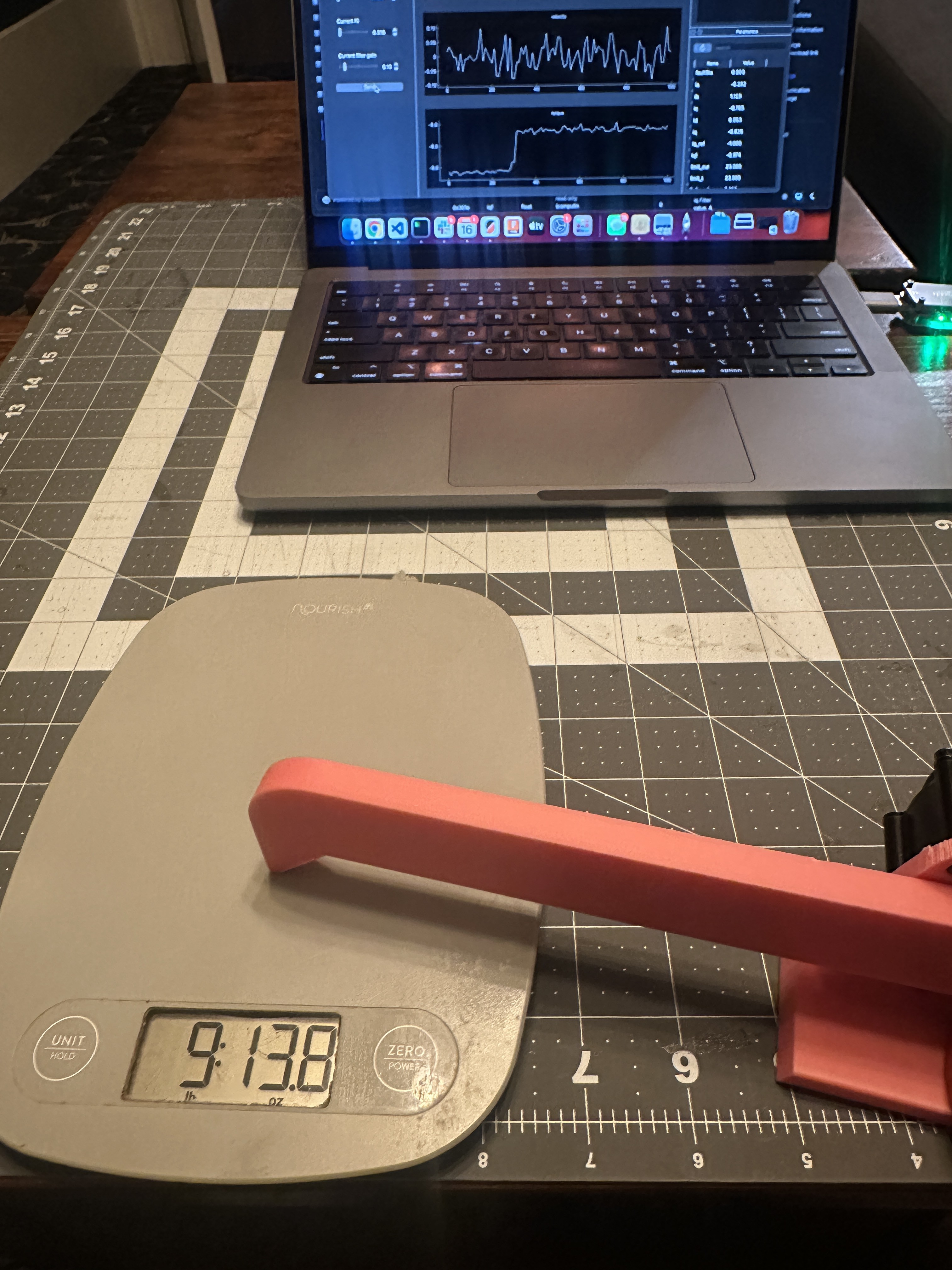
At 24A (a little shy of its maximum current), the stall force fluctuated around 55N at the end of a 200mm arm. To convert that to Nm, we multiply that by 0.2M and get 11Nm!
So with the stock controller, we can get the full force potential promised by the manufacturer.
ODrive Micro
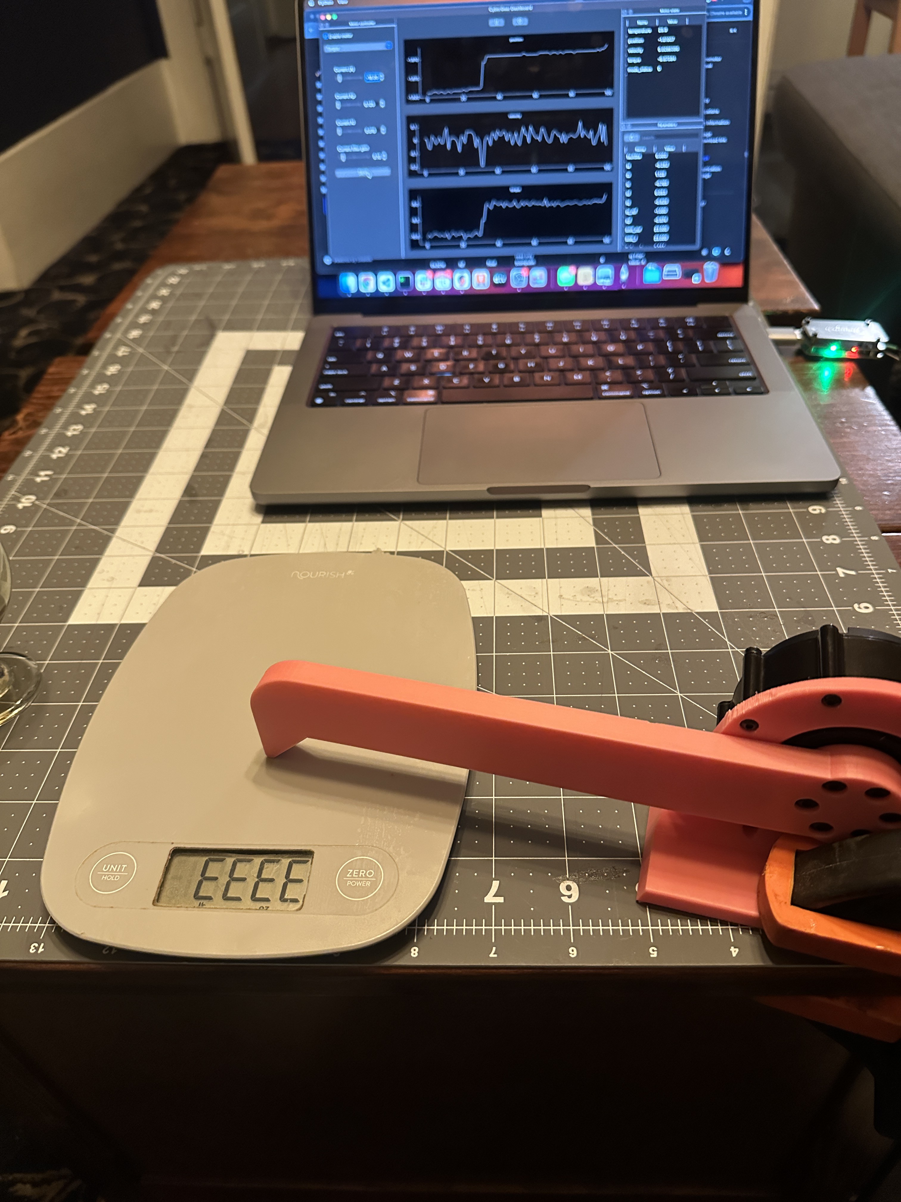
With the ODrive micro, we get all the latest bells and whistles. However, when testing the maximum stall torque, we only got 24N, which converts to 4.8Nm
![]()
Tinymovr R5.3
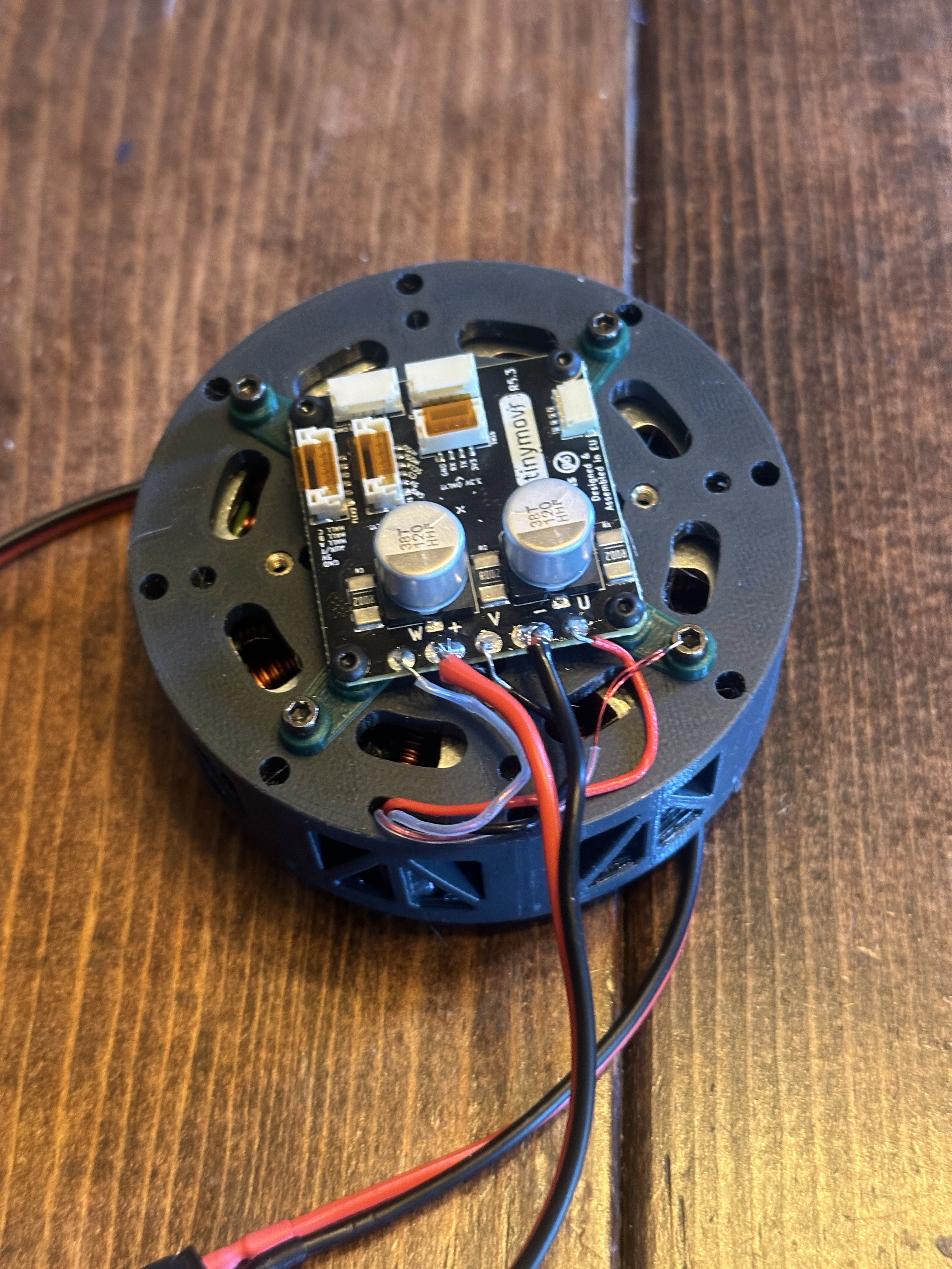
I kinda love this little board. Not only is it small and easy to use, but their documentation is very well written.
But how does it torque?
![]()
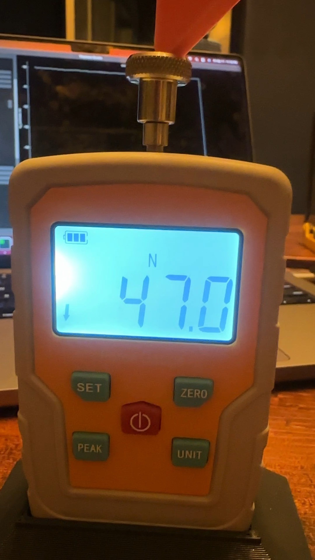
At 15A, it was pushing 47N or 9.4N! Unfortunately, I started hearing cracking from my test base, and I didn't think it was safe or prudent to push it any further. But I feel like I could have gotten the whole 11Nm out of it.
Seriously, this is a great little board.
![]()
Nonstarter: MJBots Moteus C1
I really wanted to like the moteus C1 controller. It's open source and sold at a great price. There's so much to love. Unfortunately, I couldn't even get the GIM6010-8 motor spinning on it. I purchased the entire motor development kit to familiarize myself with the controller and got their motor spinning just fine.
I spent a little time trying to troubleshoot the issues, but I gave up without much useful documentation and with clearly easier boards to use. What happens when I run into bigger issues if I can't even get a motor spinning easily?
Conclusion
After trying all the controllers, my favorite was the Tinymovr R5.3 for its ease of use, excellent documentation, and high torque potential. However, paired with the bare motor, the cost is nearly $150 before shipping.
On the other hand, I can buy the motor with the stock controller and shell for ~$85. For just $10 more, I can get the motor with a built-in absolute encoder on the output shaft. This means that, on a cold start, the robot will know the motor's position, without any homing sequences. Before shipping, this totals to only ~$95 (motor + shell + controller + second encoder).
I've decided to use the stock controller and built-in second encoder for this project. I've just ordered a couple of them and am starting to prototype the first of the eight legs. Stay tuned!
3D Model
You can download the 3D models I created for the motor shell from printables.
-
Steadywin GIM6010-8 v.s. Xiaomi CyberGear Micromotor
03/17/2025 at 22:52 • 3 commentsContinuing from my last post, I'm trying to narrow down which actuators to use for the spider bot and I've narrowed it down to the Steadywin GIM6010-8 and the Xiaomi CyberGear.
Here's how they compare:
---------- more ----------CyberGear GIM6010-8 Size 80.5mm x 36.5mm 80mm x 40mm Weight 317g 388g Max RPM 296RPM 420RPM Gear reduction 7.75 : 1 8 : 1 Nominal Torque 4Nm 5Nm Max Torque 12Nm 11Nm Torque constant 0.87Nm/A 0.47Nm/A Cost $91 $50 - $85 Driver Proprietary with minimal documentation ODrive 3.6 compatible clone. Lots of documentation + community. Driving the motor
The first problem I ran into was driving the CyberGear motor. It has a proprietary CAN bus communication scheme and very minimal documentation. They do have a desktop software program to connect and configure the motor, but it only runs on Windows with a very specific USB CAN adapter (not included with the motor). I'm on a Mac and wasn't able to get it working.
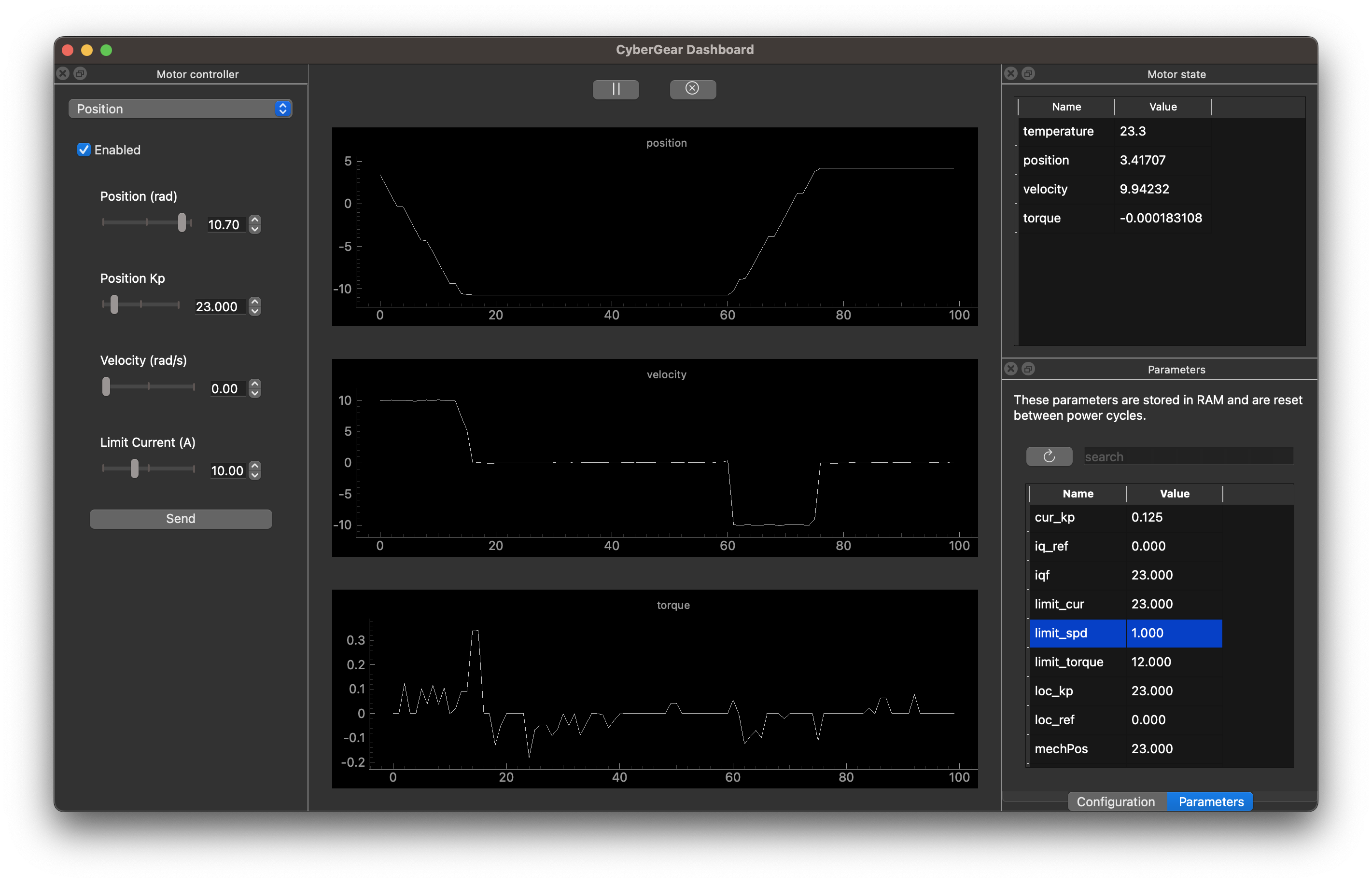
My solution was to build a desktop motor control app from scratch in Python that should work on all platforms.
![]()
On the other hand, the GIM6010-8 motor uses an ODrive-compatible driver. This means there's plenty of documentation on how to drive it and a community of people to answer questions.
Stall torque testing
While reading about Aaed Musa's Impulse project, he mentions that the measured stall torque of the GI6010-8 was only 3Nm, vs the advertised 11Nm. That would be way too little for my project if that's true.
Let's put the two motors to the test.
![]()
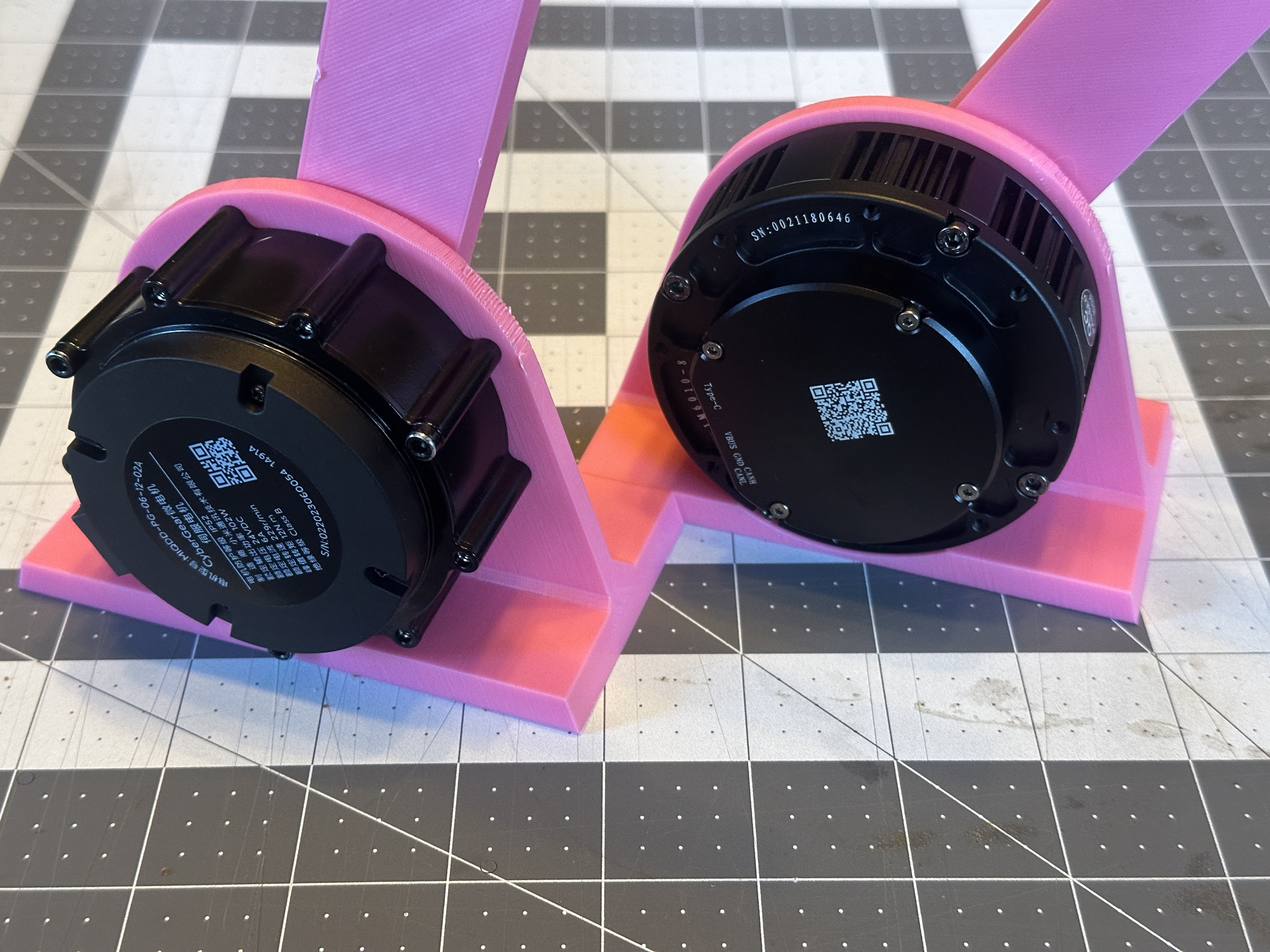
I 3D printed a matching test stand for each motor with a 200mm arm that would press down against a basic kitchen scale to test this.
![]()
![]()
My scale tops out at 11lbs, and both motors were able to push it to the limit.
To break down what that means in Nm:
- 1 lb = 4.44822N
- 11 lbs = 11 × 4.44822 = 48.93042N
- 200 mm = 0.2 m
- Torque = 48.93042 N × 0.2 m = 10.676 Nm
For each motor, I wasn't even driving them at 100%. So, I assume they can meet the torque listed on their product sheets.
I'm not sure why Aaed Musa got different results. Perhaps the GIM6010-8 has improved since he tested it. Alternatively, he used an ODrive micro instead of the stock driver in his tests. This driver is listed to have a max power output of 7A, while the motor's max consumption is listed at 25A. Perhaps the ODrive micro was limiting the torque to keep the current within the limits.
Stall torque current
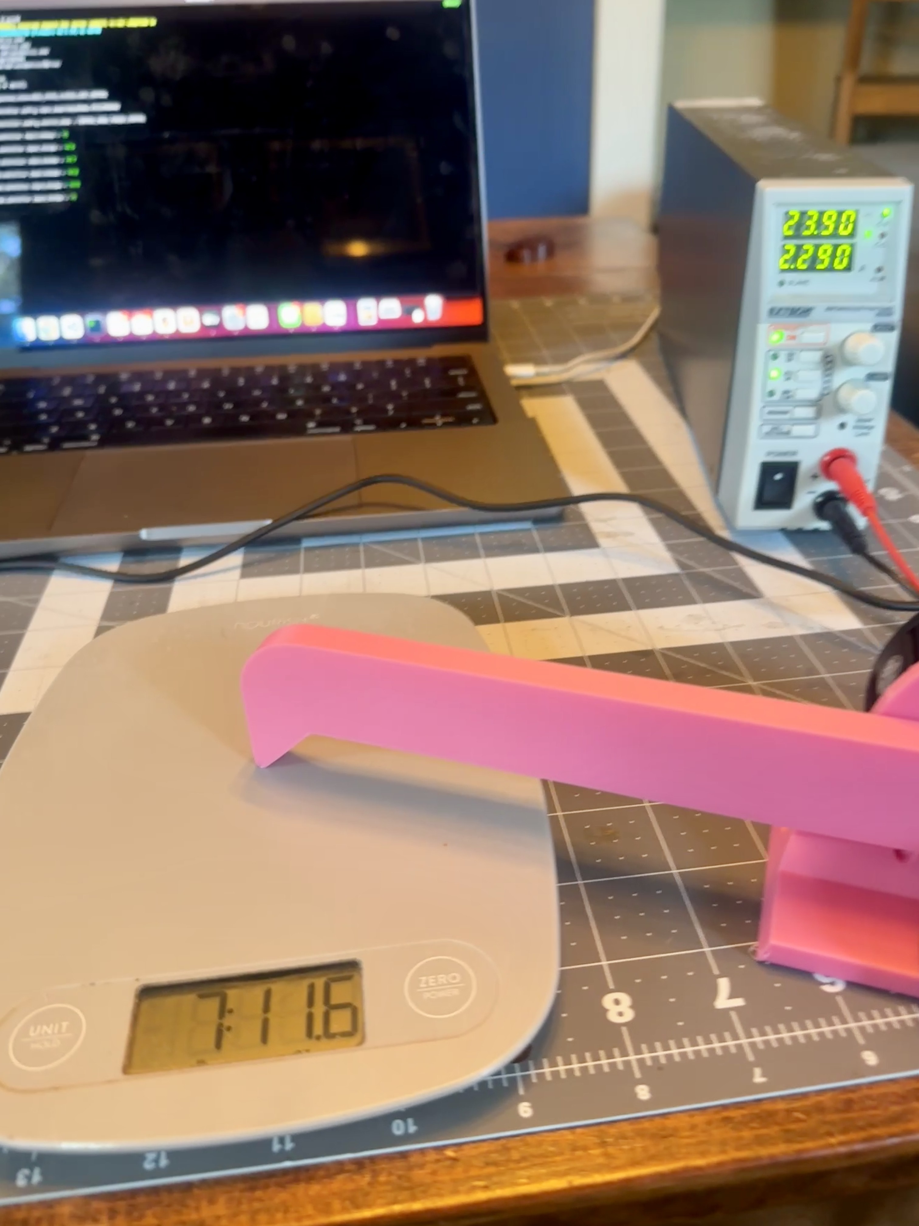
Next, I wanted to see how the current consumption compared. For this test, I had both motors press down with the same amount of force on the scale and measured the current.
![]()
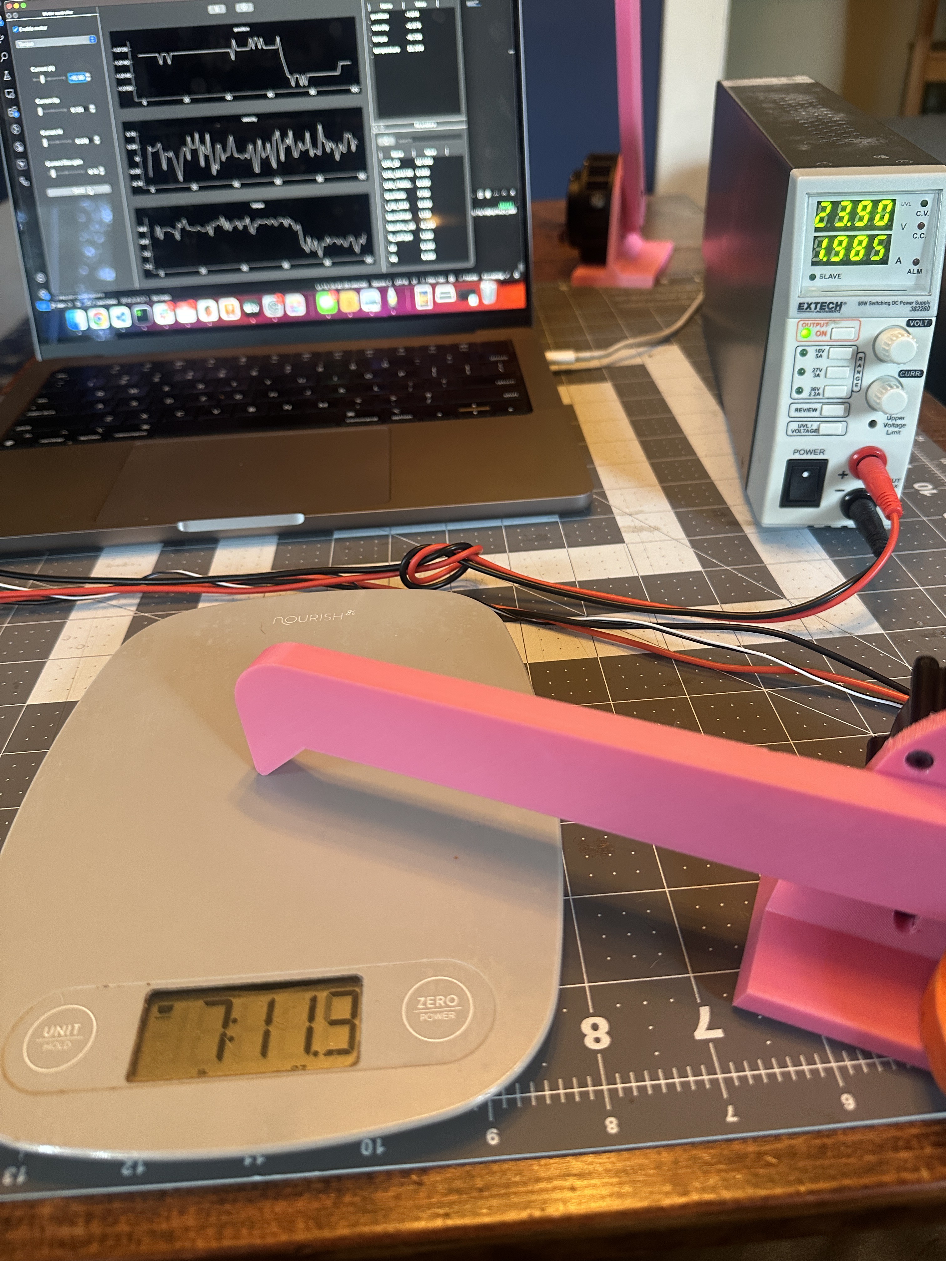
GIM6010-8 - 2.29A at ~7lbs 11oz ![]()
CyberGear - 1.99A at 7lbs 11oz With both motors pressing at around 7lbs, 11oz, the GIM6010 pulled 2.29A and the CyberGear 1.99A. So, the CyberGear has about 13% more stall torque per amp.
Sound
Motor sound might seem like an odd thing to consider, but it's important since my robot will have 24 of them. When the CyberGear motor is enabled, it makes a very noticeable noise, like an airplane taking off. This is common with FOC controllers as they send current to the coils to maintain the state. The GIM6010 motor also has a sound, but it's about half the volume.
Usually, this can be fixed with calibration and tuning. On the CyberGear, adjusting the Kp and Kd values can make the noise quieter or louder. However, I haven't found a combination of tuning values that brings the noise level down to the GIM6010, and the motor's documentation doesn't help here.
Second encoder expansion
My robot needs to know where each actuator is at any given time. The onboard encoders in each actuator are placed before the planetary gearbox and used for motor commutation. This means we can't use them to get the absolute position of the motor output.
Some motor controllers have pins for a second encoder and use it to zero the relative position of the motor on startup. Then, even if the motor is moved when the power is off, it'll know exactly where it's positioned when it powers back up.
CyberGear does not support a second encoder, but it looks like the GIM6010-8 does! However, the GIM6010-8 only supports i2c and UART encoder interfaces, which are less common (odrive prefers SPI and RS485).
Alternatively, for $50, I can buy the GIM6010-8 motor without the controller board and attach a $89 ODrive micro, which has more modern support for a second encoder.
Conclusion
By the numbers, the motors are very similar.
The CyberGear is a little lighter and has more torque per amp. However, the onboard controller is poorly documented and has no room for expansion. Additionally, there's no community for support when running into issues.
On the other hand, even though the GIM6010-8 is a little heavier and current thirsty, the driver is based on an older version of a well-known driver (ODrive) with an active community.
I plan to buy the bare GIM6010-8, without the driver board or shell ($49.90), and use an ODrive micro ($89) to drive it. This should give me the latest ODrive offers with an active community for questions.
Addendum: MJBot Moteus Controller
The MJBots Moteus controllers have also been on my radar. The great thing about them is that they are fully open-source and significantly cheaper than the ODrive controllers. During the process of comparing motors, I tried out their development kit. I like the form factor and power output, but I had some problems.
First, the getting started documentation leaves a lot to be desired. It should get you from zero to moving the motor. Instead, it describes the control algorithm at a high level and directs you to the API documentation. This left a bad taste in my mouth that I would have limited support if I ran into issues.
The second and more significant issue is that the motor was about as loud as the CyberGear motor/driver when the Moteus controller was enabled. They have a blog post describing how to tune the controller to be quieter, but I couldn't improve it by much.
That said, I'm still keeping the controller on my radar. I'm concerned that the 7A max current on the ODrive micro might not be enough for more dynamic movements, like jumping. If that becomes an issue in some of my upcoming isolated tests, I'll explore the MJBots moteus line of controllers more.
-
Motors, motors, motors
03/17/2025 at 22:40 • 0 commentsI've spent the last couple of months buried in motors.

A few of the motors I've been testing I've been hunting for the perfect motor with a sweet spot of weight, power, and cost.
---------- more ----------The sweet spot
- Torque: 10Nm+
- Size: smaller than 85mm diameter x 50mm thick
- Weight: under 400g
- Cost: under $150
Torque
The spider will have a whopping 24 motors!!! That's divided up into three motors in each of the eight legs. I'm assuming the robot will weigh between 20 - 30 lbs, so my back-of-the-napkin calculations say that each motor should have 4-6Nm of stall torque. I'm assuming the motors would need at least twice that to jump, plus a relatively high RPM.
These are all rough estimates. I've never built something like this before and welcome any feedback on my assumptions.
Size/Weight
To keep the robot's weight under 30 lbs, I need to keep the weight of each motor under 400g.
I also want to keep the motors as small as possible to keep the overall robot size manageable. The bigger the robot, the stronger the legs need to support it.
Cost
With 24 motors, the robot gets expensive fast. There are many sexy and expensive quasi-direct drive actuators on the market. But for my budget, $150 is expensive but workable.
The standout options
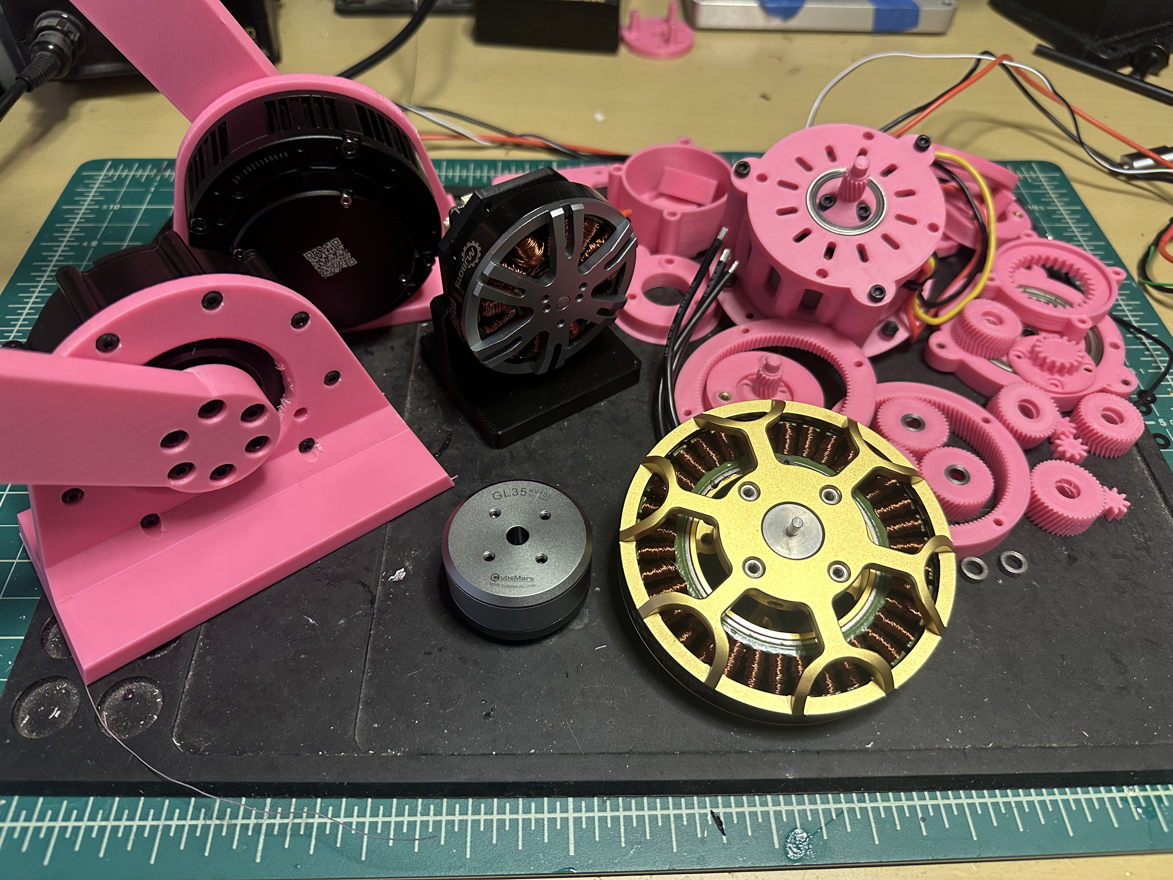
I started by looking at homebrew designs, like building a motor + planetary gearbox around a frameless motor. After many iterations, the results were good, but the cost, torque, and weight did not match that of off-the-shelf quasi-direct drive actuators (more on those, below).
Then I looked into capstan drive systems with motors like the GL35 and the eagle power 8308. These either didn't provide comparable RPM and torque to off-the-shelf quasi-direct drive actuators and would be too big and cumbersome for an eight-legged robot.
At each stage, I kept coming back to these off-the-shelf quasi-direct drive actuators:
The quasi-direct drive actuators
Off-the-shelf quasi-direct drive actuators have built-in gear reductions between 8:1 and 10:1, giving them high torque and responsive RPM. These actuators usually put the planetary gearbox inside the motor stator, keeping the overall motor compact.
But this all comes for a price, and many of these actuators are beyond my budget. However, I found two that fell right into the sweet spot of price and stats: the Steadywin GIM6010-8 and the Xiaomi CyberGear.

CyberGear and Steadywin GIM6010-8 Now, to choose which one to use.
In the next post, I'll go into greater detail, but here's the high-level comparison:
- Size: similar size to each other
- Torque: similar stall torque (11 - 12Nm).
- Weight: CyberGear is nearly 70g lighter than the GIM6010-8.
- Torque per Amp: CyberGear has nearly twice the torque per amp (torque constant) at 0.87Nm/A. The torque constant of the GIM6010-8 motor is 0.47Nm/A
- Cost: GIM6010 is a little cheaper as a complete unit and significantly cheaper ($50) when purchased without a driver (i.e. bring your own driver).
- Driver: The GIM6010 uses an ODrive 3.6 compatible clone, which is easily swapped out. The CyberGear has a proprietary driver with minimal documentation and features.
See the tests I put these through in my next post.
-
How spiders move
02/14/2025 at 22:32 • 0 commentsThis project was initially inspired by learning how spider legs move. Relatedly, have you ever wondered why spiders curl up when they die? Let me explain...
For starters, think about how humans move our arms and legs. Each limb, simply put, is moved by two contradicting groups of muscles. To bend in one direction, one muscle group relaxes while the other contracts. To move the other way, the opposite happens.
Spiders don't do that. At each leg joint, spiders have flexors that bend the leg inward. To extend a leg, the spider pushes fluid from its abdomen to specialized sacks inside the joints. As these sacks expand, they push against the leg and extend that segment. An engineering analogy would be an arm that uses hydraulics to extend and springs to contract.
See this in action and how Rice University is using spiders for actuators
What does this mean for the robot?
Loosely modeling real spiders, I plan to put torsion springs in each leg joint for my robot. They will help offset the robot's weight so the motor actuators won't work hard while standing. To extend the leg, the actuators will need to overcome the spring force; however, this moment doesn't need to be rapid or particularly strong. Conversely, having the spring pressure downward means that the actuators will get assistance while pushing down. This should help the spider move quickly and possibly jump. It will also let me use smaller motors with less torque.
I created a simple test platform to test the idea of springs supporting weight.
![]()
![]()
![]()

 What's next?