 James Hutchby - MadLab
For the second version I arranged the noodles in a regular circular pattern around the head and that was more attractive and worked better for more choreographed patterns on the LEDs.
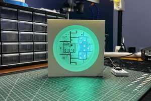
I used KiCad to design the PCB and KiCad’s Image Converter to turn bitmap images of Medusa’s head and the snakes’ heads into KiCad footprints. The output options of this image tool are a little limited though. You can create a footprint for the front solder mask but not for the front copper. However the resulting kicad_mod file is an ASCII text file and can be easily edited to change the layer to F.Cu. I simply duplicated the section defining the image and changed the layer of the copy to front copper. That gave me a KiCad footprint I could place on the PCB with the graphic appearing in exposed copper. For fabrication I selected ENIG and green solder mask which gave an attractive gold appearance.
I wanted a clean top side of the PCB without a legend and without solder joints so used SMT components on the bottom side.
There are twelve noodles in total and the processor I used to control them was an 8-pin part. I used Charlieplexing to allow me to drive that many LEDs with a minimal number of pins. Charlieplexing with N pins allows for the control of N (N – 1) LEDs. So 12 LEDs needed 4 pins. Series resistors limited the current to the LEDs which are rated at 3V.
I used PWM to drive the LEDs which allowed me to set the brightness individually of the noodles in the range 0 to 255 (although practically this only allowed 9 levels of brightness – 1, 2, 4, 8, 16 etc. as a logarithmic scale such as this is needed to give the appearance of being linear in brightness to our eyes). This allowed me to include patterns that faded in and faded out.
I could have illuminated just a single noodle at a time and not used PWM. They would have been brighter but at the cost of only one noodle being on at a time. A PWM approach allowed for more complicated LED patterns but resulted in them being less bright as they are only lit up for 1/12 of the time. But still bright enough I felt.
Power is via USB-C. I used a power-only USB socket as it’s a bit easier to hand solder but it still has 6 pins in a SMT package. There are two ground pins and two Vdd pins because of the symmetrical nature of the USB-C plug but also two CC pins which needed a couple of 5.1k resistors to ground to enable the power supply.
USB-C provides 5V which is not further regulated and supplied directly to the processor.
I used a PIC12F1840 which has 7 kilobytes of flash program memory and is more than enough for a good set of patterns and can run at up to 32MHz (8Mips) which is fast enough for flicker-free PWM over an 8-bit dynamic range. Finally I included an ICSP header to allow programming of the PIC during development and a pushbutton which I ended up not really using.
 Arnov Sharma
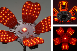
 potblitd
 Natalia
 Alex
Alex