0%
0%
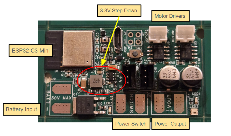
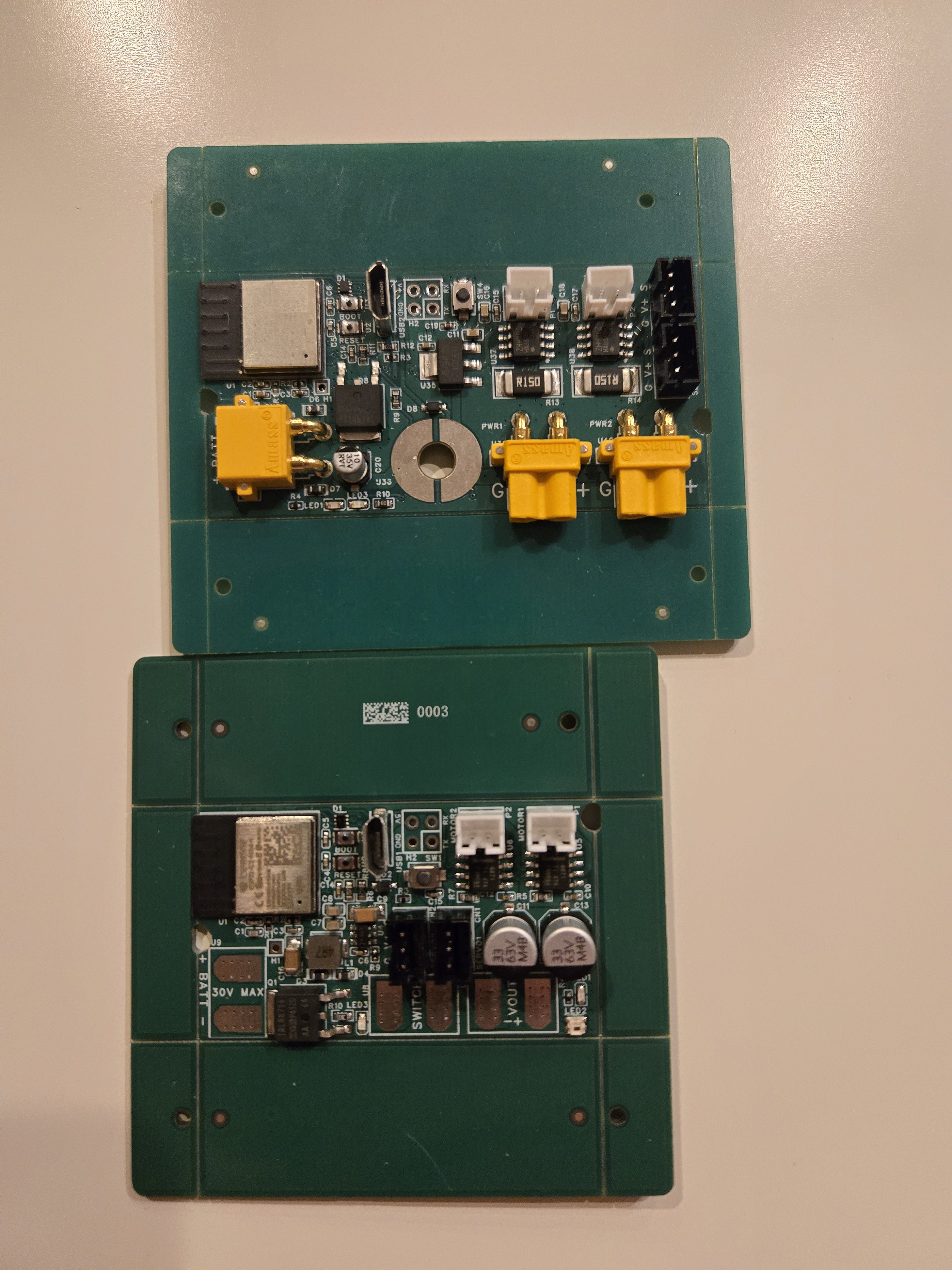
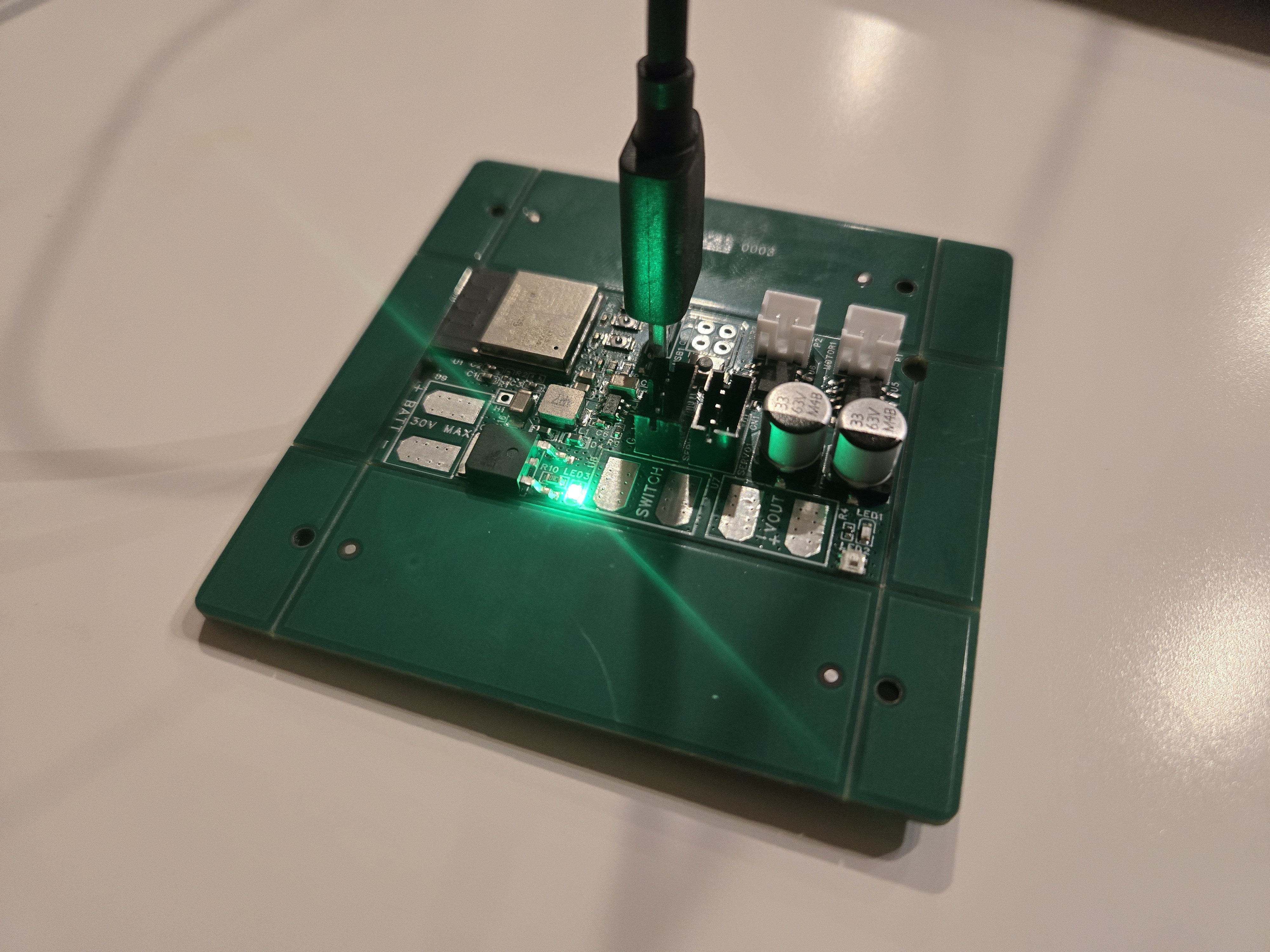
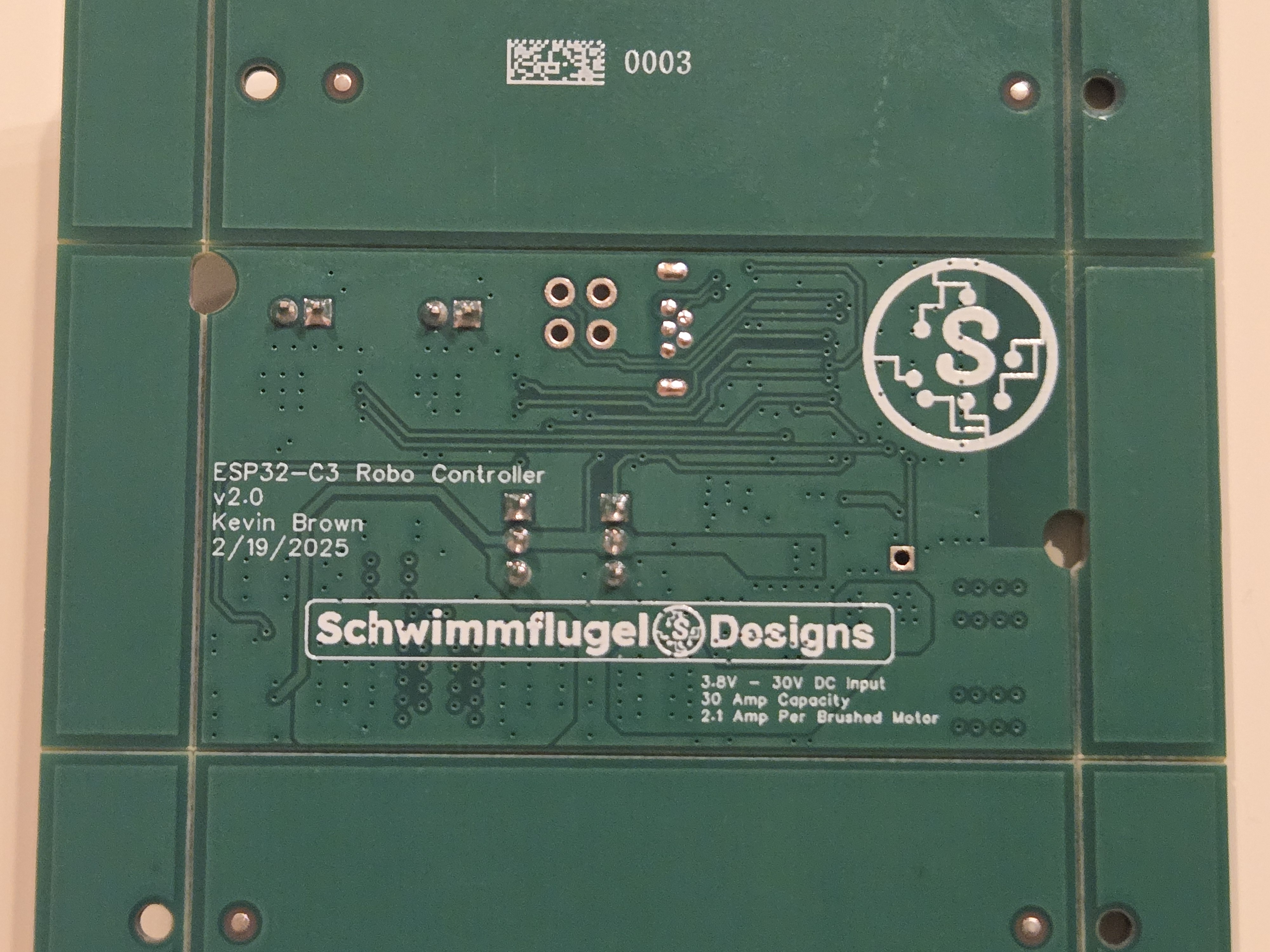
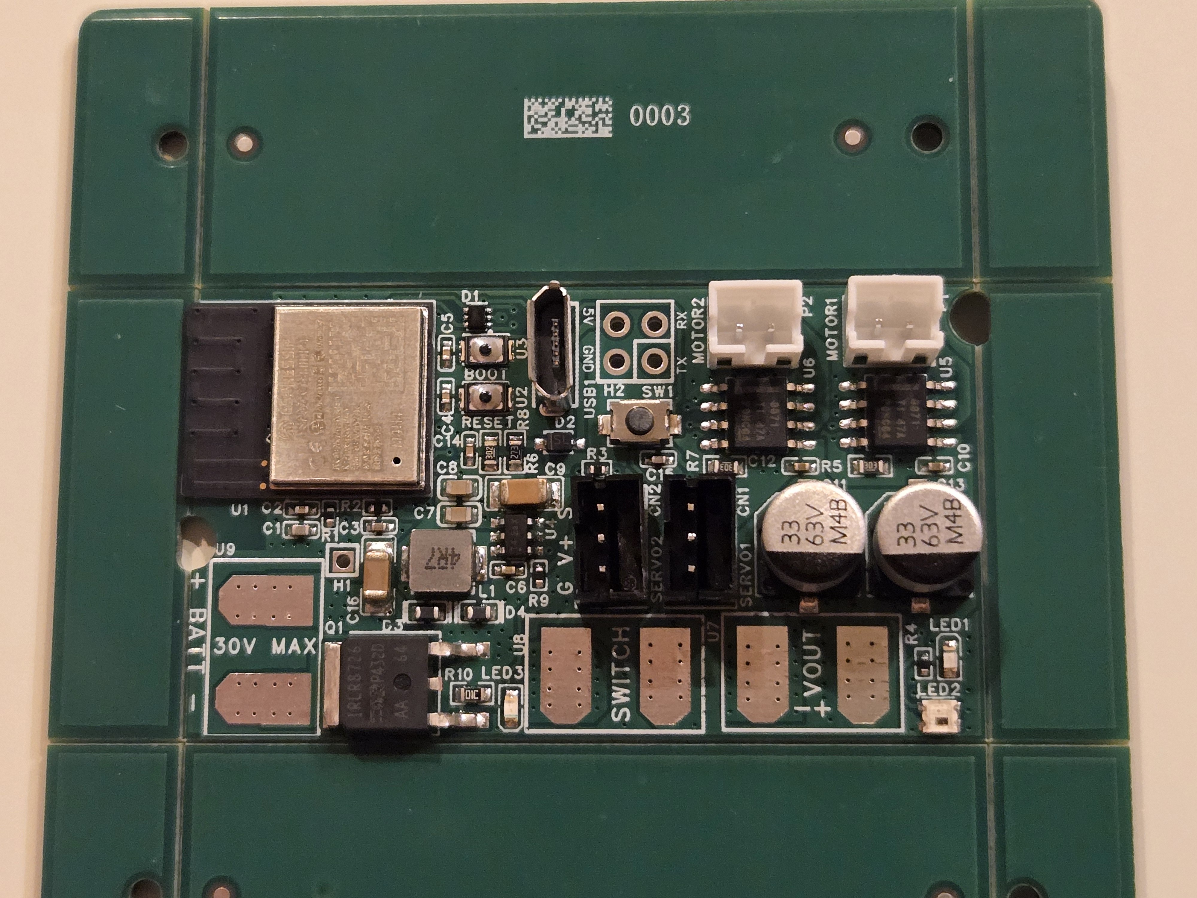
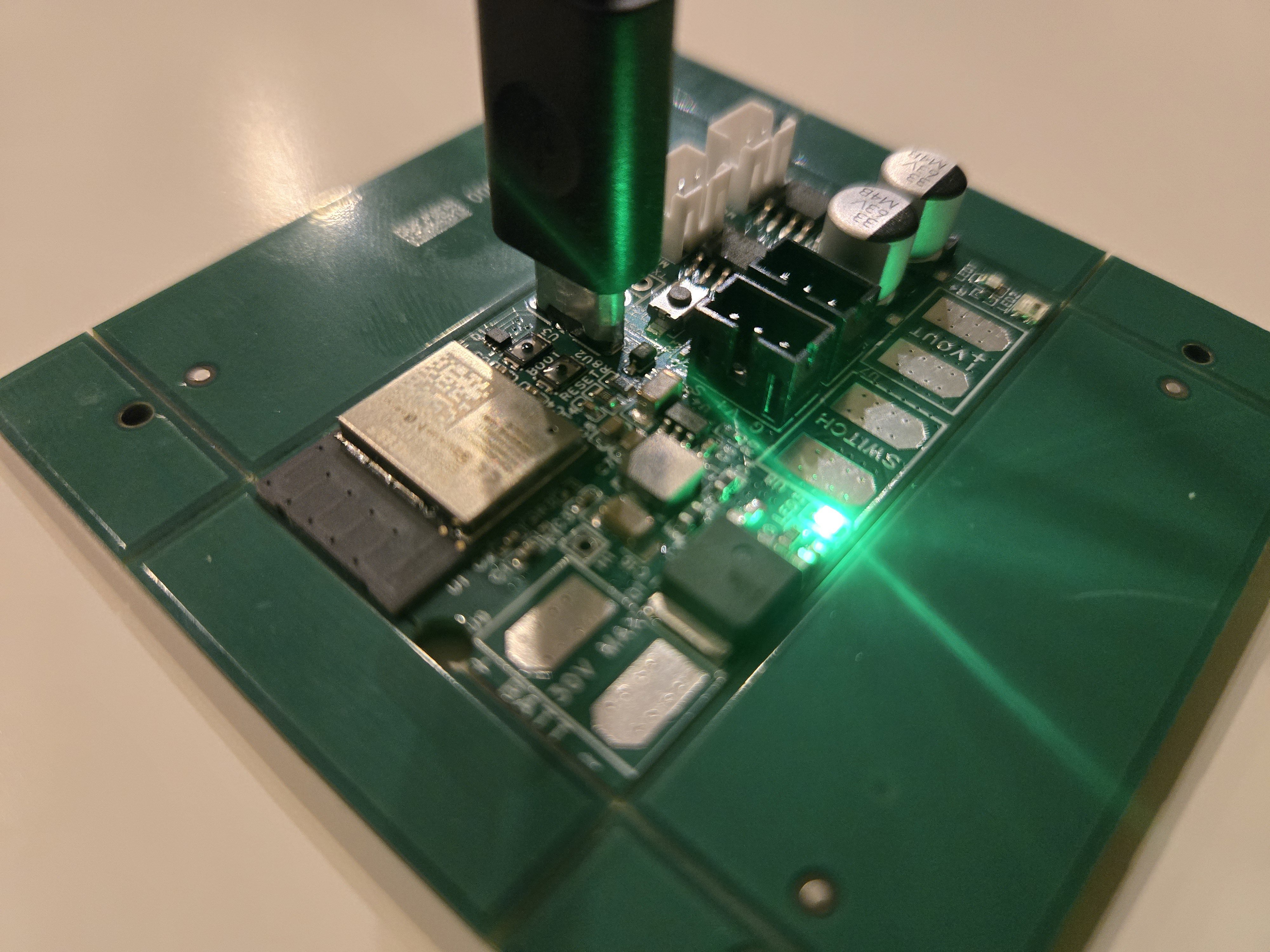
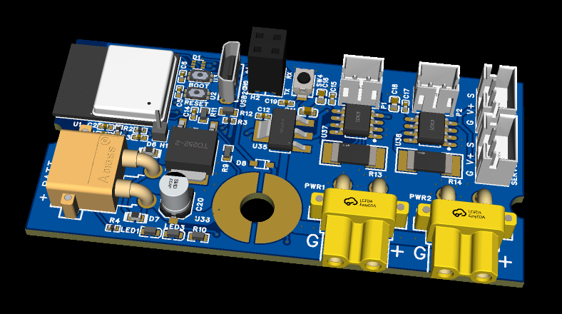
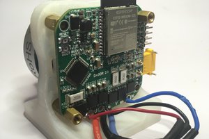
ESP32 Combat Robot Controller
A versatile ESP32-C3-based control board for combat robots, featuring BLE gamepad support for seamless wireless control.
 Schwimmflugel
Become a Hackaday.io member
Already have an account? Log in.
Just one more thing
To make the experience fit your profile, pick a username and tell us what interests you.
Pick an awesome username
hackaday.io/
Your profile's URL: hackaday.io/username. Max 25 alphanumeric characters.
Pick a few interests
Projects that share your interests
People that share your interests

 David Gonzalez
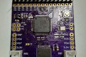
 Ben Lim
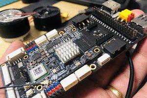
 GEEKROS