 Arnov Sharma
For the game, we created the traditional Snake game from scratch, with a simple Snake entity that can be controlled by four directional buttons. Randomly, a RED Dot appears on the matrix panel, and we may guide the snake to eat this random red dot using the Directional buttons. In the top right corner, we've also added a score marker, which keeps track of how many red dots our snake has consumed.
Furthermore, the game ends when a snake bites its own body.
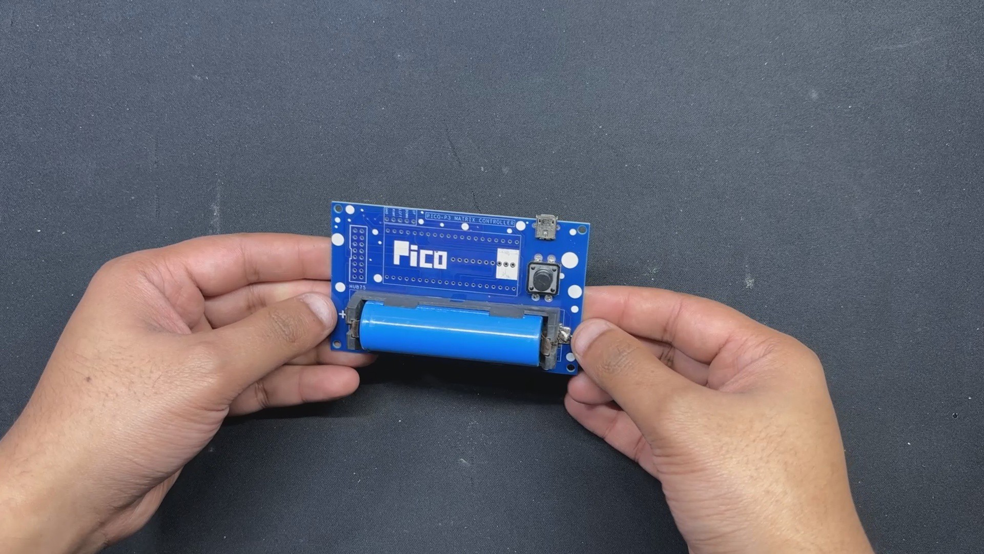
This console has an onboard power source, which is a single 3.7V 2600mAh lithium ion cell that powers the device, making it a portable game system that we can take anywhere and start playing.
64x32 RGB Matrix
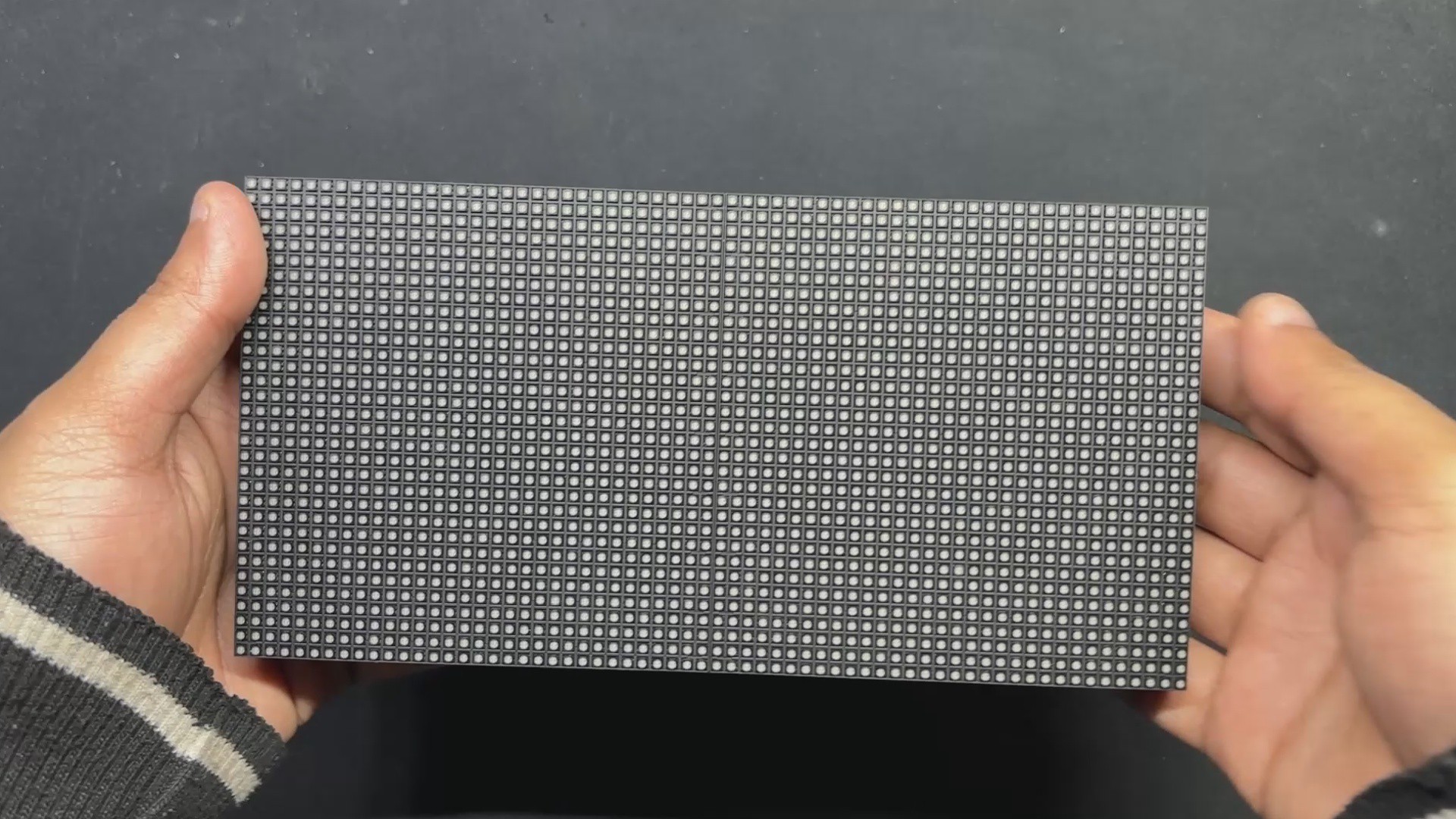

We are using the 64x32 RGB matrix panel, which creates vivid text, graphics, and animations by arranging 2048 RGB LEDs in a 64 by 32 grid.
You can click the link below to read my brief introduction to this matrix panel.
https://www.hackster.io/Arnov_Sharma_makes/64x32-matrix-panel-setup-with-pico-2-25a3c3
The HUB75 interface, which uses a number of control pins, including RGB, address, clock, data latch, and output enable pins, is used to operate this panel.
The row-column scanning technique is made possible by the HUB75 link, which shifts a row of pixel data into a shift register. A demultiplexer is then used to determine which rows should be displayed. RGB channels, addressing pins A, B, C, and D, a clock signal (CLK), a latch signal (LAT), and an output enable (OE) pin are all included in the HUB75 connector.
We can also link several panels in pairs to create a chain by using the provided IN and OUT connections. Making sure the control solution (PICO 2) we are using can manage the additional data load of two or more displays is one of the difficulties of connecting multiple panels.
This matrix was produced by Waveshare, and more thorough details on the Matrix board may be found at the wiki page below:
https://www.waveshare.com/wiki/RGB-Matrix-P3-64x32
As for sourcing this matrix panel, we got it from the PCBWAY GIFTSHOP.
Console Design


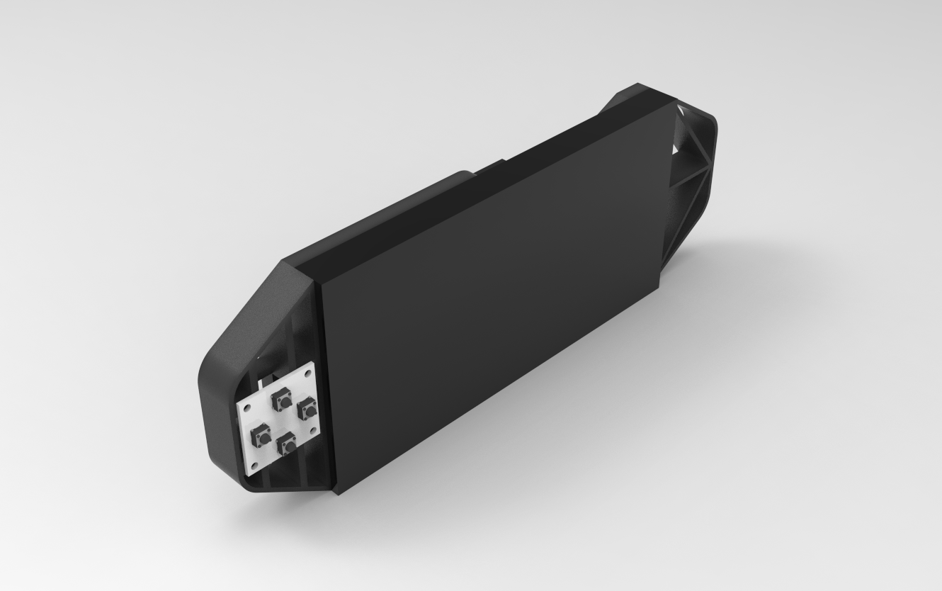
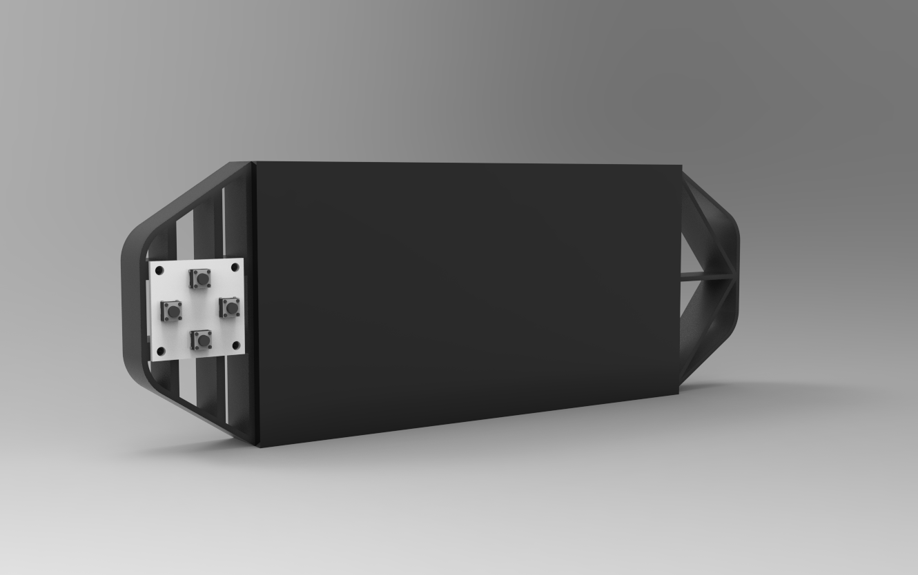

The first stage in this project was to build a 3D model of the console, which has two handgrip-like components installed on the back side of the matrix. We then created a model of the special button board on one side.
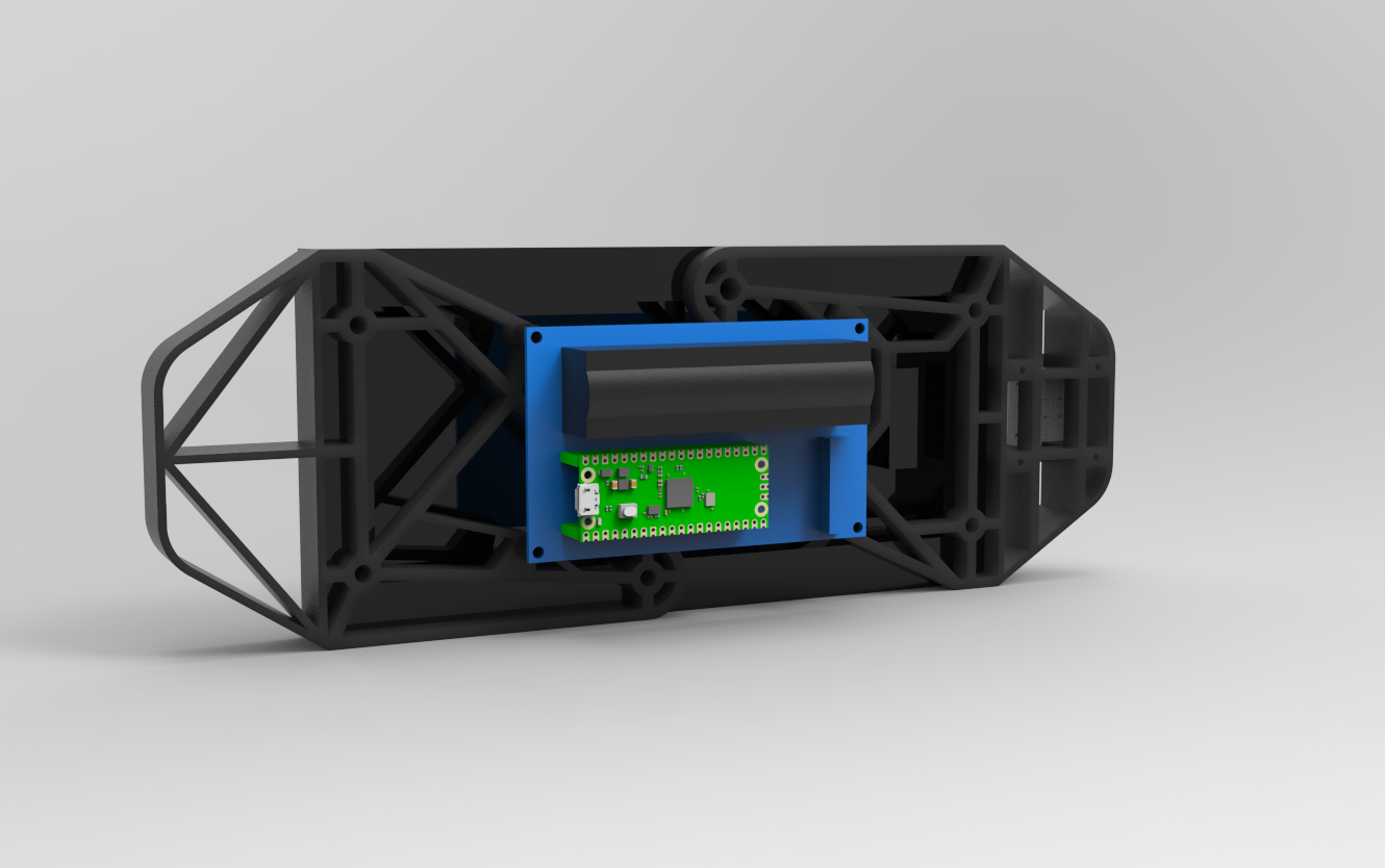
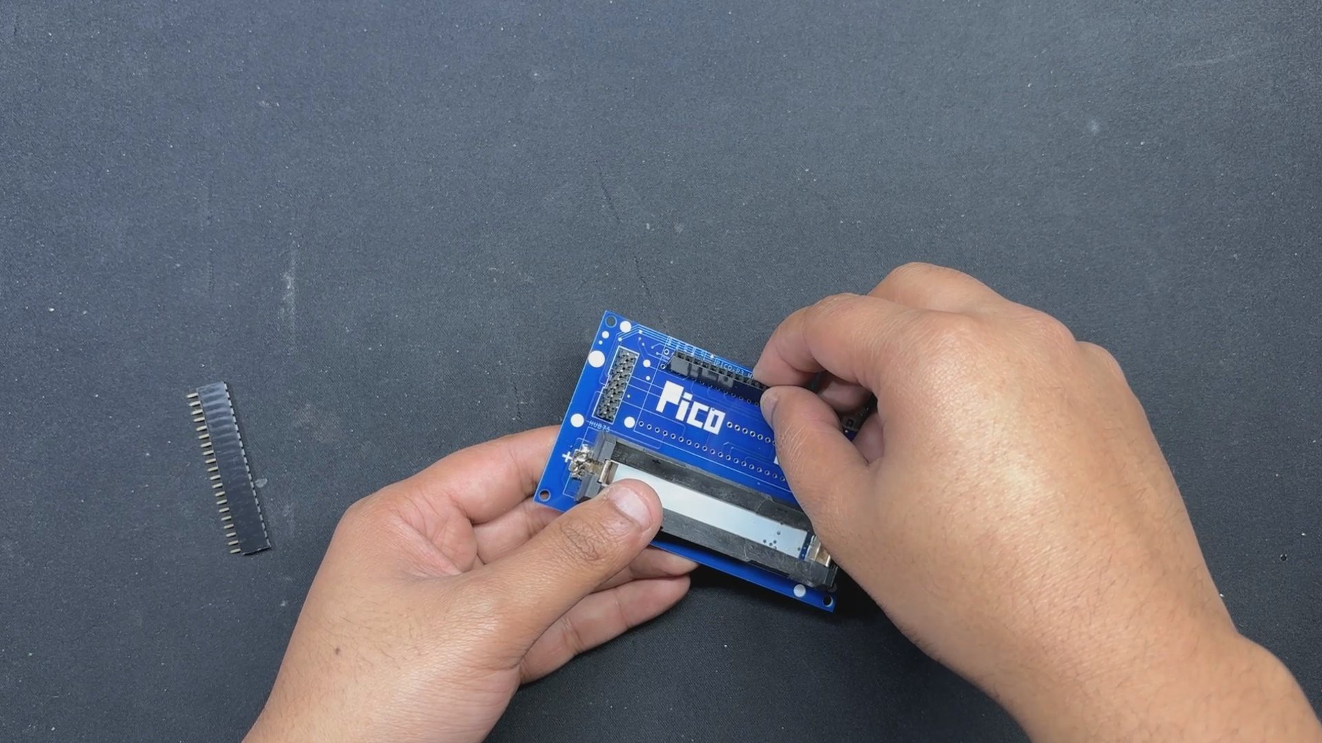
The PICO Driver circuit, which is fastened to the Handgrip frame with four spacers, is positioned on the back side of the device.
Using three M3 inserts that are already on the matrix, the two Handgrip frame components are mounted from the back of the matrix panel. Each handgrip has three mounting holes that we added so that M3 bolts can be used to attach the handgrip to the matrix.
Four M2 screws are used to secure the button board to one side of the console.
Once the model was complete, we exported the mesh files for the left and right handgrips and four spacers, then used a 0.6mm nozzle to 3D print them in black PLA.
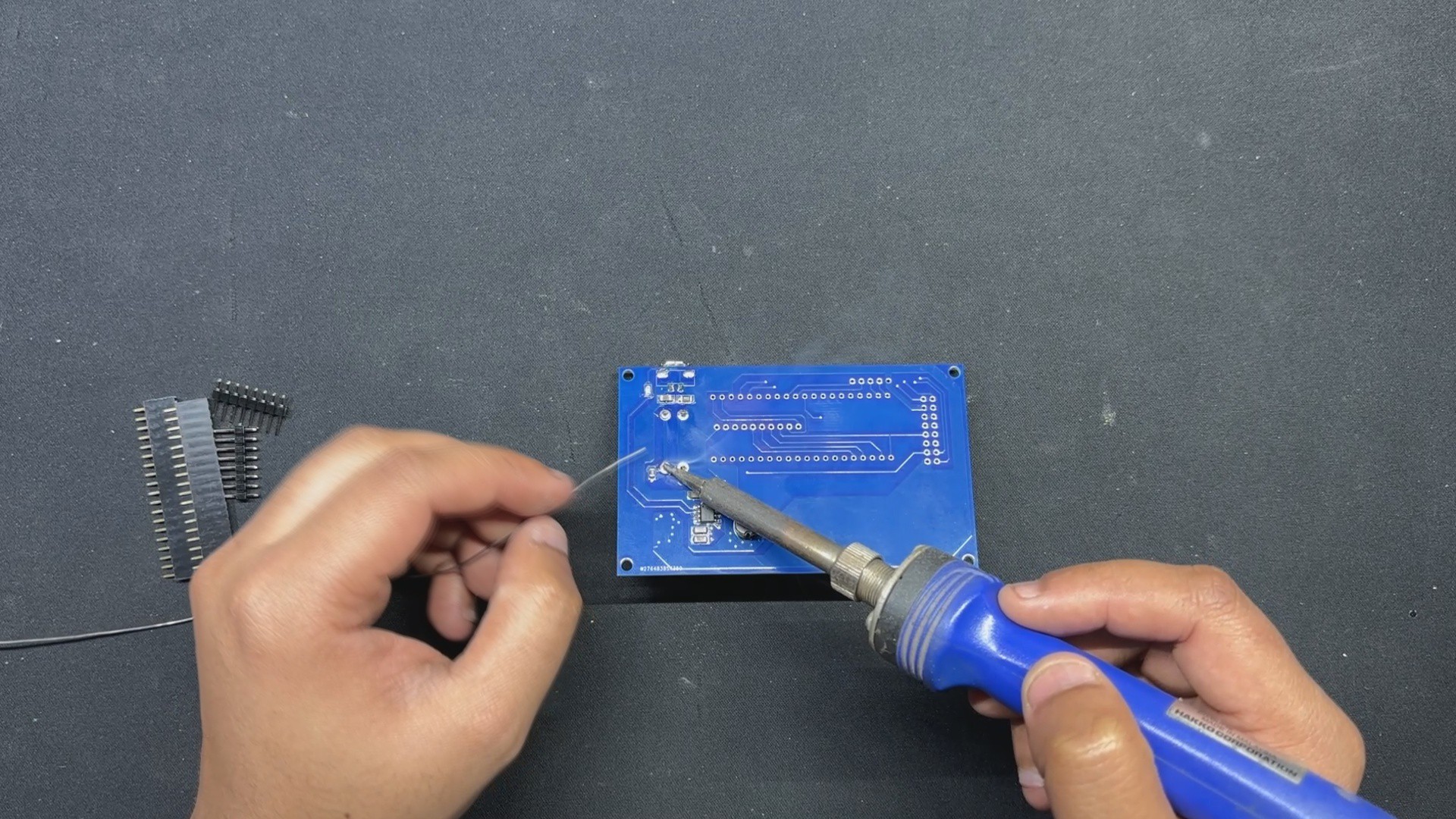
PCB Design: PICO Driver

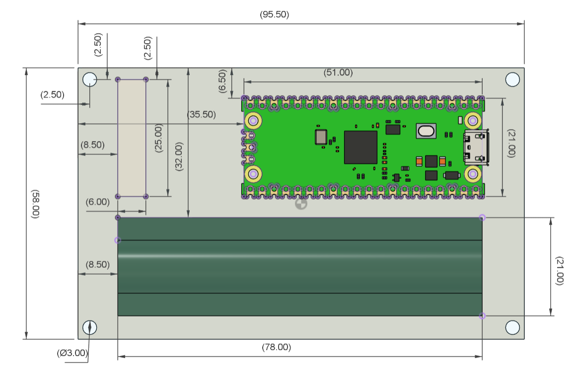
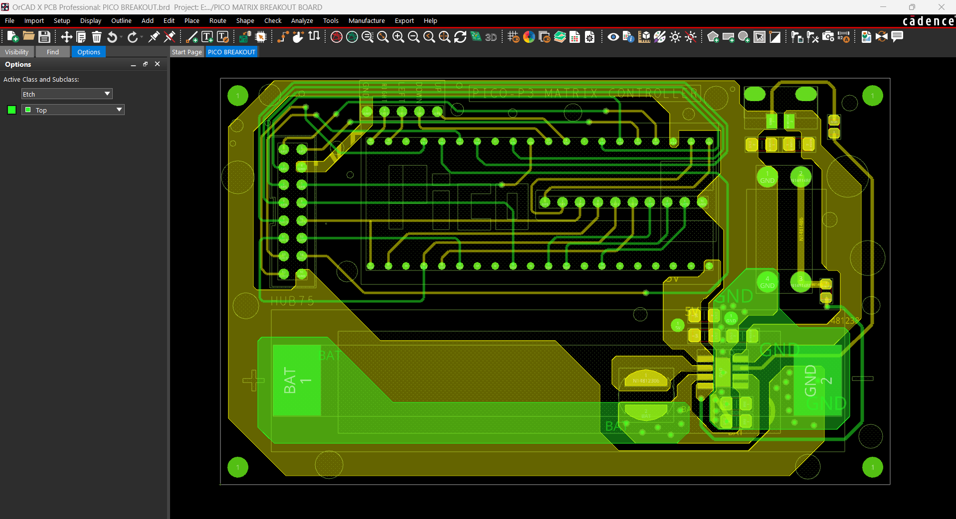

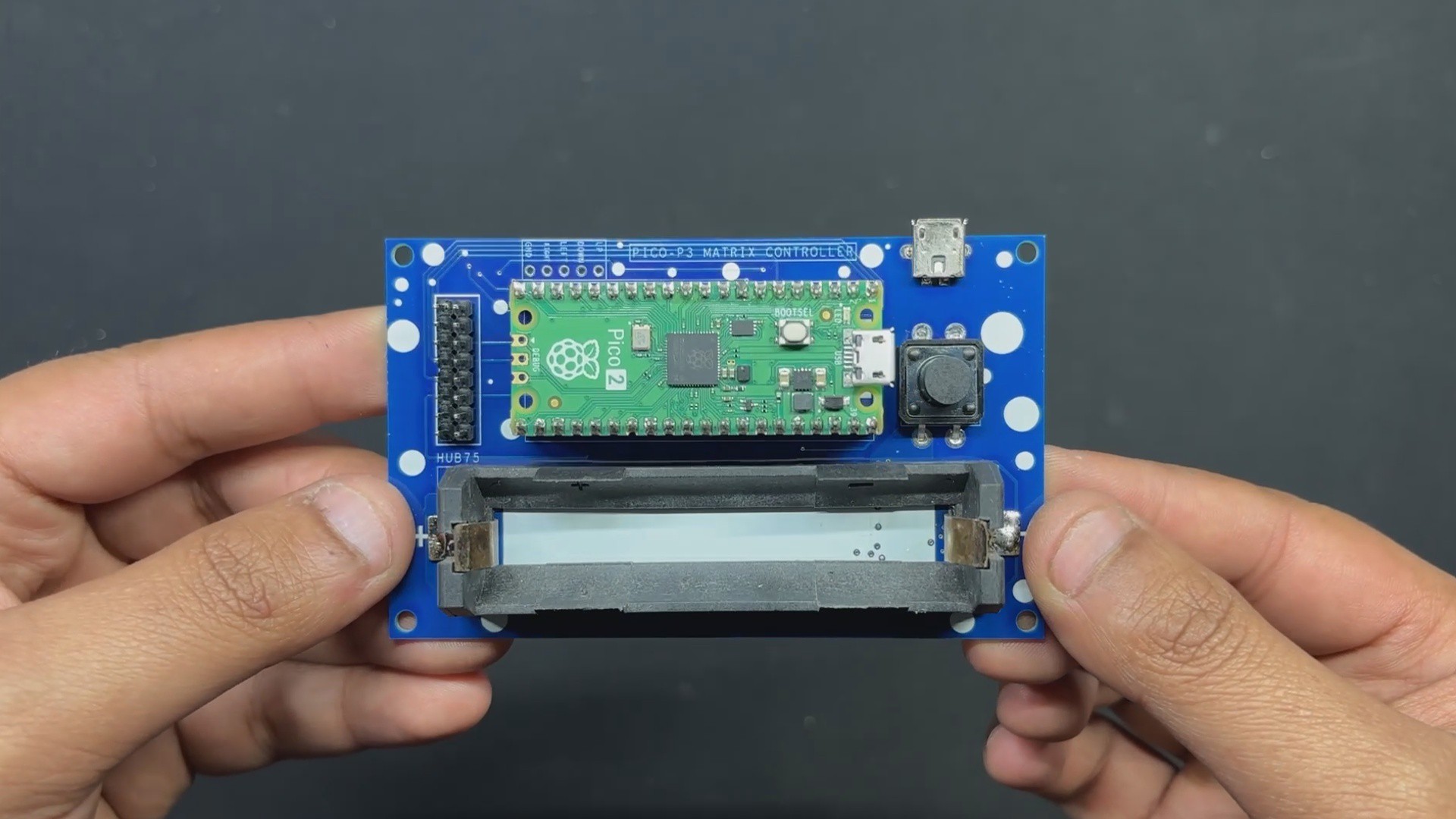
Using our PCB Cad software, we first create the schematic for the PICO Driver Board design. In order to connect the Raspberry Pi PICO 2 to the Matrix's HUB75 connector, our setup consists of of a CON 16 connector.
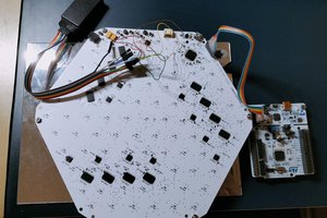
We connected the matrix's HUB75 pins (CON 16) to the PICO's GPIO pins in the following order: A to GPIO19, B to GPIO16, C to GPIO18, D to GPIO20, E to GPIO22, CLK to GPIO11, LAT/STB to GPIO12, OE to GPIO13, R1 to GPIO2, G1 to GPIO3, B1 to GPIO4, R2 to GPIO5, G2 to GPIO8, B2 to GPIO9.
We added a CON5 connector for buttons, and its four pins are connected to PICO's GPIO6, GPIO7, GPIO14, and GPIO15. GND is attached to CON5's fifth pin. Each GPIO will be pulled to GND by the button board that connects to this CON5, and PICO can detect this as a button press.
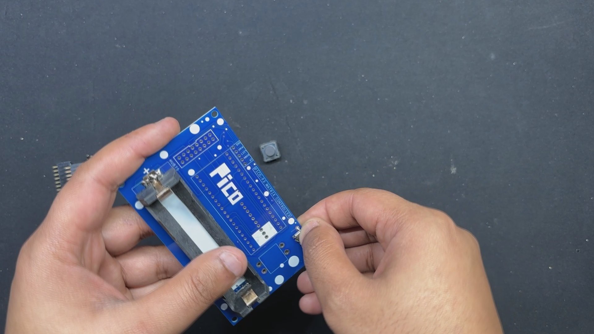
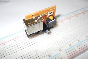
We also incorporated a power management IC, the IP5306, a fully integrated multi-function power management SoC, to power the entire setup.
It can provide steady 5V 2.1A using 3.7V...
Read more »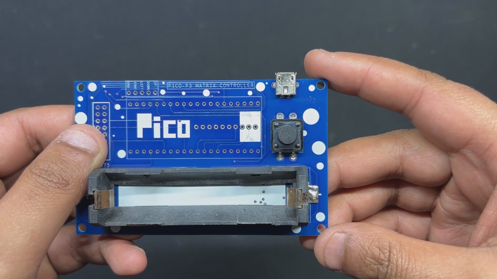


 danjovic
 Gregory Meltzer
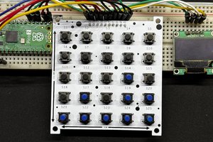
 Abel Rodriguez