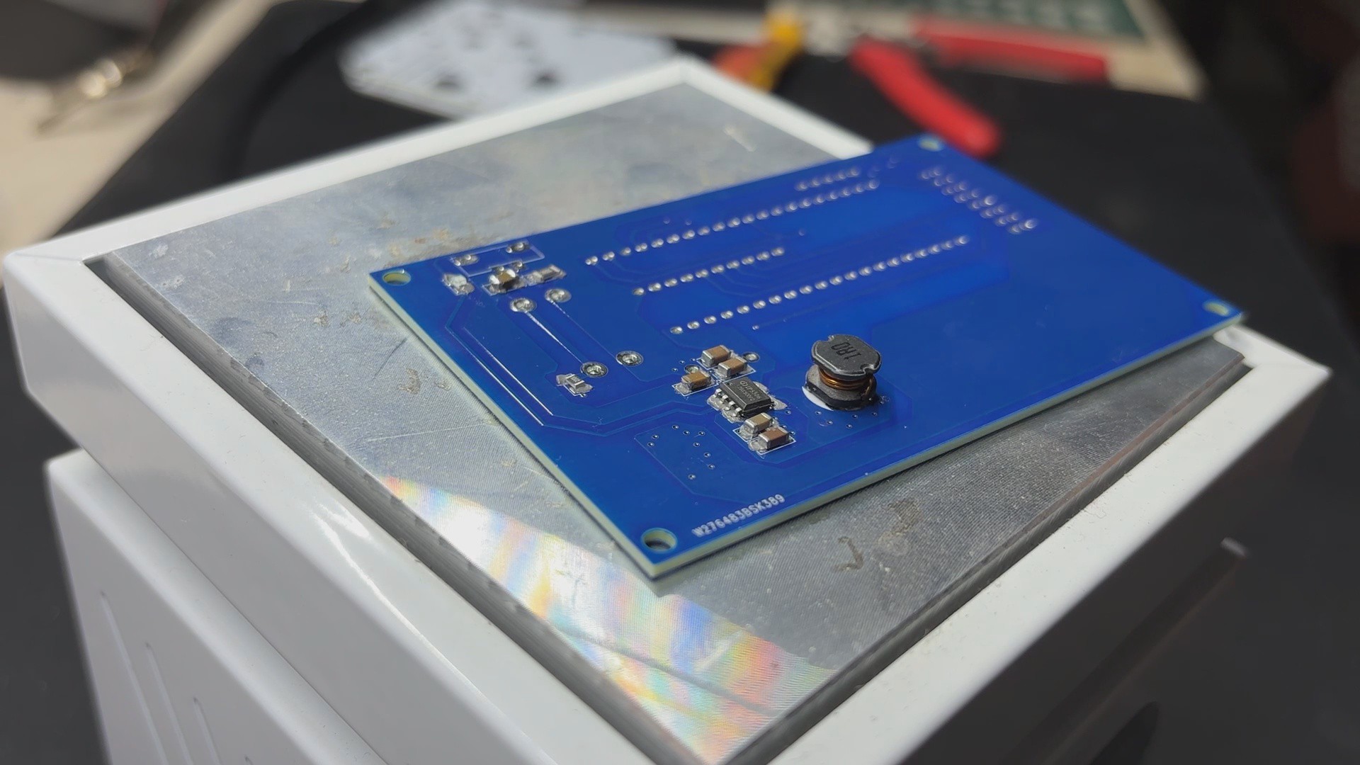
Using a solderpaste dispencing needle, we apply solderpaste—in this case, 63/37 Sn/Pb solderpaste—on each SMD component PAD to begin the PICO Driver assembly process.
Next, we use an ESD Tweeser to select and position each SMD component on the PCB.
Following component placement, the circuit is raised and set on the reflow hotplate, which raises the PCB's temperature from below to the melting point of solder paste. Solder paste melts and all SMD components are secure in place when the PCB hits a temperature of 190° C.
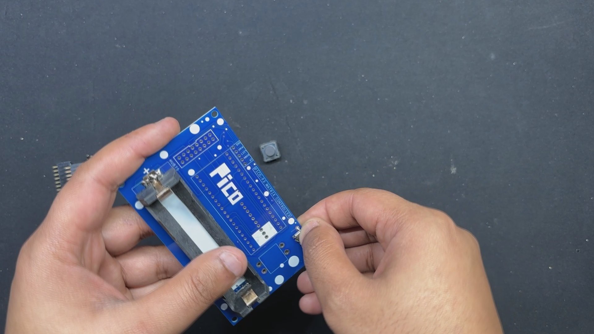
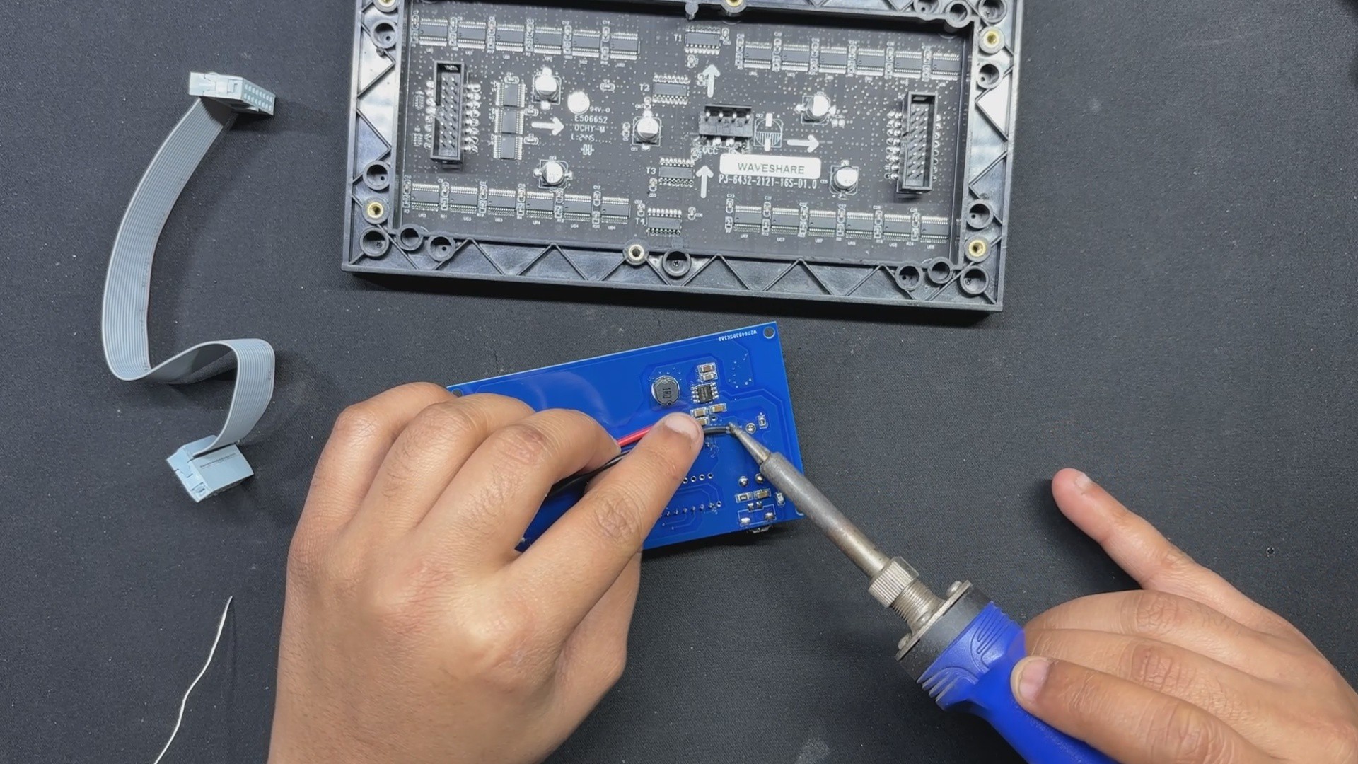
Following the reflow procedure, we flip the board over and use a soldering iron to position the 18650 Holder.
After the USB Micro port and Push Switch have been installed, we flip the board over and solder both of their pads.
2
Testing the Power Section
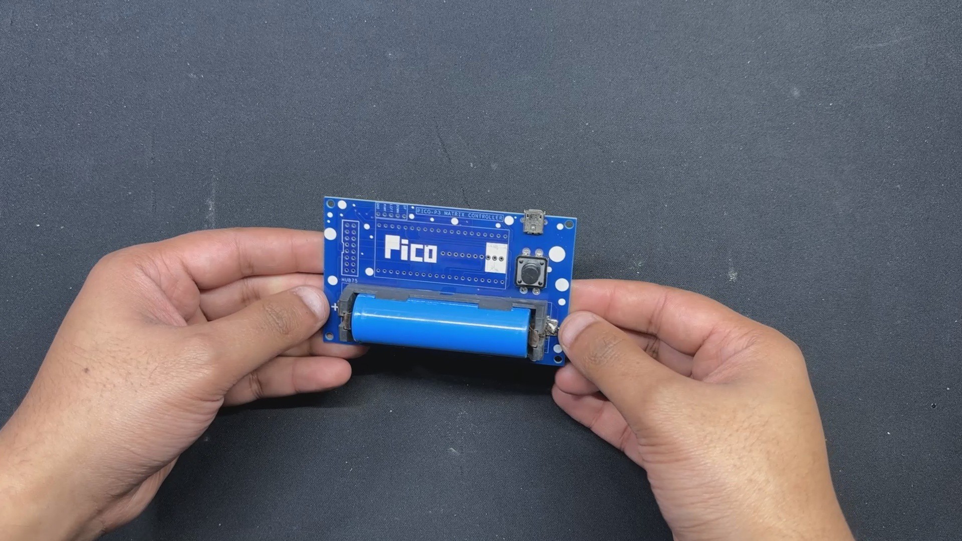
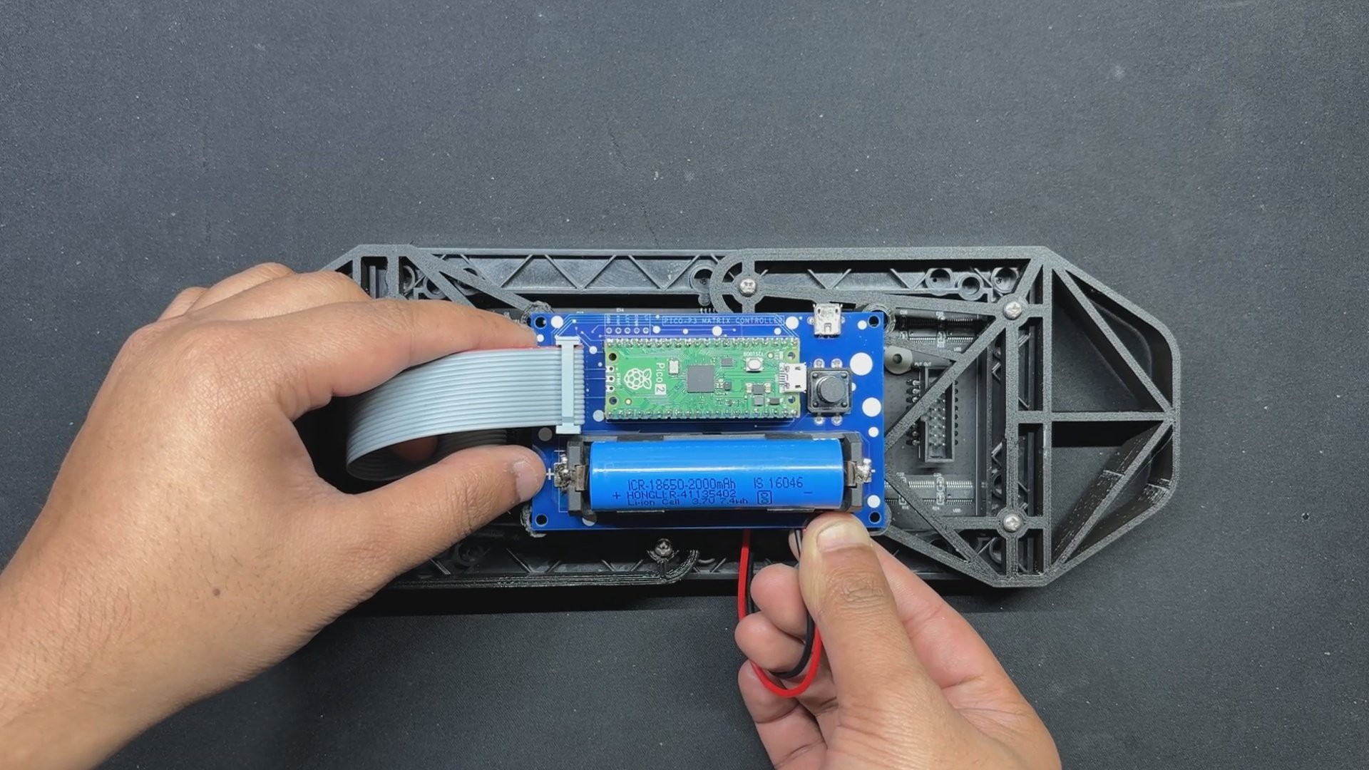
We stop our assembly process and verify the power module circuits by placing the 18650 3.7V 2600mAh lithium cell in its cell holder in the correct polarity before proceeding with the PICO DRIVER assembly process.
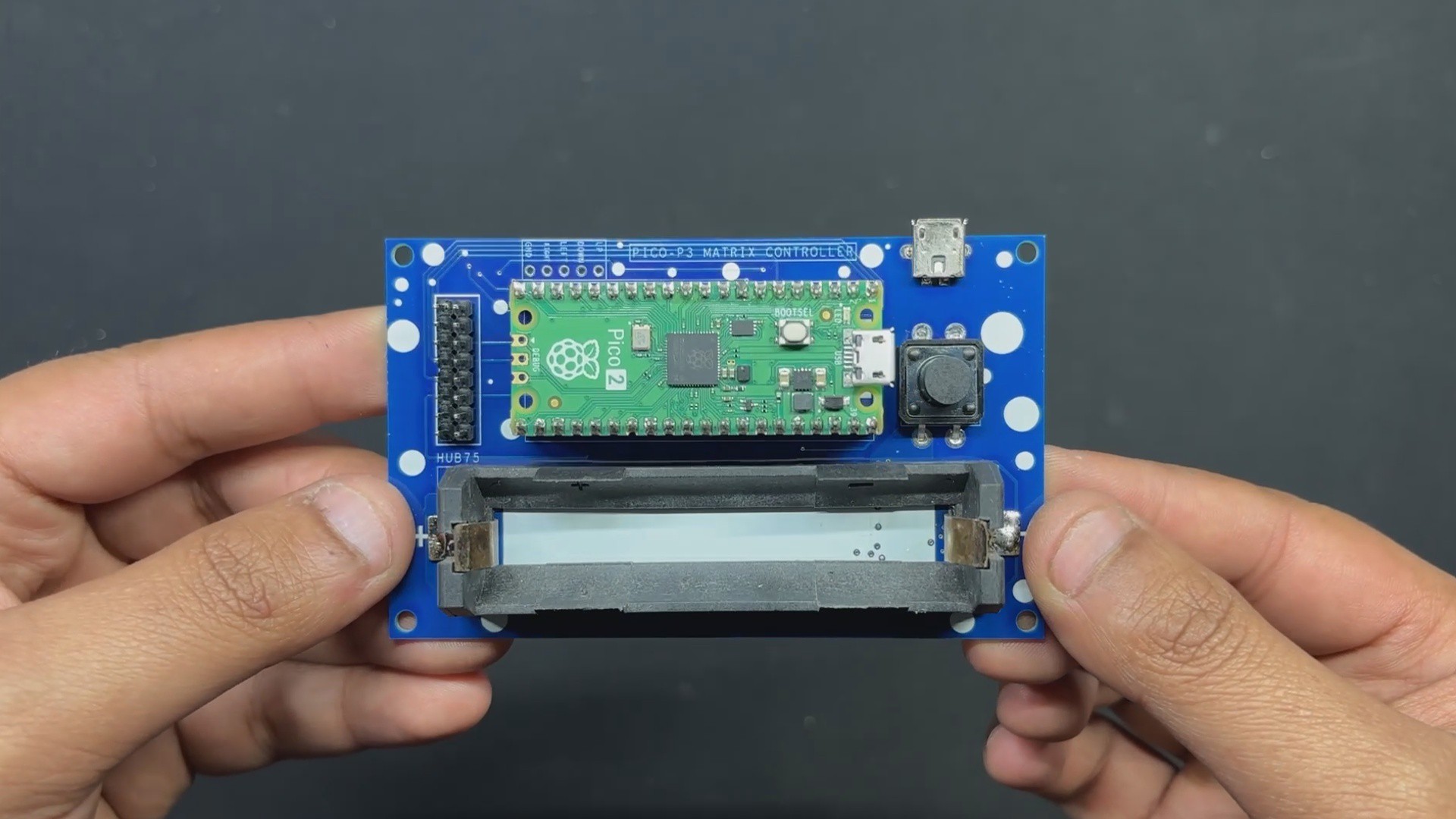
The device will then turn on when we press the push button. We use our multimeter to measure the device's output voltage, which should be 5V. We may now add PICO 2 to the PCB and start the assembly process.
3
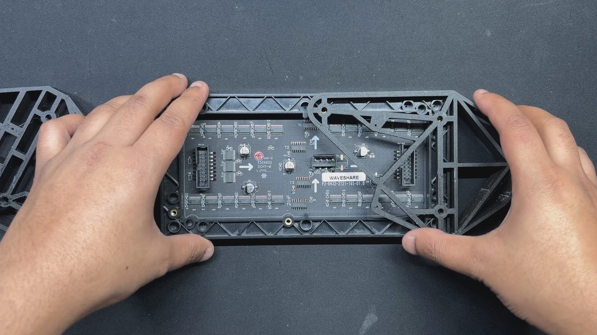
PCB ASSEMBLY: PICO DRIVER (Rest of the Assembly)
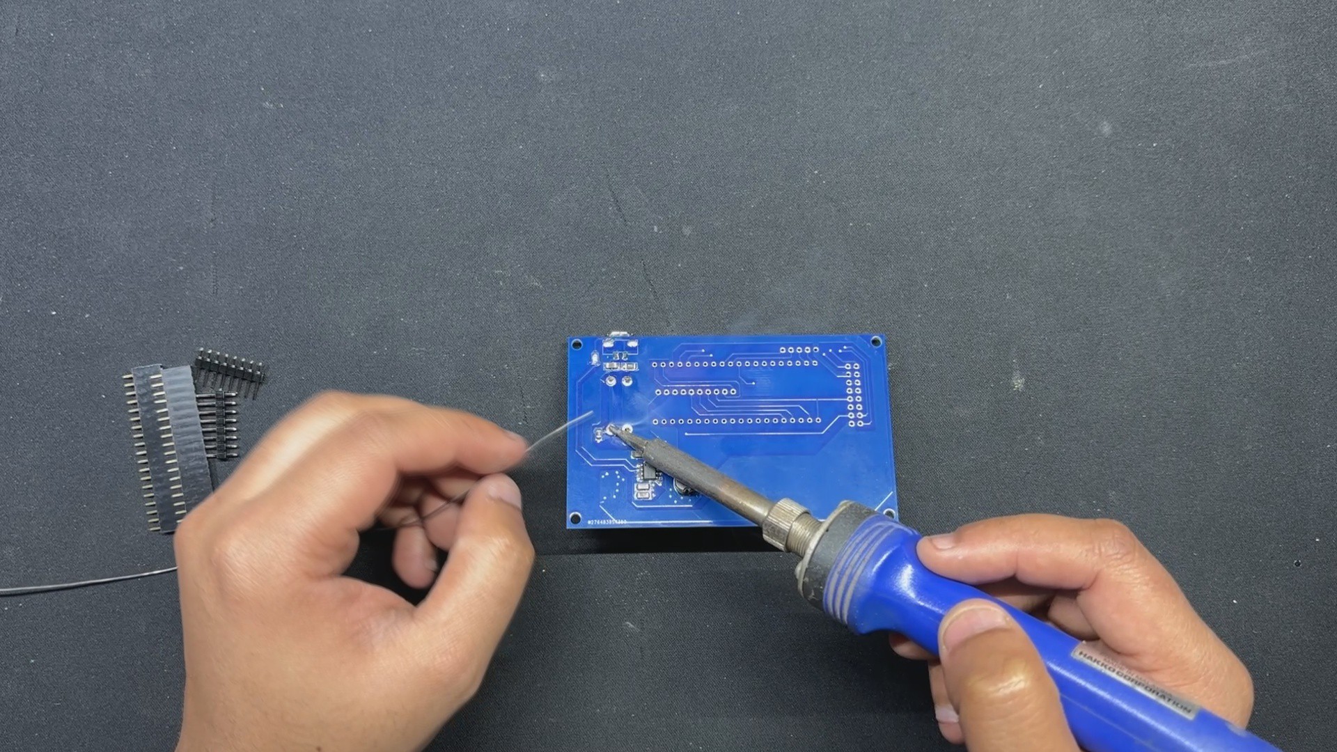
After positioning two female CON 20 header pins on the PICO 2 footprint and two male CON 8 header pins on the HUB75 connector footprint, we flip the board over and use a soldering iron to solder their pads.
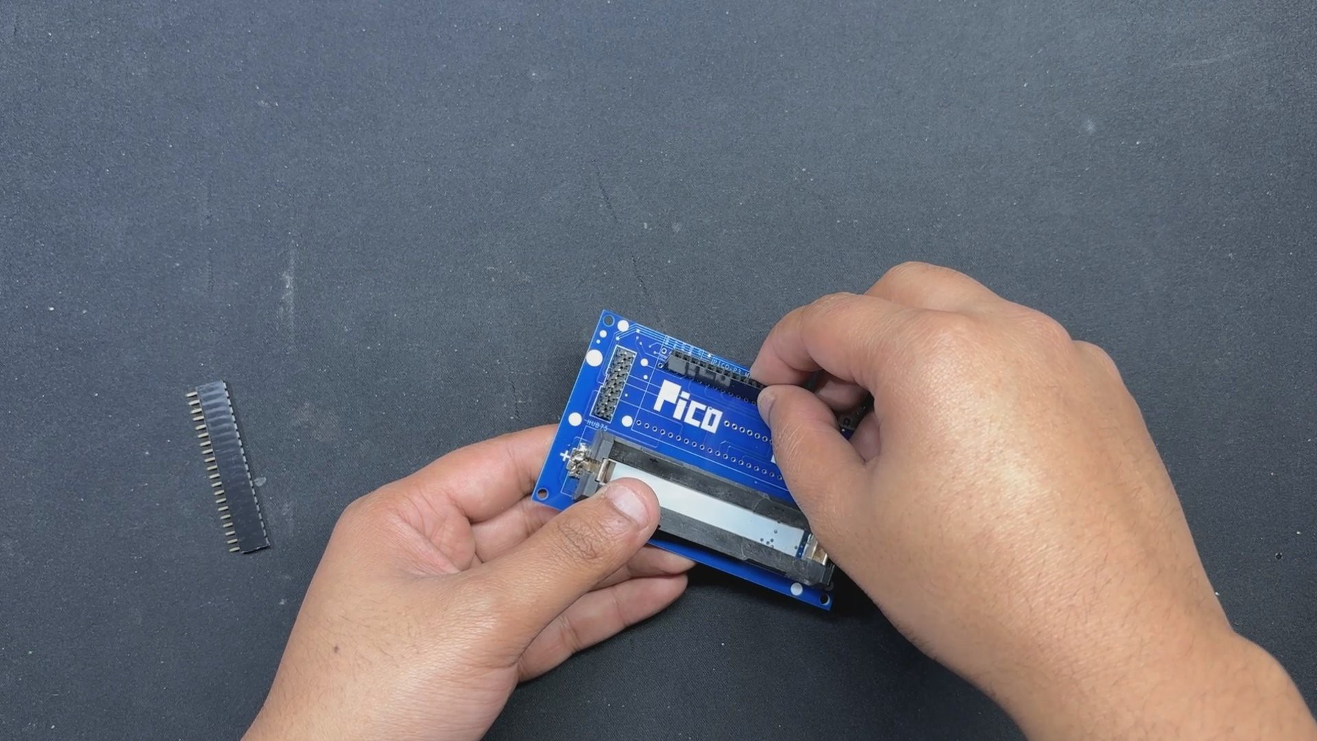
Finally, we reinstalled the lithium cell in its cell holder and positioned the Raspberry Pi PICO over the CON 20 header pins.
The PICO DRIVER Assembly is completed.
4
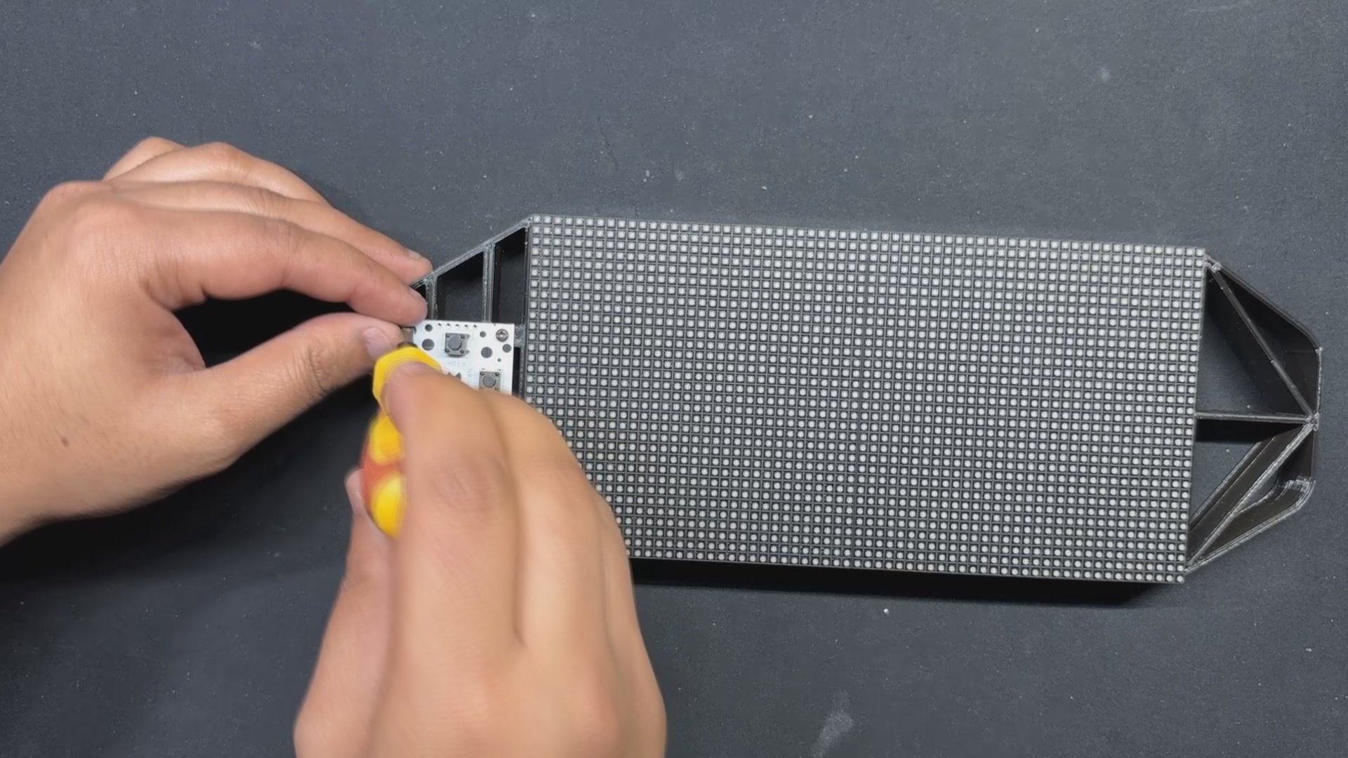
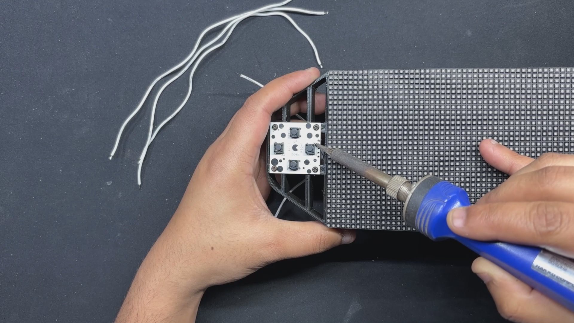
PCB ASSEMBLY: BUTTON BOARD
In order to begin the button board assembly process, we first position the push buttons from the top side of the board, and then we solder their pads from the bottom side.
5
PICO DRIVER and MATRIX ASSEMBLY
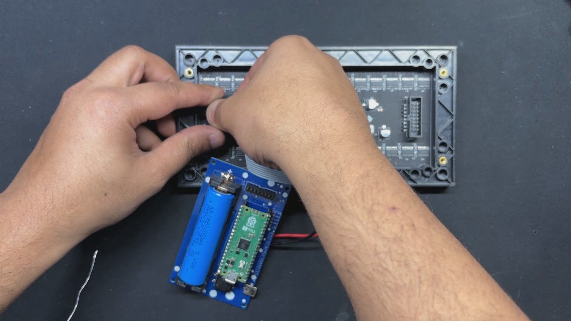
Using the wire harness that was included with the Matrix Kit, we first connect the PICO driver and Matrix. We soldered the positive wire of the wire harness to the 5V output of the PICO DRIVER and the negative wire to the GND of the PICO Driver.
Next, we attach the female wire harness connector to the matrix's male connector.
The HUB75 wire harness is then used to connect the matrix and PICO driver GPIOs. It is plugged into the matrix connector first, and then its other end is connected to the PICO driver.
6
TEST SKETCH: GAME OF LIFE
We connected the Mattrix and PICO DRIVE first, then flashed the PICO using our previously converted Game of Life code that we had taken from an example sketch of the FastLED library to see if our configuration worked.
The remarkable cellular automaton known as the "Game of Life" was developed in 1970 by British mathematician John Horton Conway. Since it is a zero-player game, no extra input is required; rather, the game's progression is determined by its initial state.
The game will start with a random configuration and restart with a new random configuration after it halts and yes this setup is Turing complete.
#include<Adafruit_Protomatter.h>// Pin definitions#define R1 2#define G1 3#define B1 4#define R2 5#define G2 8#define B2 9#define A 10#define B 16#define C 18#define D 20#define CLK 11#define LAT 12#define OE 13#define WIDTH 64#define HEIGHT 32uint8_t rgbPins[] = { R1, G1, B1, R2, G2, B2 };
uint8_t addrPins[] = { A, B, C, D };
Adafruit_Protomatter matrix(WIDTH, HEIGHT, 1, rgbPins, 4, addrPins, CLK, LAT, OE, false);
bool grid[WIDTH][HEIGHT];
bool newGrid[WIDTH][HEIGHT];
voidsetup(){
matrix.begin();
randomSeed(analogRead(0));
// Initialize grid with random valuesfor(int x = 0; x < WIDTH; x++) {
for(int y = 0; y < HEIGHT; y++) {
grid[x][y] = random(2);
}
}
}
voidloop(){
matrix.fillScreen(0);
// Update grid based on Game of Life rulesfor(int x = 0; x < WIDTH; x++) {
for(int y = 0; y < HEIGHT; y++) {
int aliveNeighbors = countAliveNeighbors(x, y);
if(grid[x][y]) {
// Any live cell with two or three live neighbors survives.if(aliveNeighbors < 2 || aliveNeighbors > 3) {
newGrid[x][y] = false;
} else {
newGrid[x][y] = true;
}
} else {
// Any dead cell with three live neighbors becomes a live cell.if(aliveNeighbors == 3) {
newGrid[x][y] = true;
} else {
newGrid[x][y] = false;
}
}
if(newGrid[x][y]) {
matrix.drawPixel(x, y, matrix.color565(255, 255, 255)); // White color
}
}
}
// Copy newGrid to gridmemcpy(grid, newGrid, sizeof(grid));
matrix.show();
delay(100); // Adjust the delay for speed control// Check if the grid is stable or emptyif(isGridStableOrEmpty()) {
resetGrid();
}
}
intcountAliveNeighbors(int x, int y){
int aliveNeighbors = 0;
for(int dx = -1; dx <= 1; dx++) {
for(int dy = -1; dy <= 1; dy++) {
if(dx == 0 && dy == 0) continue;
int nx = (x + dx + WIDTH) % WIDTH;
int ny = (y + dy + HEIGHT) % HEIGHT;
if(grid[nx][ny]) {
aliveNeighbors++;
}
}
}
return aliveNeighbors;
}
We are using the <em><strong>Adafruit_Protomatte</strong></em>r library here which you need to install on your Arduino IDE before using this code.
7
FRAME & MATRIX ASSEMBLY
By aligning the mounting holes of the two 3D-printed handgrip frames with those of the matrix, we can now attach them to the back of the matrix. Six M3 bolts are then used to connect the frame and matrix together. We can easily connect the frame and matrix with an M3 bolt thanks to the M3 brass inserts that have been added to the back of the matrix.
8
BUTTON BOARD—FRAME ASSEMBLY
The button board is then positioned from the front of the console, and four M2 screws are used to secure it in place.
9
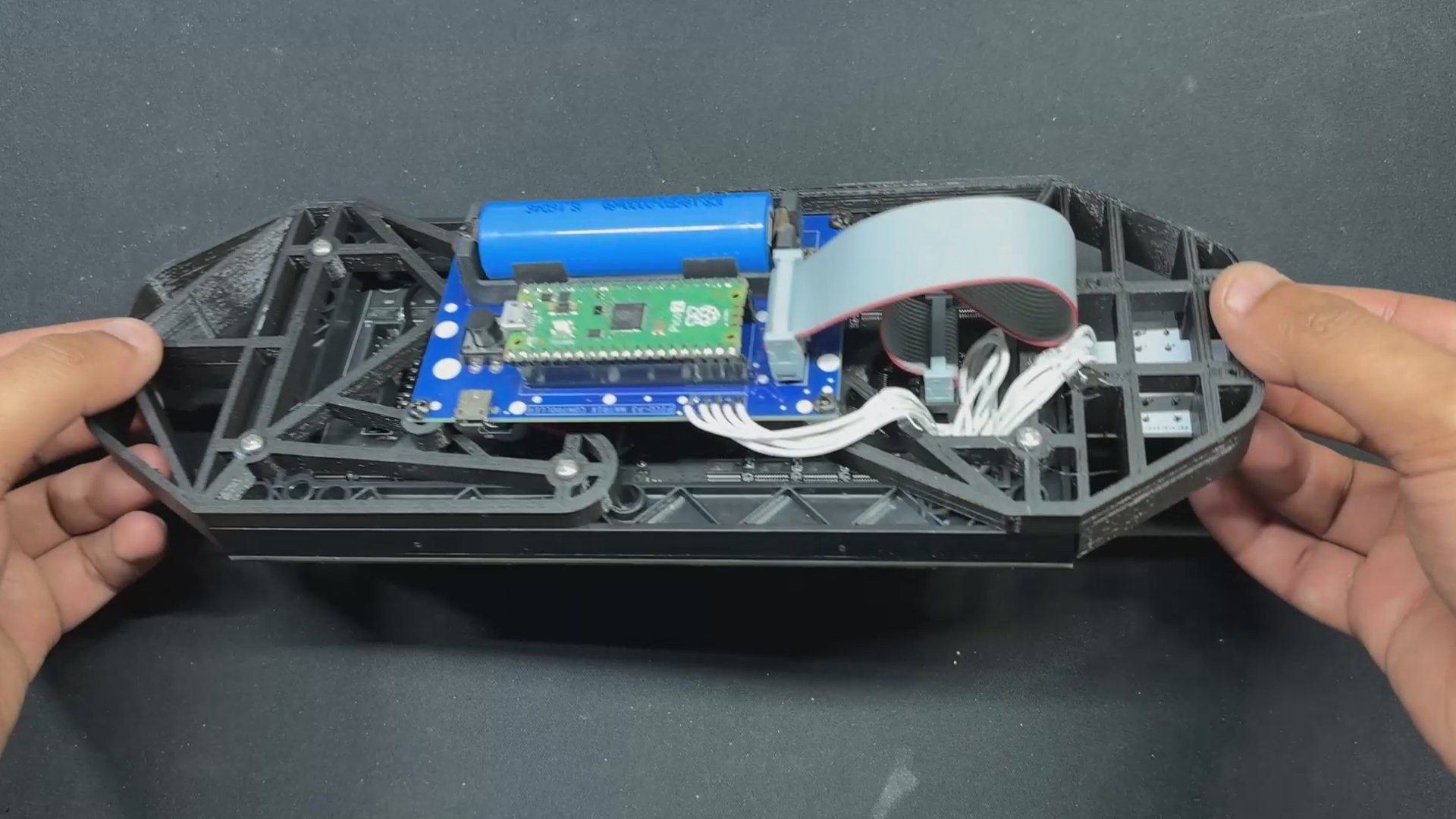
PICO DRIVER & FRAME ASSEMBLY
Now, we use four 3D-printed spacers to position the PICO DRIVER on the back side of the console over the 3D-printed frame.
We put the PICO driver over the four spacers that are placed over the mounting hole on the frame, and then use M3 screws to secure the PICO driver to the frame.
10
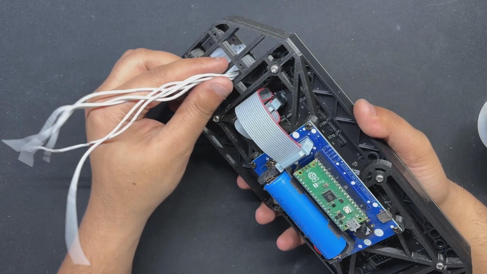
FINAL ASSEMBLY: BUTTON BOARD & PICO DRIVER WIRE CONNECTIONS
Wiring the DPAD Button PCB and PICO DRIVER board together is the final stage in the assembly process.
To accomplish this, we first add five connecting wires to the button board's CON5 port, and then we connect each wire to the PICO DRIVER in the correct pin order.
The button board's UP pin is connected to GPIO7, DOWN pin to GPIO6, LEFT pin to GPIO15, and RIGHT pin to GPIO14.
Once the wires between the PICO DRIVER and the button board are connected, we carefully tuck the extra wire length within the frame and secure it with a small bit of HOTGLUE.
 Arnov Sharma
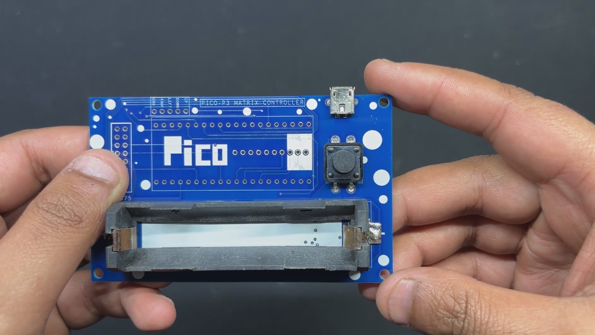


Discussions
Become a Hackaday.io Member
Create an account to leave a comment. Already have an account? Log In.