 maxandre.lena
-
1Materials needed
- Arduino UNO R3 board,
- 28BYJ-48 stepper motor,
- ULN 2003,
- 6 cables,
- wood glue,
- laser cutter,
- 3D printer,
Use the document clock v3.svg to cut out all the clock parts. Use the document clock base v3.stl to print the base of the clock. Print and cut out the parts.
-
2Motor assemblyUpload the following code to the Arduino:
#include <Stepper.h>
const int stepsPerRevolution = 2048; // Pas pour un tour complet
// Brochage adapté au 28BYJ-48
Stepper myStepper(stepsPerRevolution, 8, 10, 9, 11);void setup() { // Réglé pour 6 tours par minute myStepper.setSpeed(6);
}void loop() { // Faire tourner le moteur continuellement à 6 tours par minute myStepper.step(-1); // 1 pas à la fois, vitesse contrôlée par setSpeed()
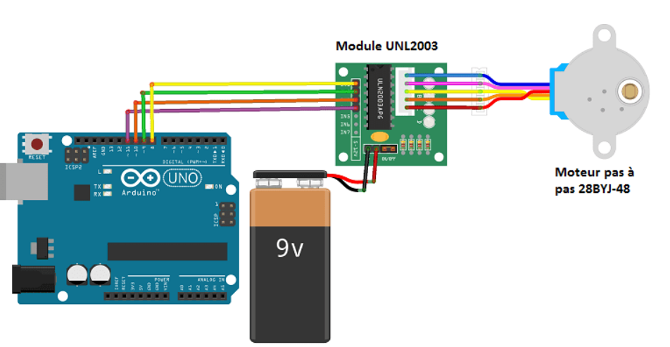
}The motor connections are made in the same way as shown in the photo image.png.
After preparing the parts, proceed with assembling the clock.
Gluing steps:
Glue together 2 10-tooth x 8 gears,
Glue together 6 10-tooth x 1 gears,
Glue together 2 20-tooth x 1 gears,
Glue together 2 40-tooth x 1 gears,Then glue, in succession, the 2 x 40-tooth gear, the 60-tooth gear, and finally the 2 x 20-tooth gear,
Glue the 6 x 10-tooth gear to the 60-tooth gear,
Glue together 2 x 10-tooth gears on either side of a 60-tooth gear,
Glue a 2 x 10-tooth gear to a 50-tooth gear,
Glue a 2 x 10-tooth gear to a 40-tooth gear,
Glue a 2 x 10-tooth gear to a 30-tooth gear,Glue the first hand to the 6 x 10-tooth gear, connected to the 60-tooth gear,
Glue the second hand to the 2 x 10-tooth gear, connected to the 2 x 20-tooth gear, connected to the 60-tooth gear, connected to the 2 x 40-tooth gear,
Glue the last hand to the 2 x 10-tooth gear, connected to the 60-tooth gear, connected to the 2 x 10-tooth gear.![]()
-
3Clock assembly:
1. Attach the motor at the hole in the base using glue. The rotating part of the motor must be visible and must not have any glue on it.
2. Glue a 2 x 10-tooth gear onto the rotating part of the motor.
For this section, we are only concerned with the thinnest pegs, 5 mm in diameter. The first peg is the one closest to the motor, the second peg is the one nearest to the first, and so on.
3. First peg: Place the 60-tooth gear with its 6 x 10-tooth gear,
4. Second peg: Place the 40-tooth gear with its 2 x 10-tooth gear (the 2 x 10-tooth gear should be closest to the base),
5. Third peg: Place the 50-tooth gear with its 2 x 10-tooth gear (the 2 x 10-tooth gear should be closest to the base),
6. Fourth peg: Place the 50-tooth gear,
7. Fifth peg: Place the 60-tooth gear with its 2 x 20-tooth and 2 x 40-tooth gears (the 2 x 40-tooth gear should be closest to the base),
8. Sixth peg: Place the 40-tooth gear,
9. Seventh peg: Place the 30-tooth gear with its 2 x 10-tooth gear (the 2 x 10-tooth gear should be closest to the base),
10. Eighth peg: Place the 30-tooth gear,
11. Ninth peg: Place the 60-tooth gear with its two 2 x 10-tooth gears (the clock hand is the part furthest from the base).For this part, we focus on the dials:
Glue the numbers (3, 6, 9, 12) onto the first dial:
12 is positioned at the very top, 3 on the far right of the circle, 6 at the bottom, and 9 on the far left.Glue the numbers (15, 30, 45, 60) onto the second and third dials:
60 is at the top, 15 on the right, 30 at the bottom, and 45 on the left.Glue the dial with (3, 6, 9, 12) onto the unused pegs located opposite the motor
(if the motor is placed at the top right, the relevant pegs are on the far left).Glue the remaining two dials onto the last unused pegs.
Plug your motor into a power source, you now have a working clock!
Discussions
Become a Hackaday.io Member
Create an account to leave a comment. Already have an account? Log In.