maxandre.lena
-
Conclusion
05/12/2025 at 16:37 • 0 commentsLet's take a look at what we need to improve. For a start, it would be best to find a better site for designing our gears. Secondly, having stronger, more robust axles would help the gears to hold better. Lastly, to prevent the gears from wobbling, we'd need to come up with a design that would hold them better - making them thicker would be the solution.
Finally, on the subject of aesthetics, we could imagine superimposing the hands to display the time.
-What we learned from this project..:
-the importance of time management
-the importance of dividing up tasks
-how 360° fusion works
-how a Servo Motor works
-how a LASER cutter worksThe challenges we faced:
-calculating the ratios between the gears, taking into account their radius so that they are not too large
-calculate the distances between the gears to prevent the mechanism from jamming
-superimpose the various gears and calculate their height
-fix the gears so that they rotate correctly in relation to each other -
Clock(April 22th)
05/12/2025 at 16:16 • 0 commentsWe have modified the motor code, and the gears attached to the motor now make 6 revolutions in 1 minute. So that the ratio between the gears is correct. Finally, our motor turns counterclockwise
#include <Stepper.h> const int stepsPerRevolution = 2048; // Steps for one full revolution // Pin configuration for the 28BYJ-48 motor Stepper myStepper(stepsPerRevolution, 8, 10, 9, 11); void setup() { // Set speed to 6 revolutions per minute myStepper.setSpeed(6); } void loop() { // Continuously rotate the motor at 6 RPM myStepper.step(-1); // One step at a time, speed controlled by setSpeed() } -
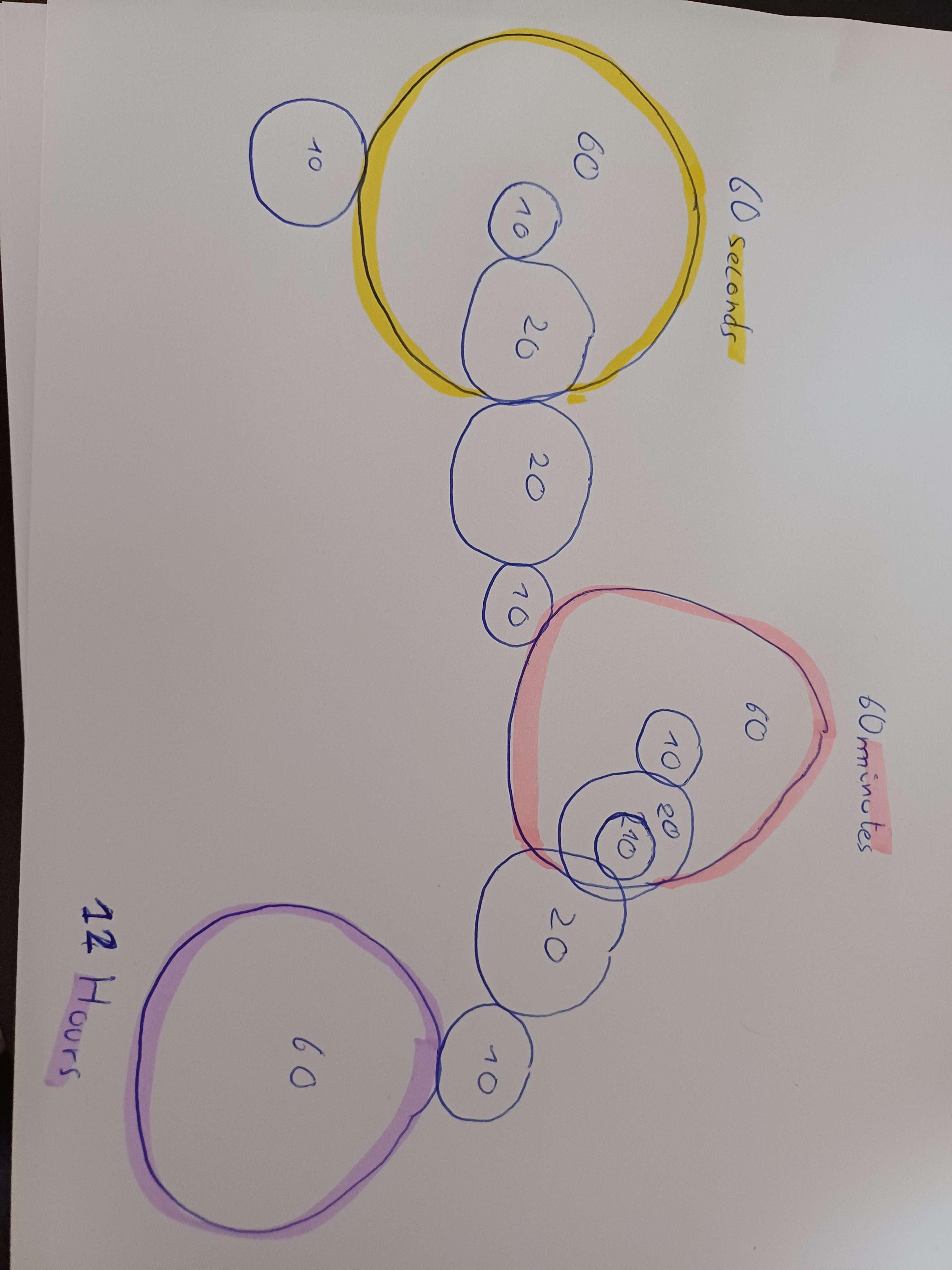
Our sketch
05/12/2025 at 15:36 • 0 comments![]()
-
Assembly(May 9th)
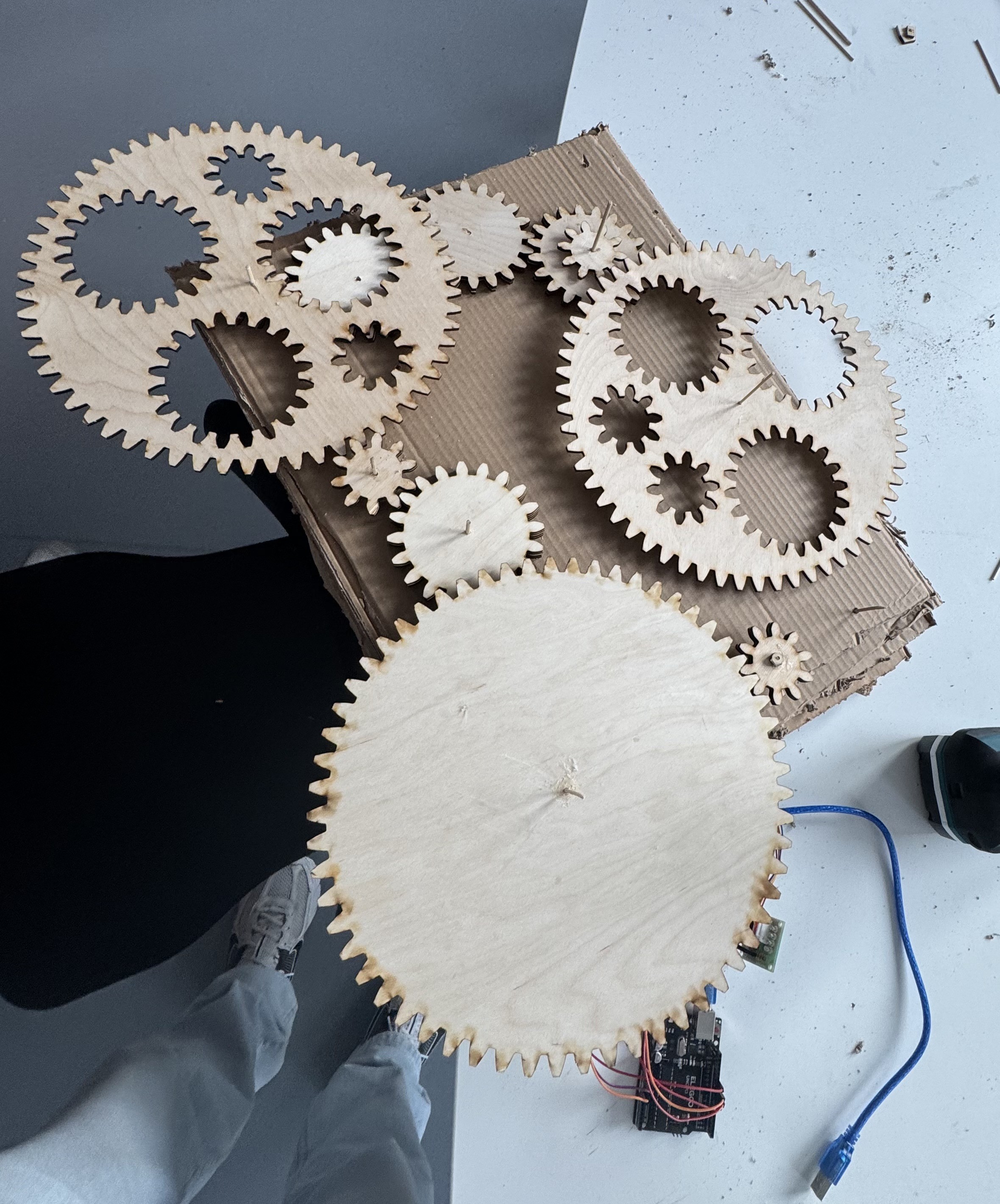
05/12/2025 at 15:34 • 0 comments![]()
Raphaël and I got together on Friday, May 9th, to assemble the clock parts and see if they finally worked.
We had a lot of complications, both in terms of gear supply and the solidity of the axes around which our gears are fixed. What's more, the size of the gears doesn't allow them to be perfectly horizontal. What's more, the gears' toothing means we have to place them very precisely to prevent the mechanism from jamming.
All that's left to do is place the hands and indexes to read the time. -
Clock(May 6th)
04/29/2025 at 11:21 • 0 commentsIn this session, we began integrating the motor that will drive the entire clock. We used a stepper motor (28BYJ-48) controlled by an Arduino to achieve precise and slow rotation—one full turn per minute.
We uploaded a simple test script to rotate the motor exactly 360° in 60 seconds. We mounted the first gear (seconds) directly on the motor shaft and observed its performance.
The test was successful: the motor ran smoothly and maintained consistent speed. This confirmed that the motor is suitable to serve as the driving force for the entire mechanism. Next, we plan to connect the gear train and observe the transmission to the minute gear.
![]()
-
Clock(April 29th)
04/29/2025 at 11:10 • 0 commentsOnce the gear models were ready, we exported them as SVG files and prepared them for laser cutting but this part took a long time because there were problems with the files containing the gears on 360 fusion . We used 3mm plywood for the prototypes.
The laser cutter allowed us to produce gears with very precise tooth profiles. We adjusted the power and speed settings to avoid burning or warping the edges. After cutting, we manually sanded and cleaned the pieces to ensure a smooth rotation.
Seeing the wooden gears come to life was a big milestone it gave us the first physical components of our future clock. We then began testing the gear meshes to verify alignment and motion transfer.
-
Clock(April 8th)
04/29/2025 at 11:01 • 0 commentsWith our project back on track, we focused on designing the gear system required to transmit motion from the seconds gear (1 rotation per minute) to the minute gear (1 rotation per hour), and then to the hour gear (1 rotation every 12 hours).
Due to the constraint that no gear can have more than 60 teeth (because our model will be too big otherwise), we had to carefully calculate the gear ratios. After testing different configurations, we settled on multi-stage gear trains to achieve the necessary reductions.
Using Fusion 360, we created digital models of each gear and ensured that the teeth meshed correctly. We double-checked the spacing and pitch diameter for each gear pair to avoid slippage or backlash.
-
Clock(March 18th)
04/29/2025 at 10:51 • 0 commentsAfter evaluating the feasibility and educational value of both ideas, we decided to return to our original project: designing a fully mechanical clock. We realized the clock offered more opportunities to apply precise mechanical design, gear calculations, and creative problem-solving.
In this session, we finalized our commitment to the gear-based clock and started focusing again on the mechanisms that would ensure accurate timekeeping. From this point forward, all sessions will be dedicated to building a reliable, motor-driven mechanical clock.
-
Change of project(March 11th)
03/04/2025 at 10:00 • 0 comments![]()
![]()
![]()
Initially, we planned to build a mechanical clock powered by gears. However, after exploring the design details, materials, and complexity involved, we decided to shift our focus towards a new and exciting project: an electric frisbee launcher.
We modified our project because we discovered that there was little information available on mechanical clockmaking, but also because we didn't think it was an easy project to carry out. Furtheremore, a lot of people wanted to make a clock, which led us to change the project.
During today's session, we created detailed plans for our electric frisbee launcher, deciding to use a single motor for simplicity and efficiency. The launcher will operate using a single motor-driven wheel that spins rapidly, transferring kinetic energy to the frisbee and launching it accurately and consistently.
-
Clock(March 4th)
03/04/2025 at 09:53 • 0 commentsToday, we made progress on our exciting project of creating a mechanical clock with gears. We started by exploring the details of our project, using Fusion 360 to visualize and design the gears. We also created cardboard models to better understand the structure and operation of our clock.
Next, we thought about the materials to use, deciding to opt for wood due to its durability and aesthetic appeal. We discussed the number of gears needed and the number of teeth for each gear to ensure smooth and precise operation.
We made a sketch and a maquette with cardboard to visualize our project
![]()