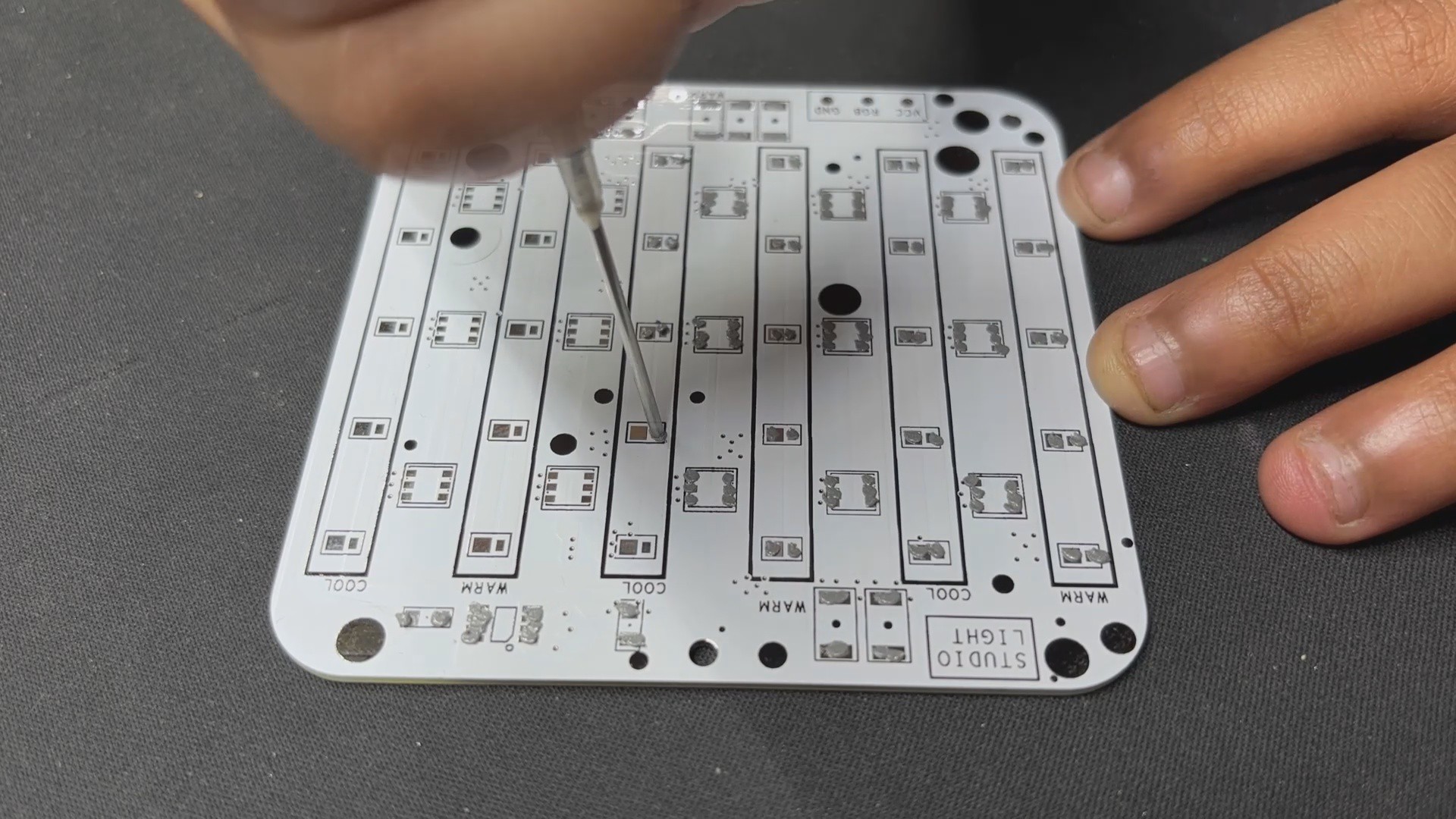
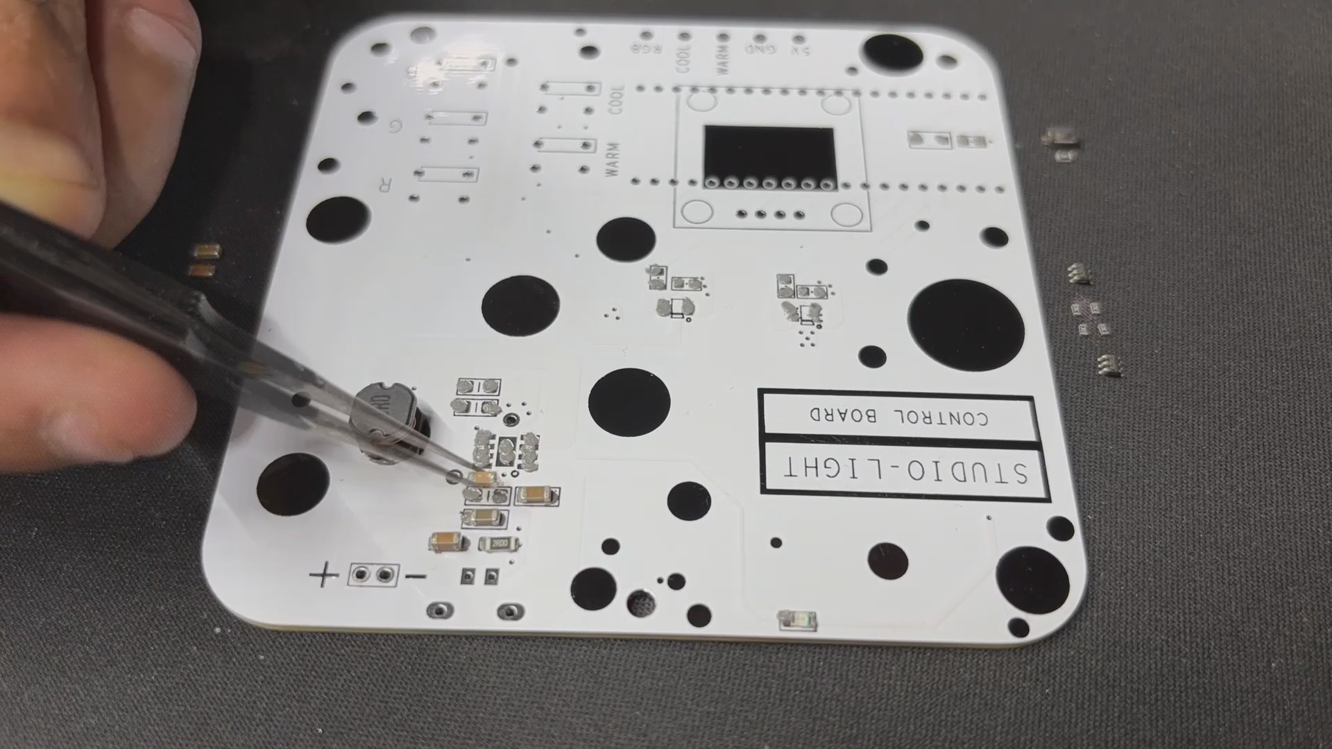
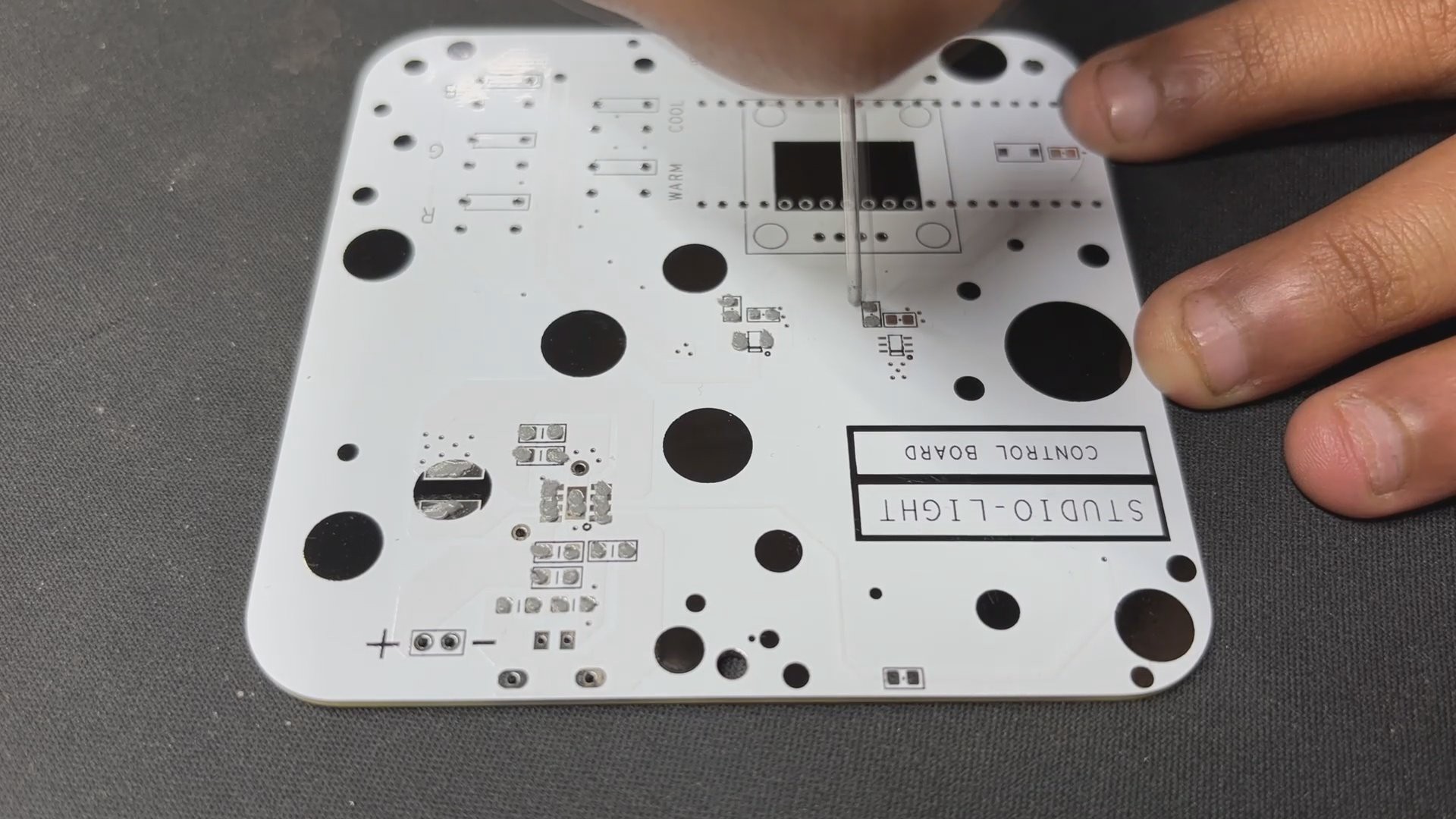
We begin the LED Board Assembly procedure by applying solder paste to each component pad. We are utilizing a solder paste dispensing syringe with 63/37 Sn/Pb solder paste.
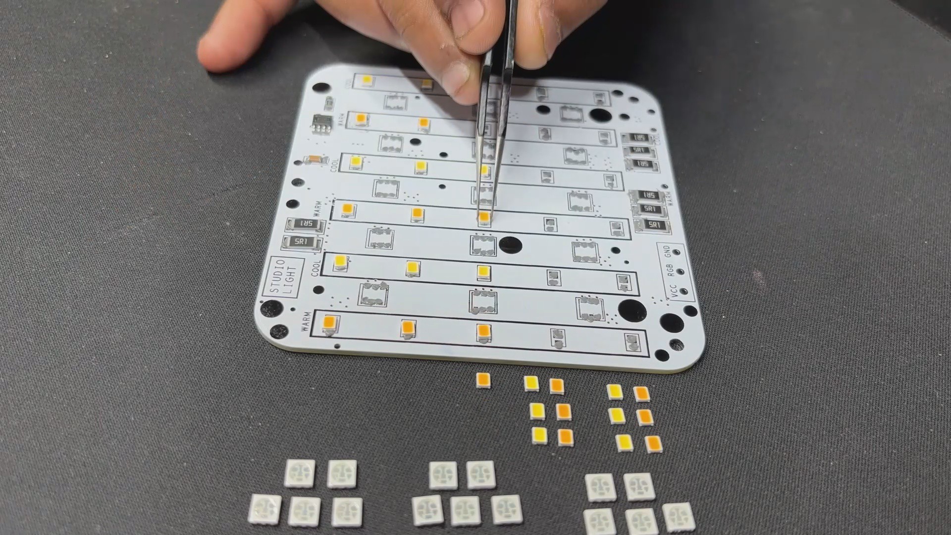
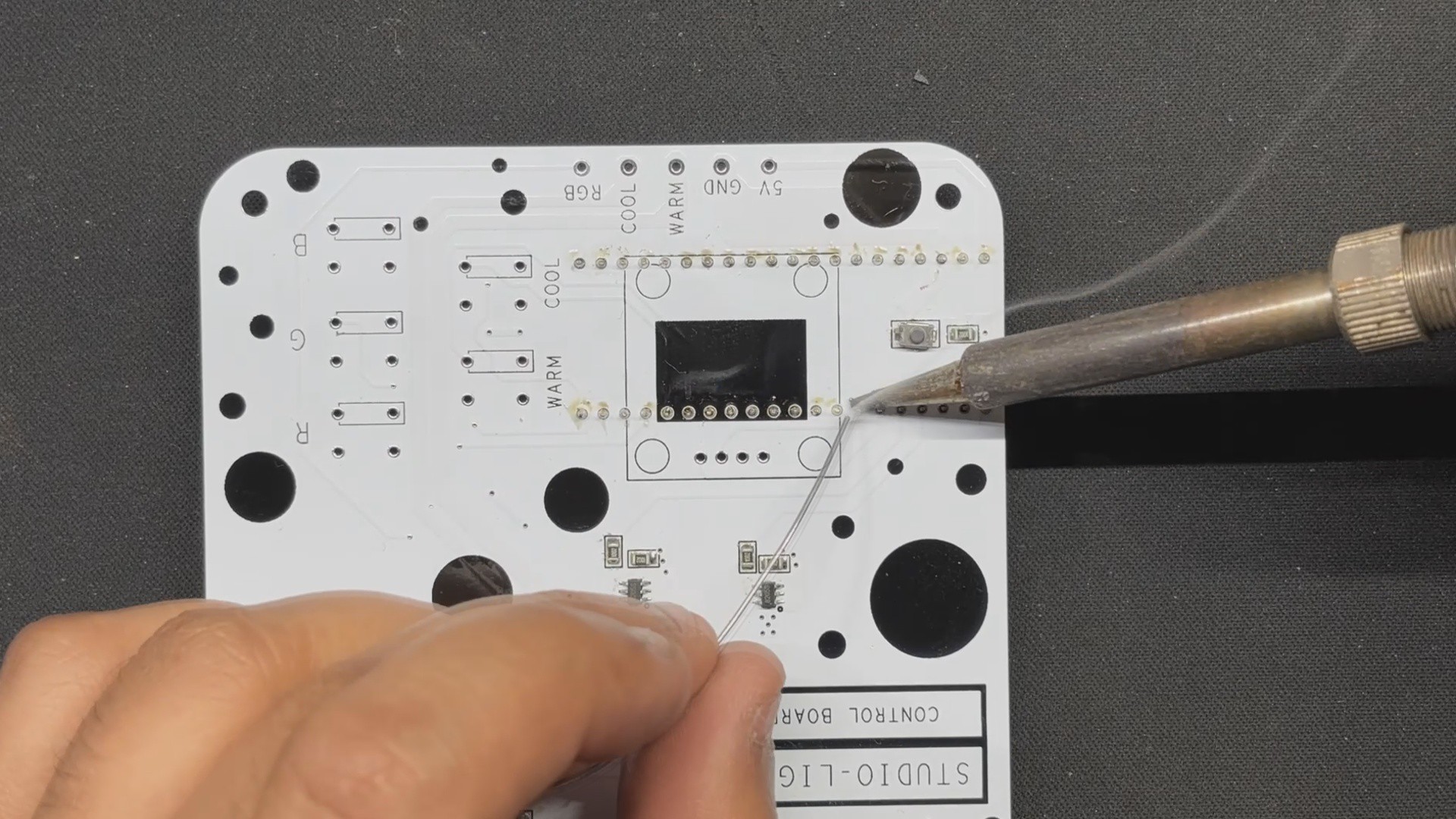
Next, we use ESD Tweezer to pick and put all of the SMD components on the PCB, which included 15x Cool White 2835 LEDs, 15x Warm White 2835 LEDs, 15x RGB LEDs, the WS2811 IC, a pair of 2512 package resistors, and a decoupling capacitor for the WS2811 IC.
We then carefully lifted the whole circuit and placed it on our Reflow hotplate, which heated the PCB below until the solder paste melted. Solder paste melts and all smd components are attached to their pads as soon as the PCB achieves this melting temperature of approximately 190° C.
2
PCB Assembly: PICO DRIVER
We begin the PICO DRIVER assembly by applying solderpaste to each component pad using a solderpaste dispensing syringe.
Next, we pick and place all of the SMD components in their proper location.
Using the reflow hotplate, we heat the PCB to solder paste melting temperature in order to solder all SMD components to their respective pads.
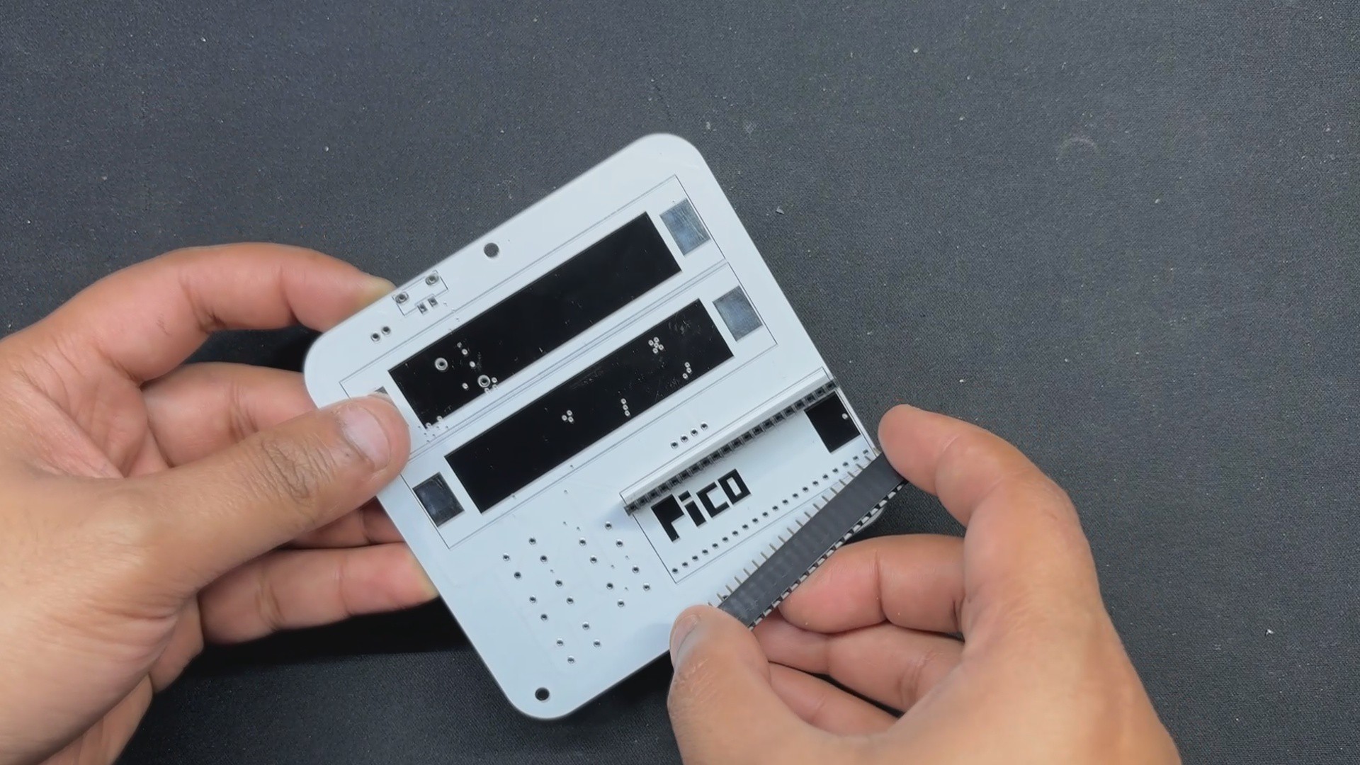
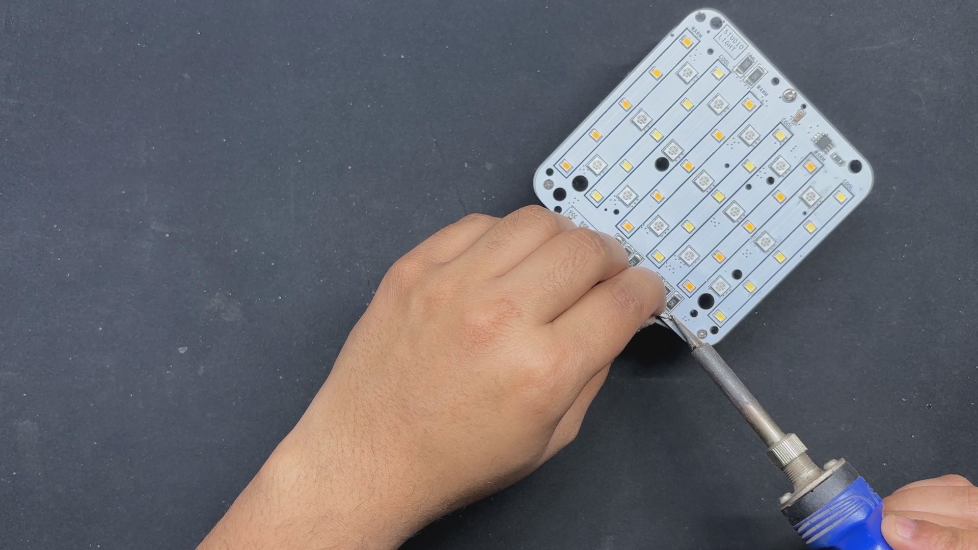
We next continue to add the THT components by attaching two CON20 Female header pin connectors to the bottom side of the PCB in the Raspberry Pi PICO location.
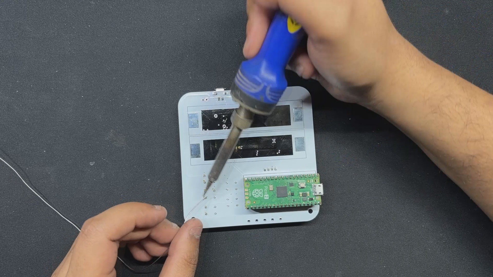
We solder the pads of the CON20 header pins with a soldering iron after turning the board over.
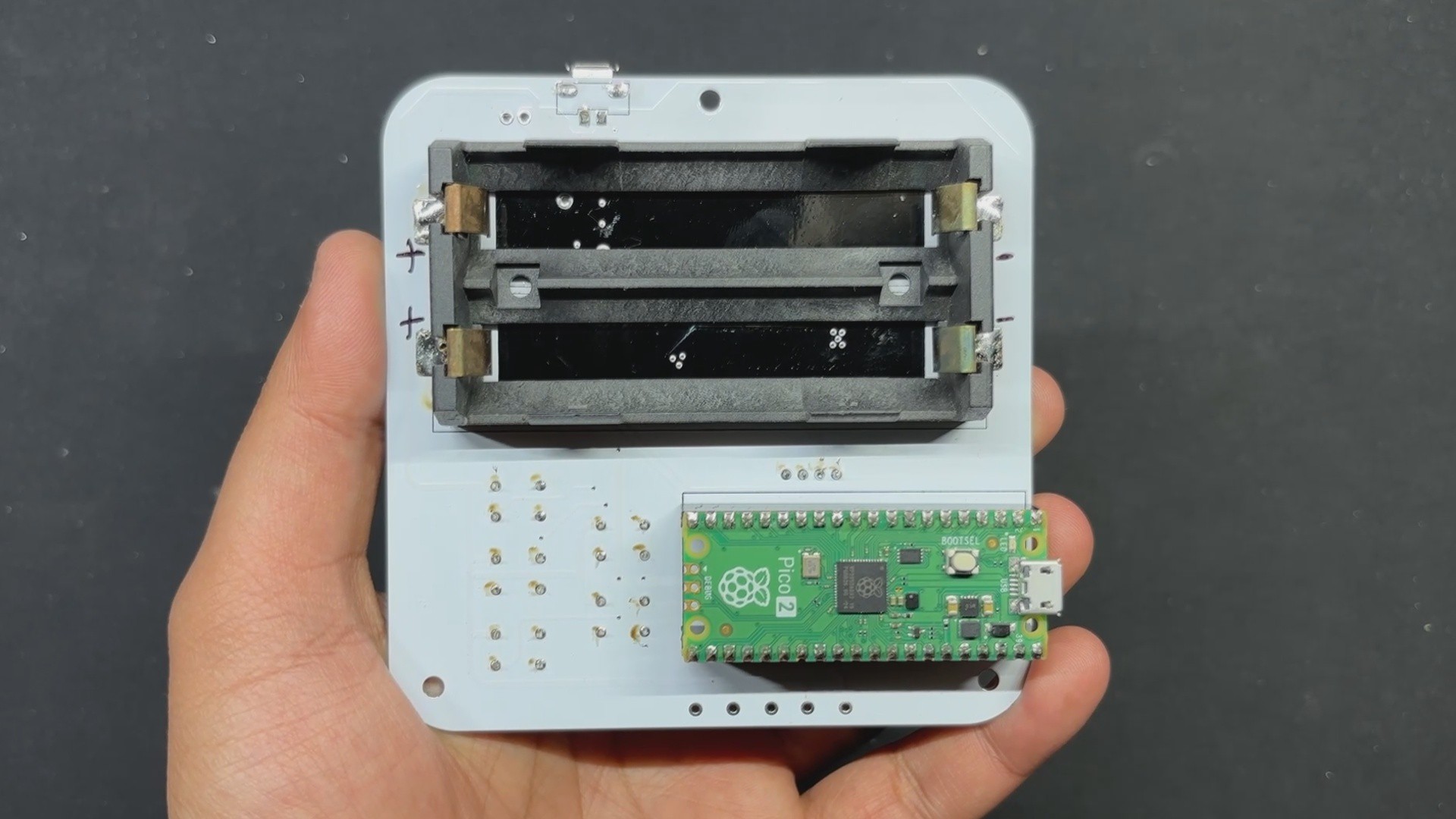
Next, we place the Raspberry Pi PICO 2 over the CON20 header pins.
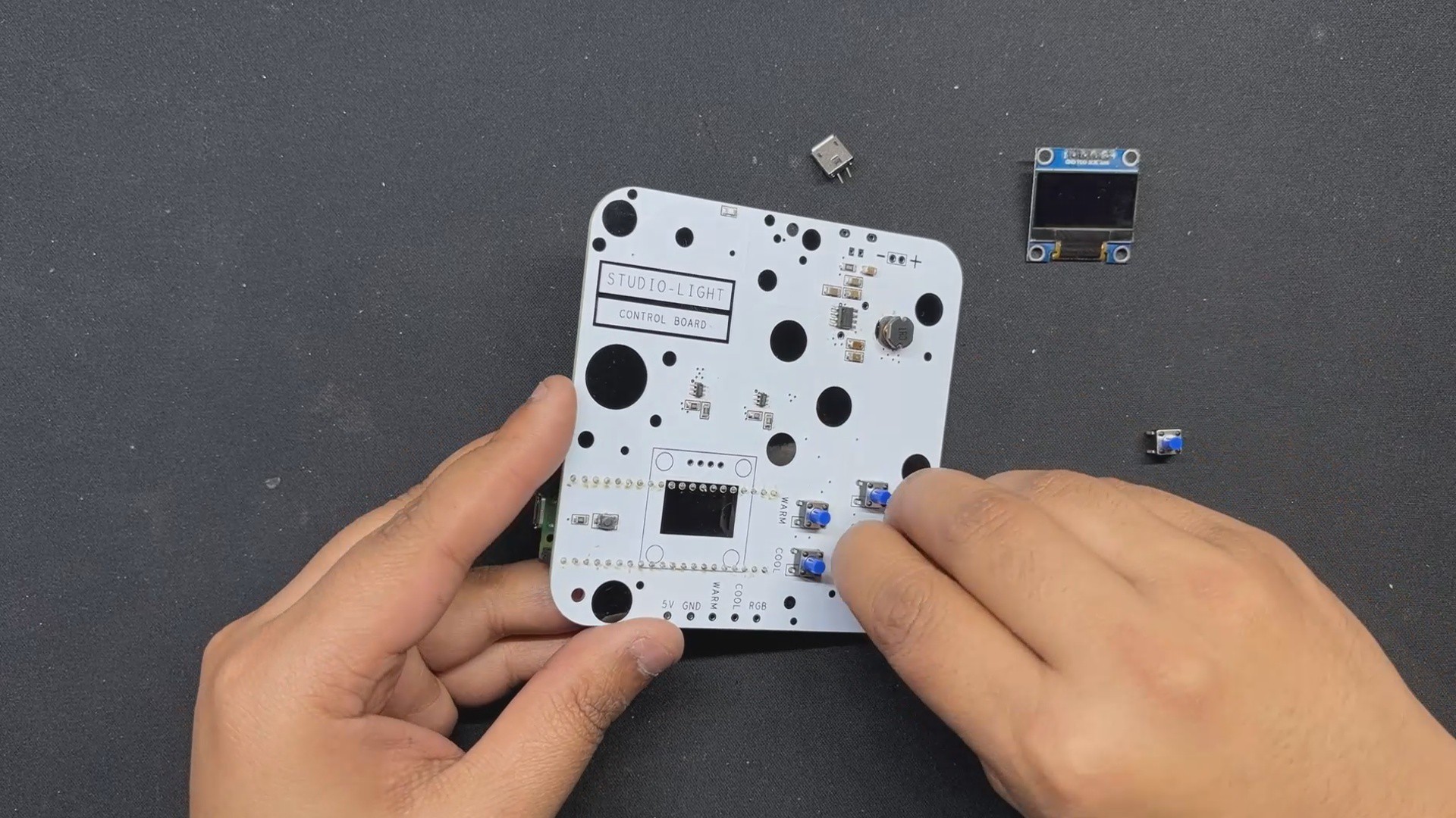
Next, we installed the display, USB port, and all five push buttons from the top side of the PCB.
Then we turn the board and solder all THT component pads with a soldering iron, ensuring that all THT components are permanently linked to the PCB.
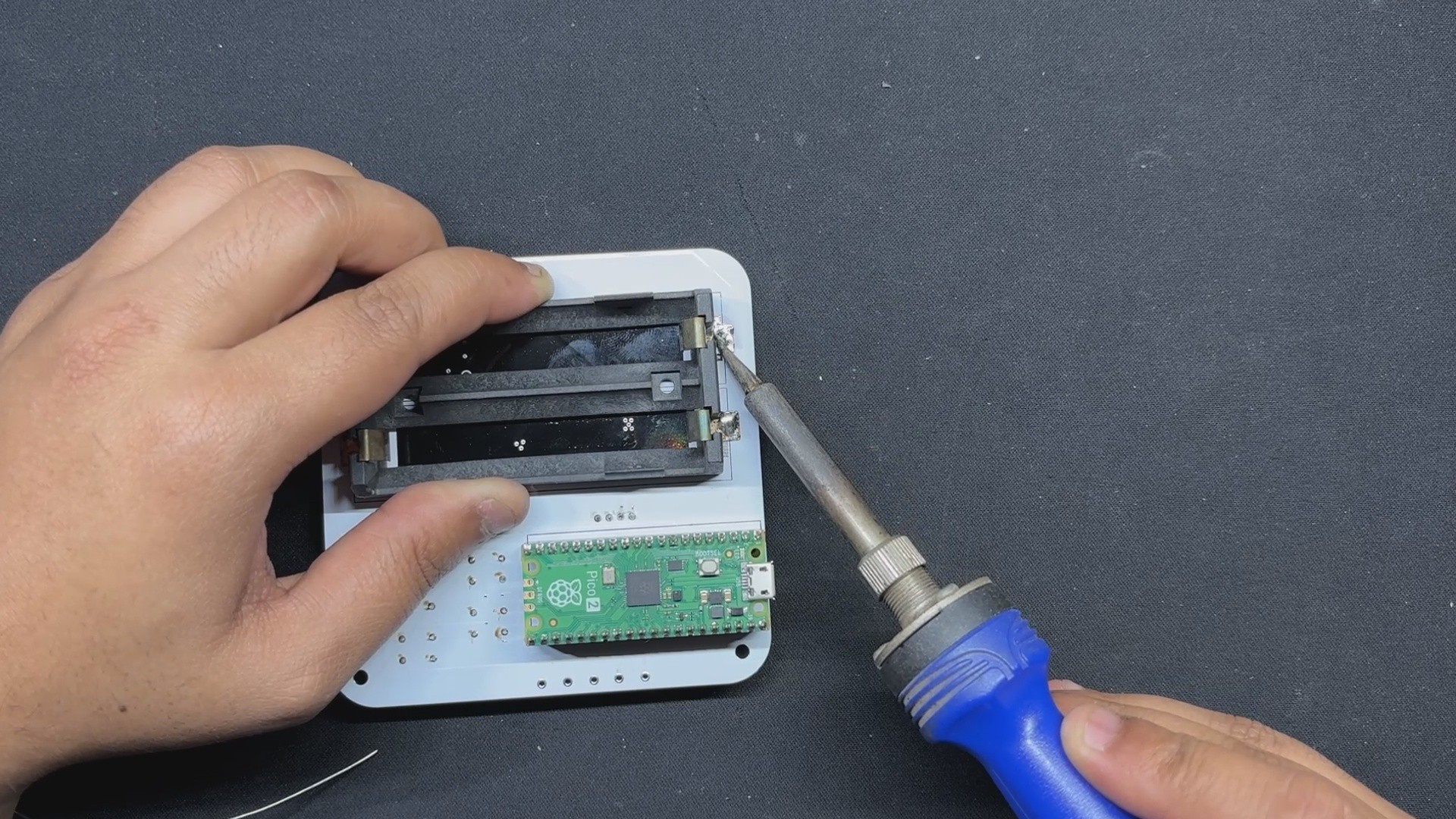
Finally, using soldering iron, we attach the lithium battery holder to the backside of the PCB.
3
Power Source/Testing Driver Board
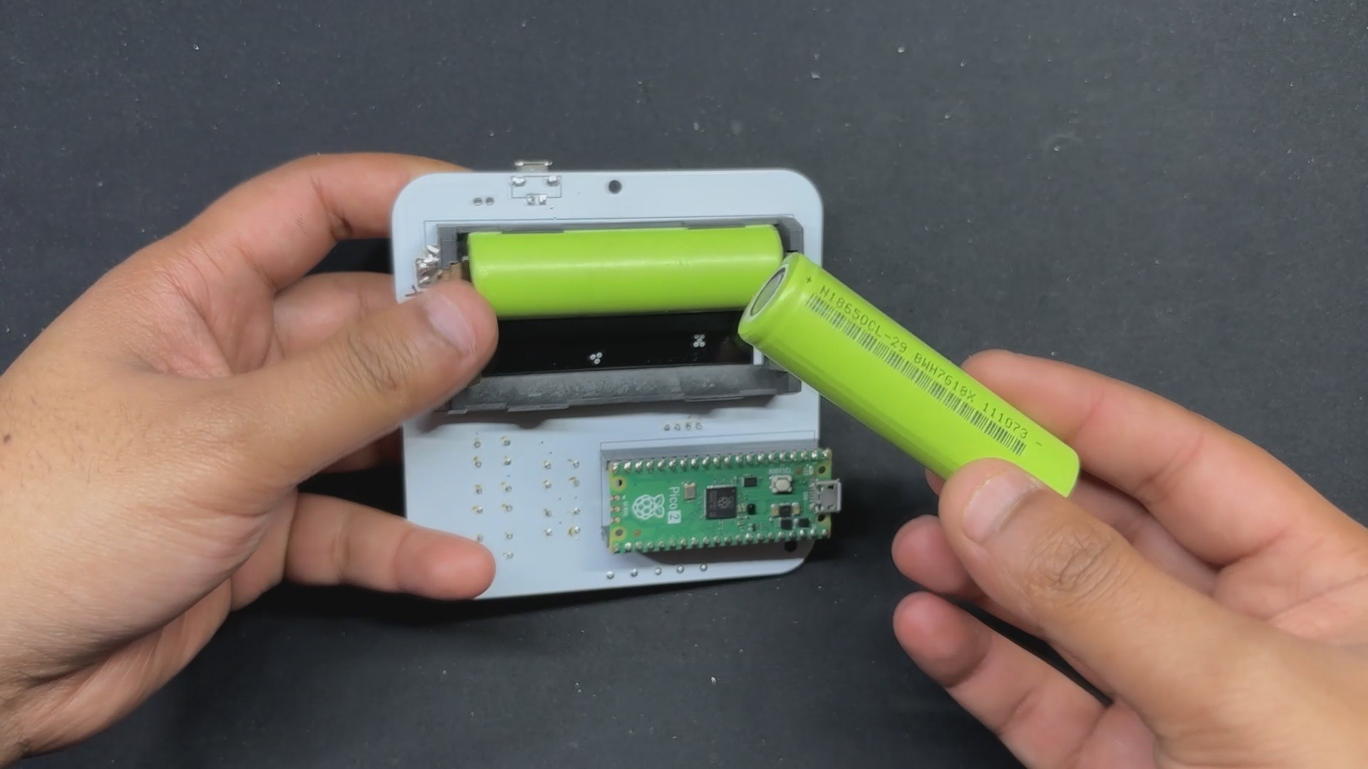
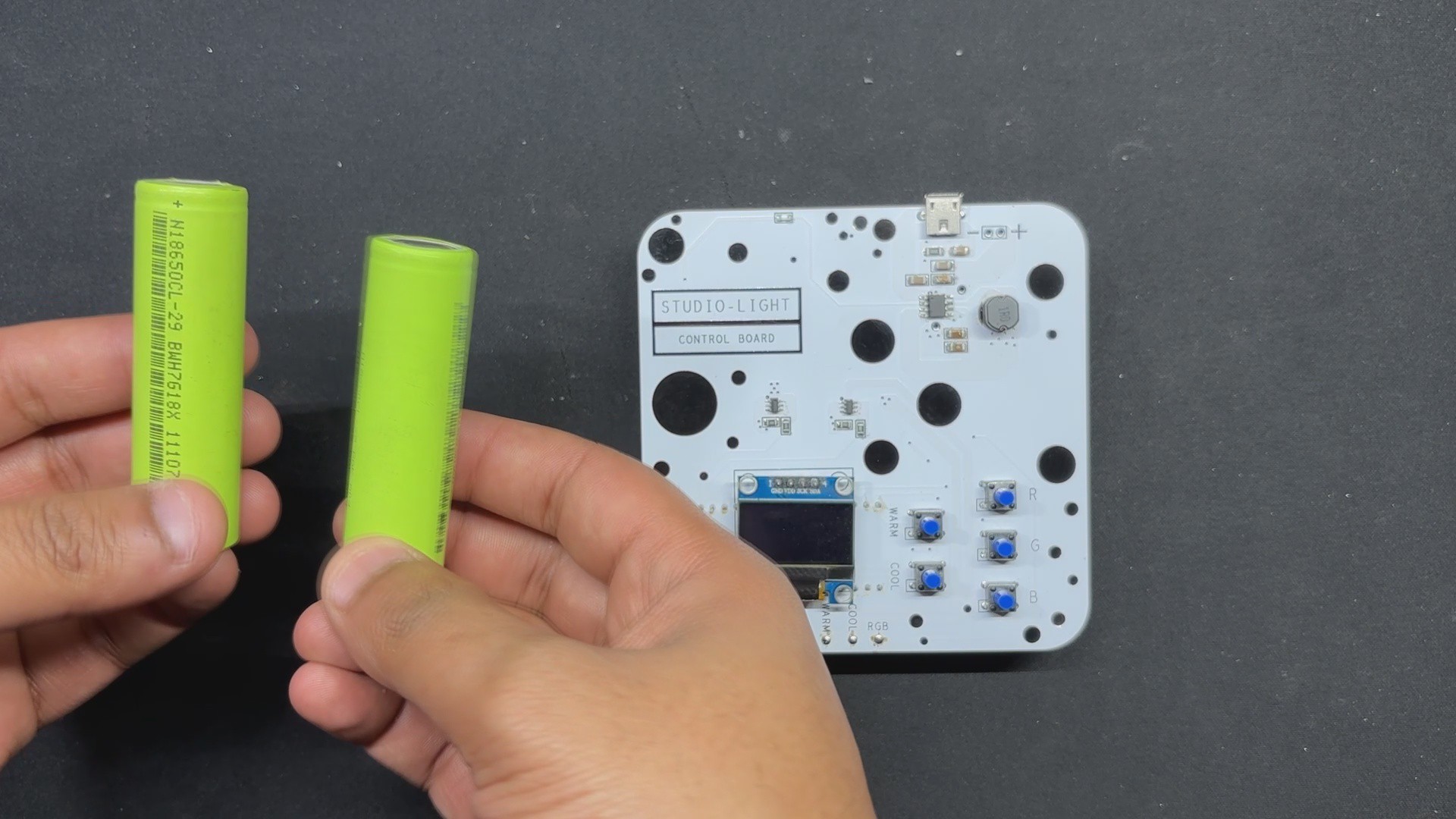
We are using two 3.7V 2900mAh 18650 Lithium cells in parallel to power the device, giving us a battery pack with a total capacity of 3.7V 5800mAh.
We set both cells on the Cell holder on the bottom side of the board, making sure they are in the correct position or the entire setup will short out.
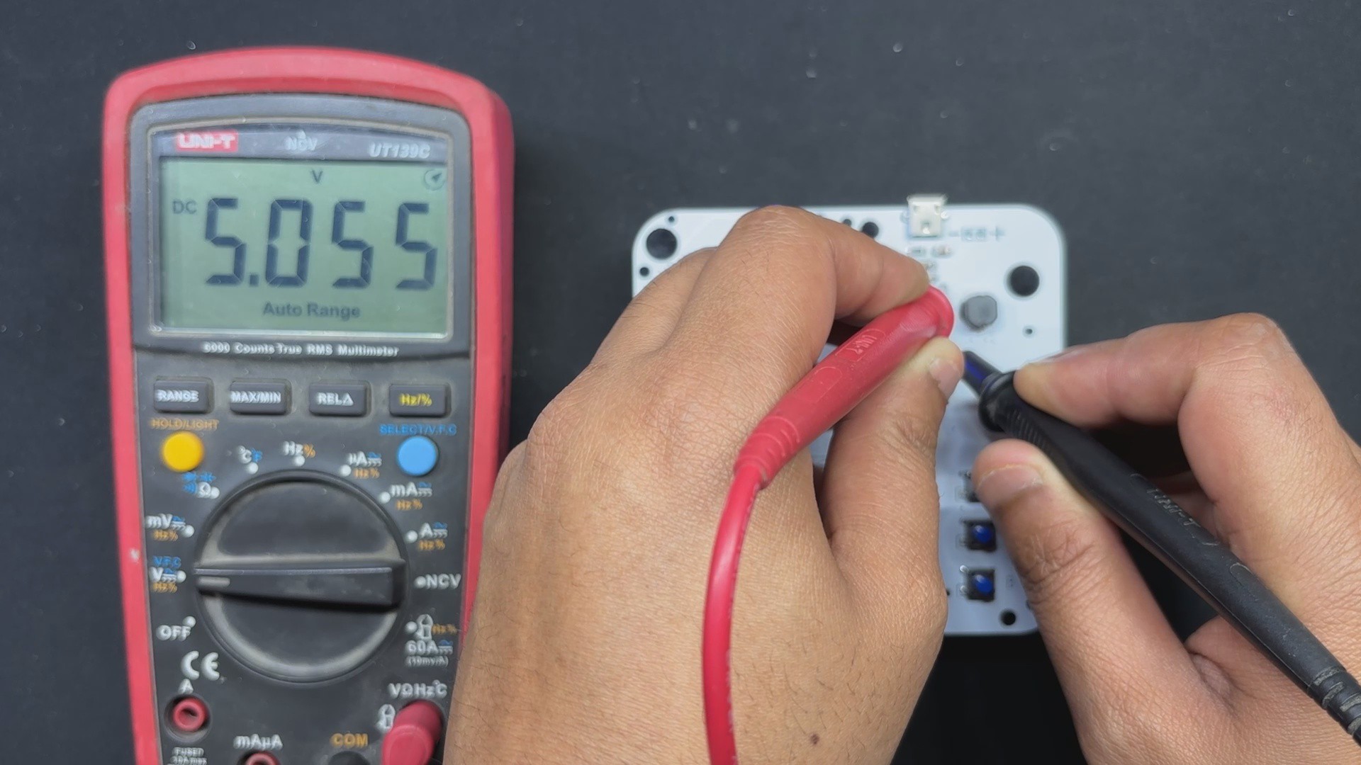
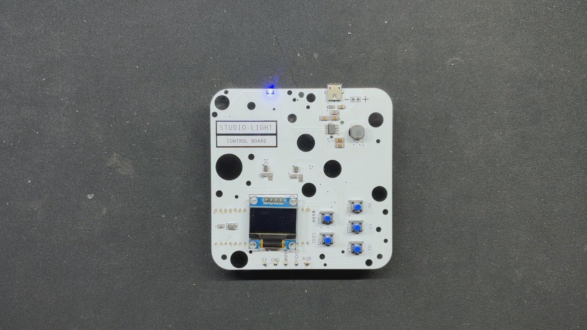
Pressing the SMD Power button once turns the device on; pressing it twice turns it off. The SMD indicator LED shows the device's ON/OFF state.
Using a multimeter, we measured the output voltage emitted by the IC, which was 5V, indicating that our setup is working and that we can now begin the final assembly process.
4
Driver board & LED board Assembly
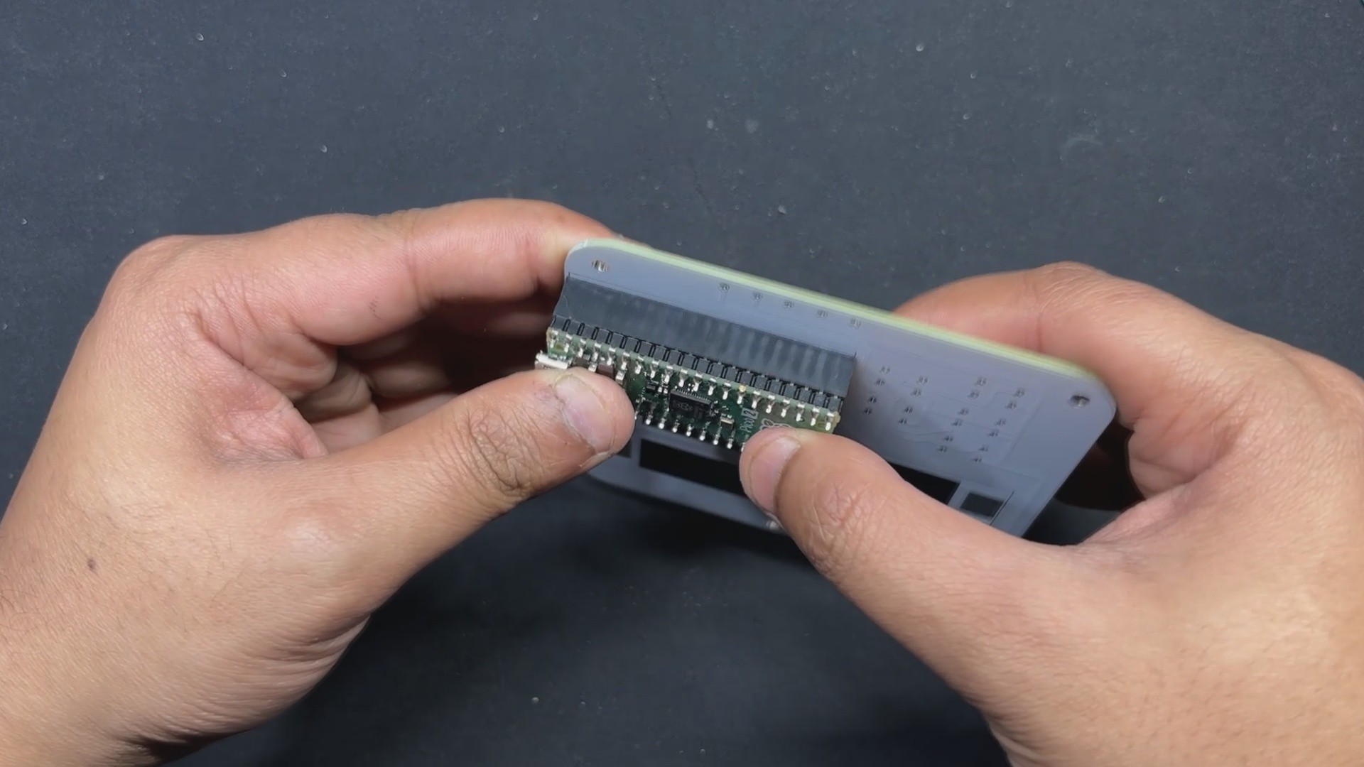
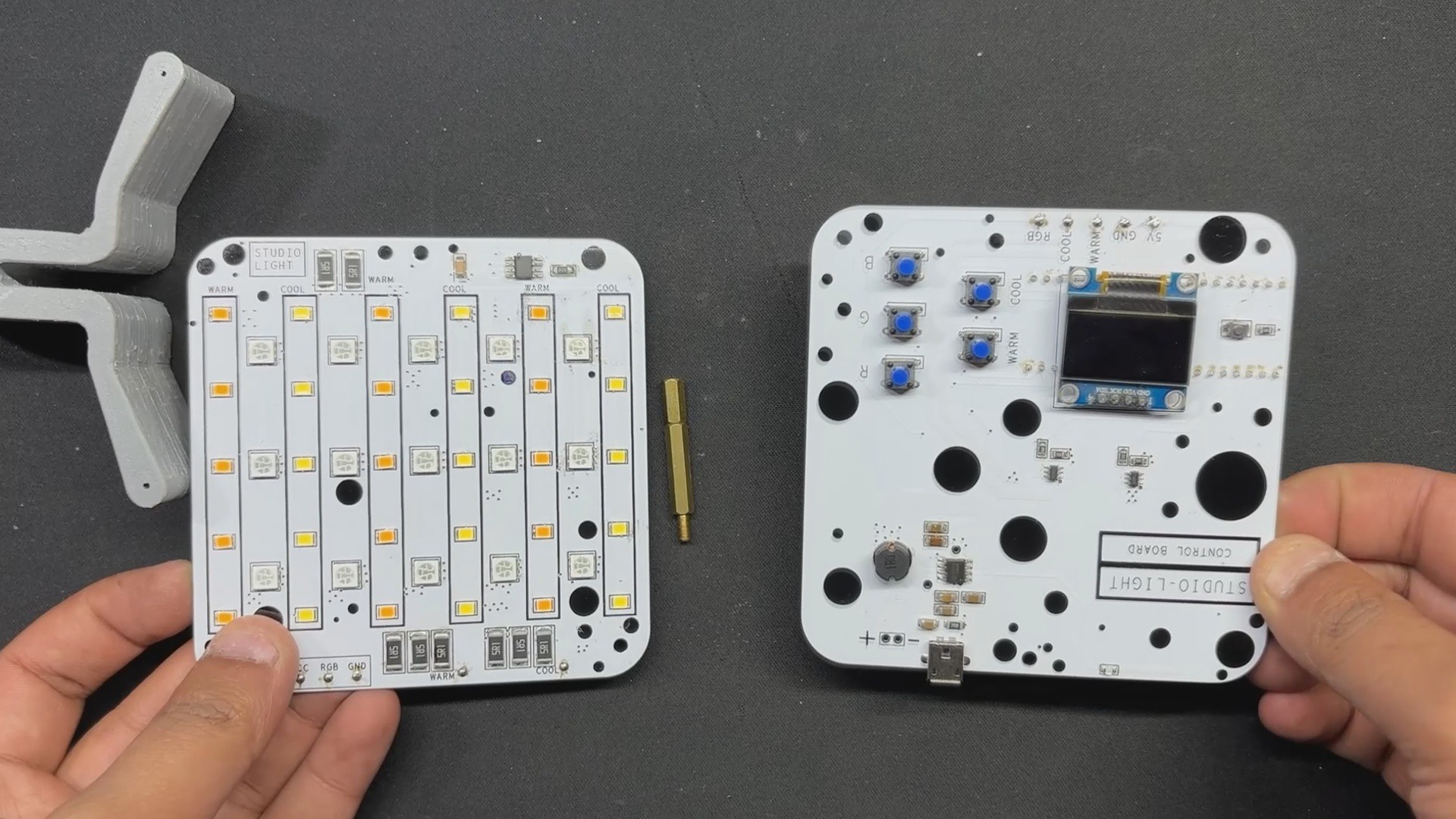
We begin the final assembly process by attaching an M3 PCB standoff to the PICO Driver board. Next, we place the LED Driver over the mounting hole of the PCB standoff and secure both PCBs together with one M3 screw.
Next, we place the 3D printed Clamp part between the two PCBs on the assembly's bottom region, and then use four M2 screws (two from each side) to connect the LED Board and PICO driver.
Next, we connect the tripod holder to the Studio light clamp section with a long M6 bolt and nut, which is used to secure both clamps together. This section is customizable and differs from tripod to tripod, so you must create your own or modify my existing design.
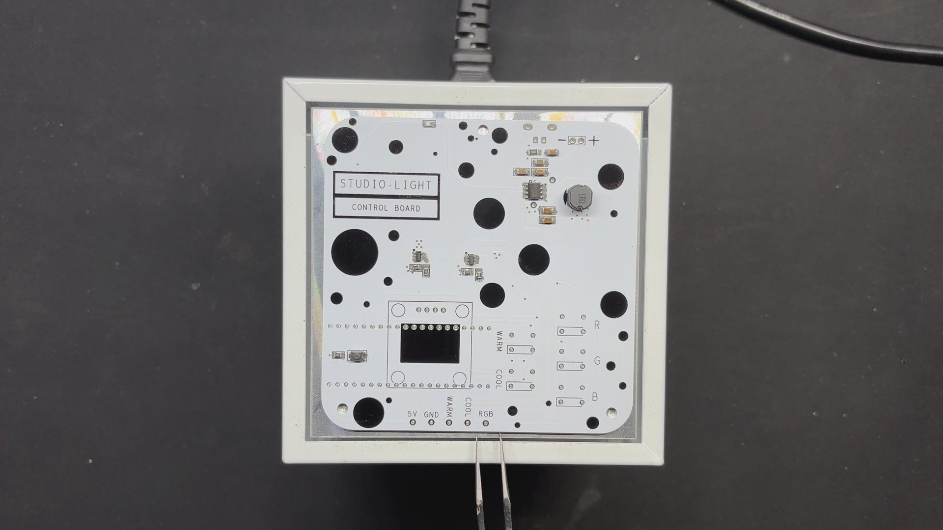
Finally, we begin the wiring process, which was straightforward. We began by connecting both boards' VCC together, followed by GND. As a result, we connected the WARM pin of the LED board to the warm pin of the PICO DRIVER, COOL to COOL, and RGB Pin to RGB Pin.
Assembly process has been completed.
5
Main Code
Here's the main code we prepared for this project and its a simple one.
#include<Wire.h>#include<Adafruit_GFX.h>#include<Adafruit_SSD1306.h>#include<FastLED.h>#define SCREEN_WIDTH 128#define SCREEN_HEIGHT 64#define OLED_RESET -1#define SCREEN_ADDRESS 0x3C // Define the I2C address for the SSD1306 OLEDAdafruit_SSD1306 display(SCREEN_WIDTH, SCREEN_HEIGHT, &Wire, OLED_RESET);
// Define the number of LEDs and data pin for WS2812B#define NUM_LEDS 1#define WS2812B_PIN 6
CRGB leds[NUM_LEDS];
// Define the GPIO pins for other LEDs#define WARM_WHITE_PIN 2#define COOL_WHITE_PIN 3// Define the GPIO pins for buttons#define WARM_WHITE_BUTTON 11#define COOL_WHITE_BUTTON 12#define RED_BUTTON 13#define GREEN_BUTTON 14#define BLUE_BUTTON 15// Define brightness levels#define BRIGHTNESS_LEVELS 5int warmWhiteBrightness = 0;
int coolWhiteBrightness = 0;
// Keep track of button statesint lastWarmWhiteButtonState = HIGH;
int lastCoolWhiteButtonState = HIGH;
// RGB valuesint rValue = 0;
int gValue = 0;
int bValue = 0;
voidsetup(){
// Initialize FastLED
FastLED.addLeds<NEOPIXEL, WS2812B_PIN>(leds, NUM_LEDS);
// Initialize OLED displayif(!display.begin(SSD1306_SWITCHCAPVCC, SCREEN_ADDRESS)) {
Serial.println(F("SSD1306 allocation failed"));
for(;;);
}
display.display();
delay(2000);
display.clearDisplay();
// Set other LED pins as OUTPUT
pinMode(WARM_WHITE_PIN, OUTPUT);
pinMode(COOL_WHITE_PIN, OUTPUT);
// Set button pins as INPUT
pinMode(WARM_WHITE_BUTTON, INPUT_PULLUP);
pinMode(COOL_WHITE_BUTTON, INPUT_PULLUP);
pinMode(RED_BUTTON, INPUT_PULLUP);
pinMode(GREEN_BUTTON, INPUT_PULLUP);
pinMode(BLUE_BUTTON, INPUT_PULLUP);
}
voidloop(){
// Read the state of each buttonint warmWhiteState = digitalRead(WARM_WHITE_BUTTON);
int coolWhiteState = digitalRead(COOL_WHITE_BUTTON);
int redState = digitalRead(RED_BUTTON);
int greenState = digitalRead(GREEN_BUTTON);
int blueState = digitalRead(BLUE_BUTTON);
// Check for warm white button pressif (warmWhiteState == LOW && lastWarmWhiteButtonState == HIGH) {
warmWhiteBrightness = (warmWhiteBrightness + 1) % BRIGHTNESS_LEVELS;
analogWrite(WARM_WHITE_PIN, warmWhiteBrightness * 255 / (BRIGHTNESS_LEVELS - 1));
}
lastWarmWhiteButtonState = warmWhiteState;
// Check for cool white button pressif (coolWhiteState == LOW && lastCoolWhiteButtonState == HIGH) {
coolWhiteBrightness = (coolWhiteBrightness + 1) % BRIGHTNESS_LEVELS;
analogWrite(COOL_WHITE_PIN, coolWhiteBrightness * 255 / (BRIGHTNESS_LEVELS - 1));
}
lastCoolWhiteButtonState = coolWhiteState;
// Control WS2812B RGB LED and update RGB valuesif (redState == LOW) {
rValue = 255; gValue = 0; bValue = 0;
leds[0] = CRGB::Red;
FastLED.show();
} elseif (greenState == LOW) {
rValue = 0; gValue = 255; bValue = 0;
leds[0] = CRGB::Green;
FastLED.show();
} elseif (blueState == LOW) {
rValue = 0; gValue = 0; bValue = 255;
leds[0] = CRGB::Blue;
FastLED.show();
} else {
rValue = 0; gValue = 0; bValue = 0;
leds[0] = CRGB::Black; // Turn off RGB LED when no buttons are pressed
FastLED.show();
}
// Update OLED display
display.clearDisplay();
// Display RGB values
display.setTextSize(1);
display.setTextColor(SSD1306_WHITE);
display.setCursor(0, 0);
display.println(F("RGB VALUES"));
display.setCursor(0, 10);
display.print(F("R = ")); display.println(rValue);
display.setCursor(0, 20);
display.print(F("G = ")); display.println(gValue);
display.setCursor(0, 30);
display.print(F("B = ")); display.println(bValue);
// Display Cool White brightness in equal-sized box
display.setCursor(64, 10);
display.println(F("COOL WHITE"));
display.setCursor(64, 20);
display.print(F(coolWhiteBrightness * 25)); display.println(F("%"));
// Display Warm White brightness in equal-sized box
display.setCursor(64, 40);
display.println(F("WARM WHITE"));
display.setCursor(64, 50);
display.print(F(warmWhiteBrightness * 25)); display.println(F("%"));
display.display();
}
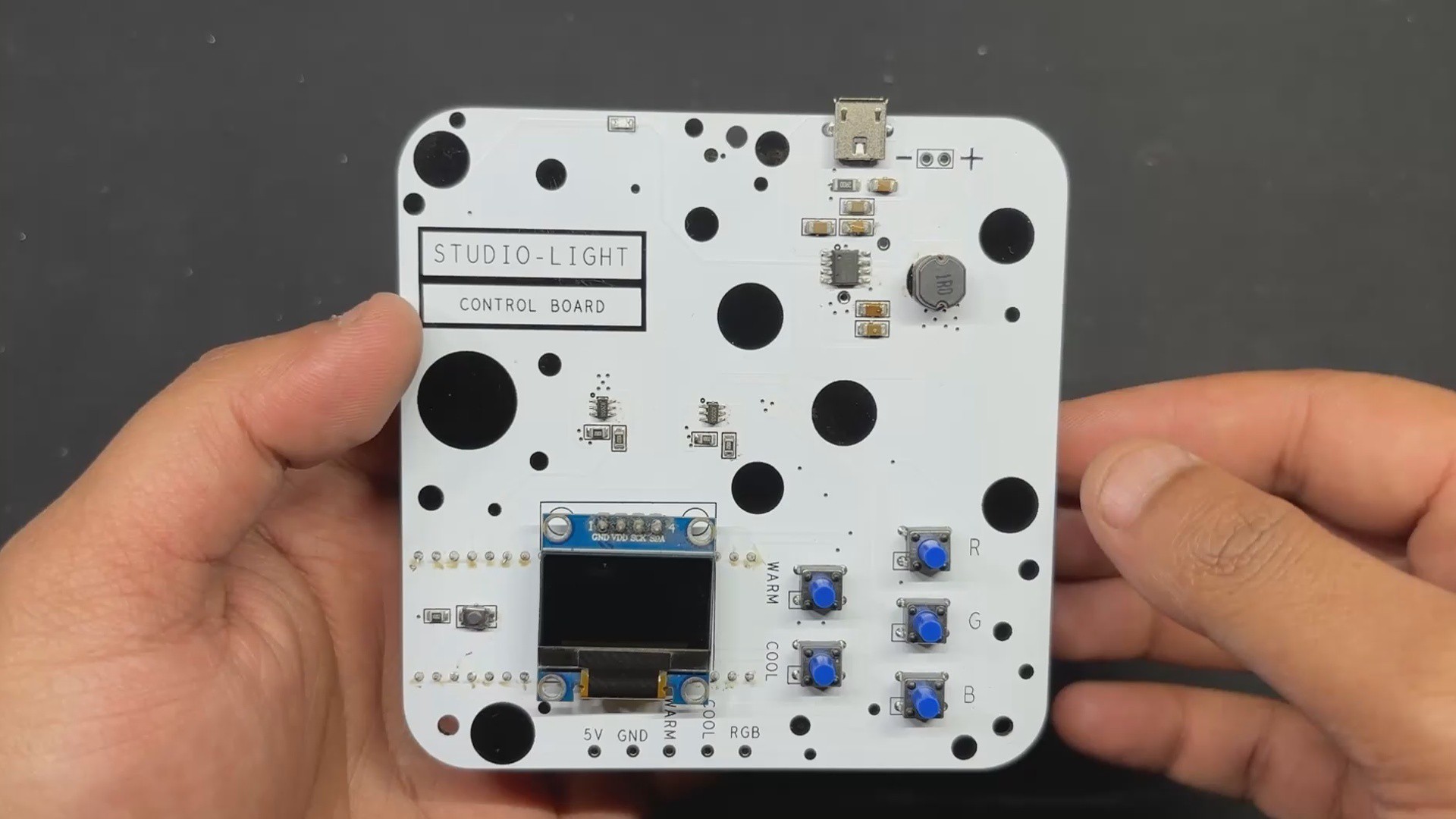
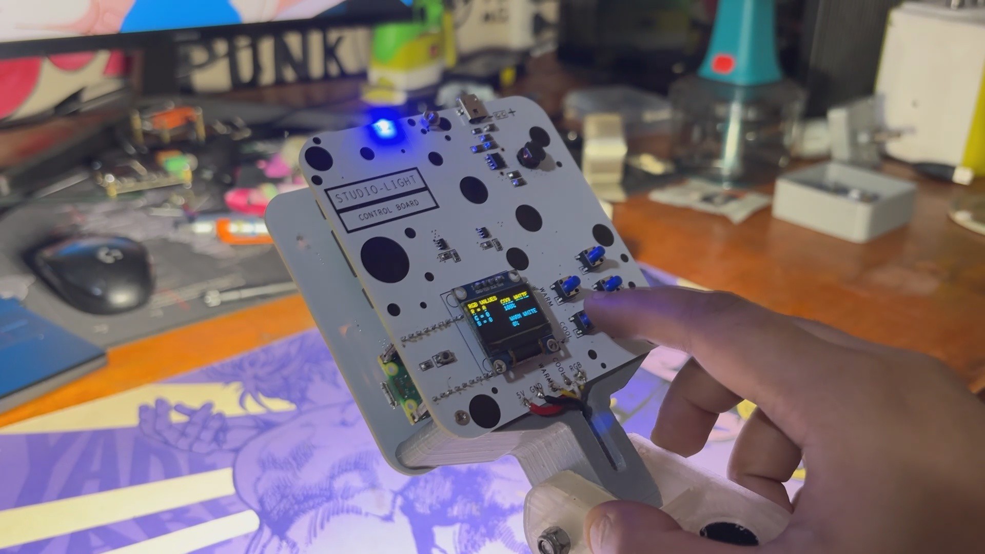
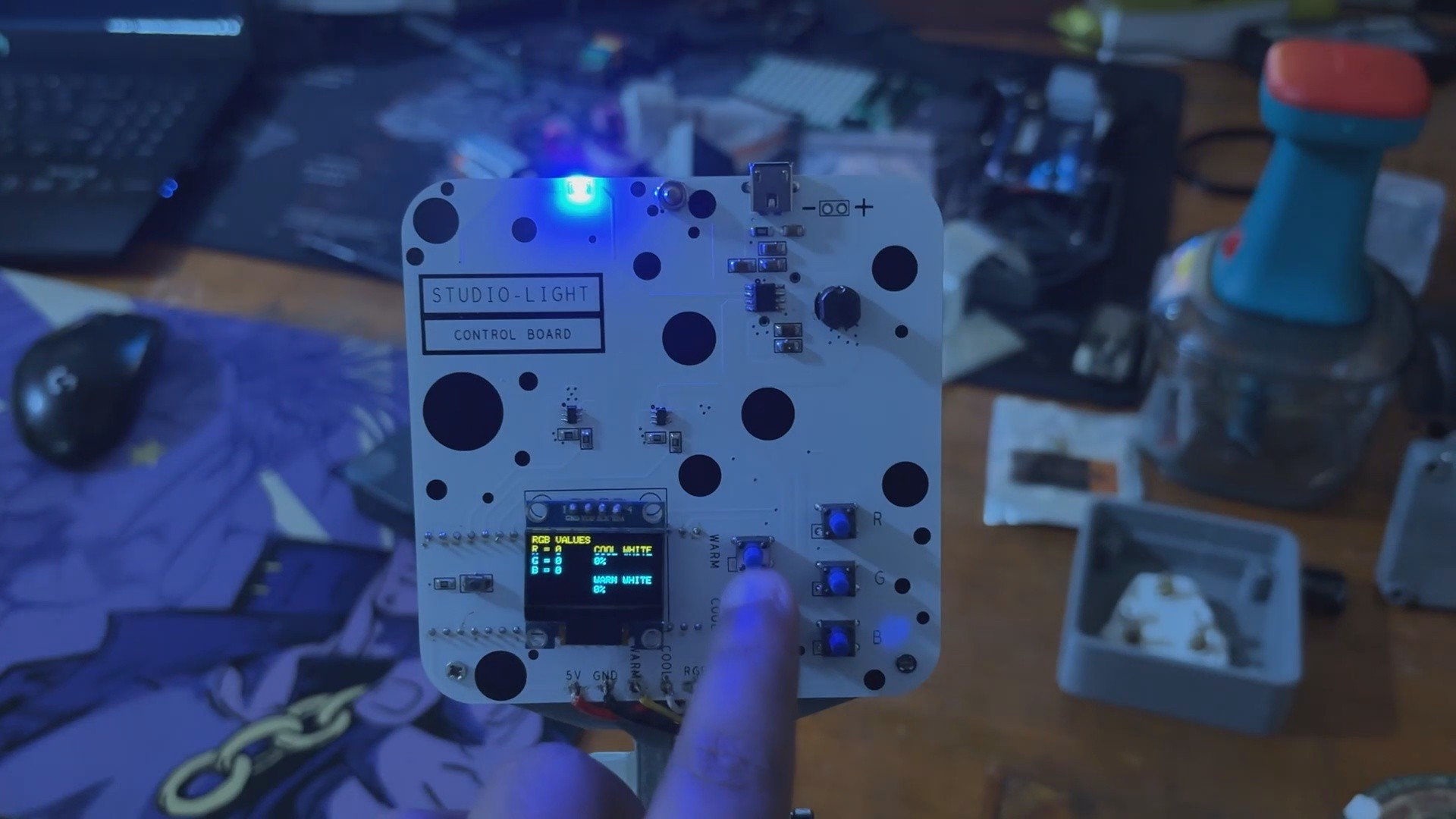
The setup consists of a Raspberry Pi PICO 2 with an OLED screen and a WS2812B RGB LED, as well as two extra LEDs (warm white and cool white), which are all connected to the Raspberry Pi Pico 2 GPIO pins.
These LEDs are controlled using buttons, which allows for interactive lighting adjustments. The FastLED library controls the WS2812B RGB LED, while the Adafruit SSD1306 library manages the OLED display.
This code allows you to regulate the brightness of warm and cold white LEDs via button presses. Each button click cycles the LED brightness through 25%, 50%, 75%, and 100%, giving you more control over the lighting.
The status of these LEDs, including their current brightness level, is presented on an OLED panel. The screen is separated into two sections: the left side displays the RGB values of the WS2812B LED, and the right side has two equal boxes.
The top box displays the brightness percentage of the cool white LED, and the bottom box displays the brightness percentage of the warm white LED. This setup ensures you always have a clear visual indication of the LED states directly on the OLED display.
6
RESULT
As we wrap up this exciting studio light project, it's clear that we've achieved a highly interactive and functional setup. The project features a WS2812B RGB LED and two additional LEDs (warm white and cool white), all controlled by buttons connected to a Raspberry Pi Pico.
This setup allows for precise control of LED brightness, with each button press cycling the warm white and cool white LEDs through 25%, 50%, 75%, and 100% brightness levels. The OLED display provides a clear and organized visualization of the current states, showing RGB values on the left and the brightness levels of the cool white and warm white LEDs on the right.
One thing we need to change in the future version is the use of the WS2811 CHIP. We utilized 15 LEDs connected in parallel, with each LED drawing 60mA, therefore 15 LEDs would draw around 900mA current, but we are using a single WS2811 chip that only supports LED current up to 18mA, which is significantly low. Meaning that our setup works, but the light is faint and cannot be used in a practical manner. This can be handled by using three mosfets as a switch (one for each color).
This issue will be addressed in an upcoming version, so stay tuned.
Overall, this project not only enhances your workspace with customizable lighting but also demonstrates the seamless integration of various components to achieve an efficient and user-friendly system.
Special thanks to HQ NextPCB for providing components that I've used in this project; check them out for getting all sorts of PCB or PCBA-related services for less cost.
Thanks for reaching this far, and I will be back with a new project soon.
 Arnov Sharma
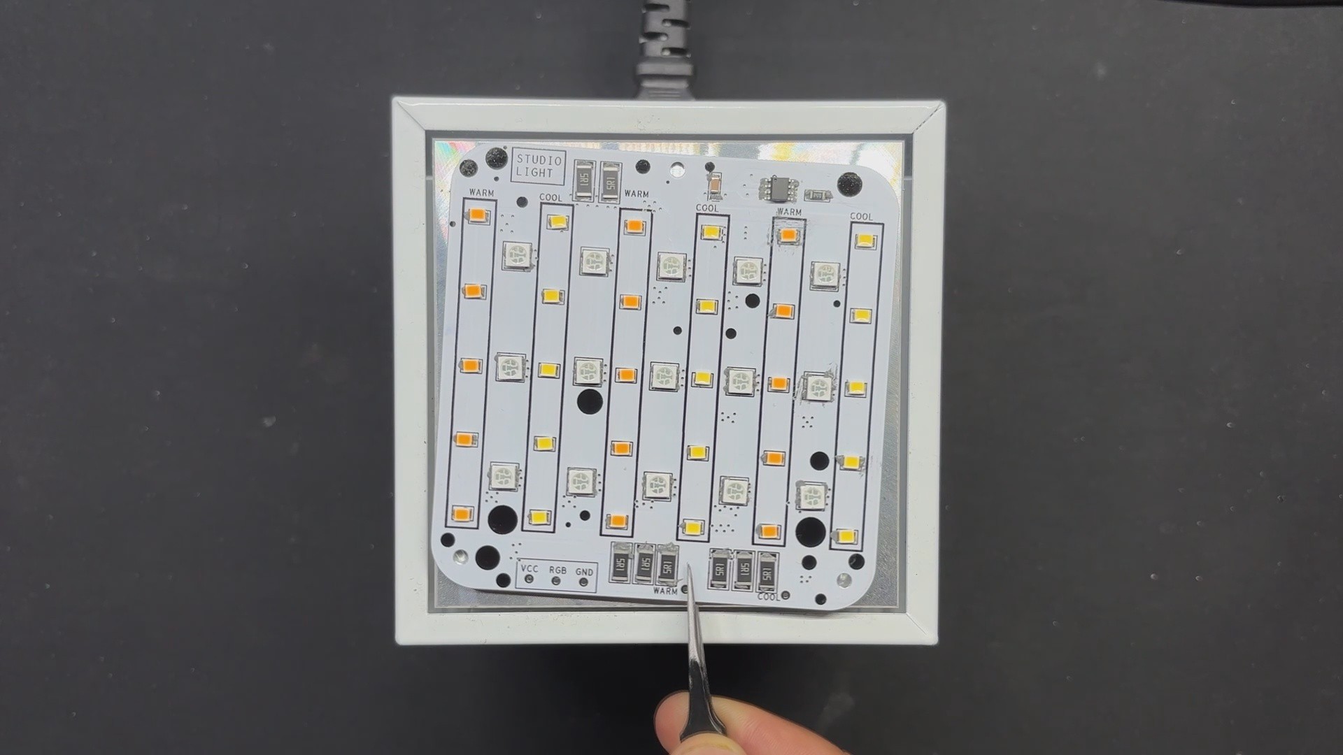


Discussions
Become a Hackaday.io Member
Create an account to leave a comment. Already have an account? Log In.