Arnov Sharma
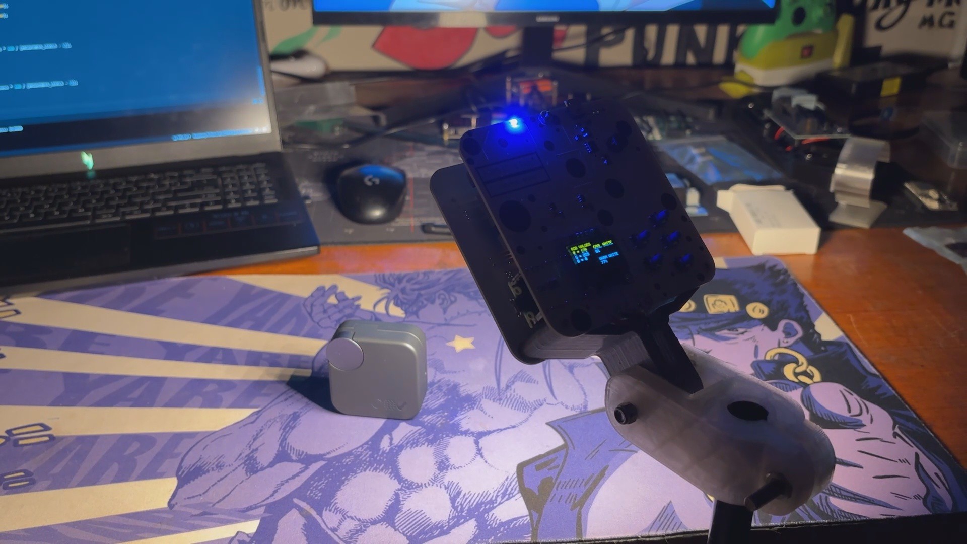
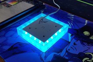
We created this project to improve the lighting in my shots, and it's an essential tool if you make YouTube videos or simply enjoy taking beautiful photos.
Model
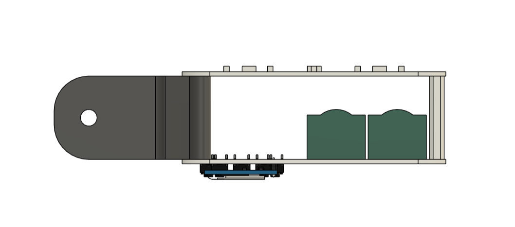
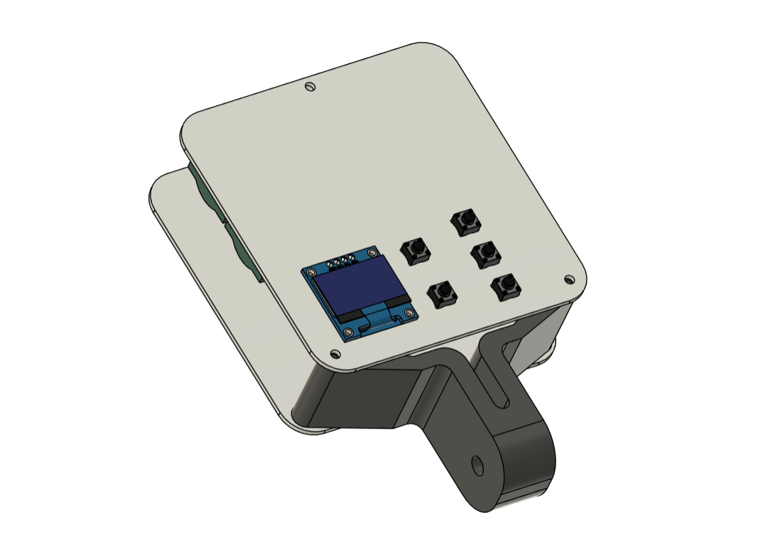
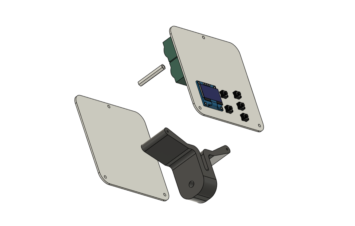
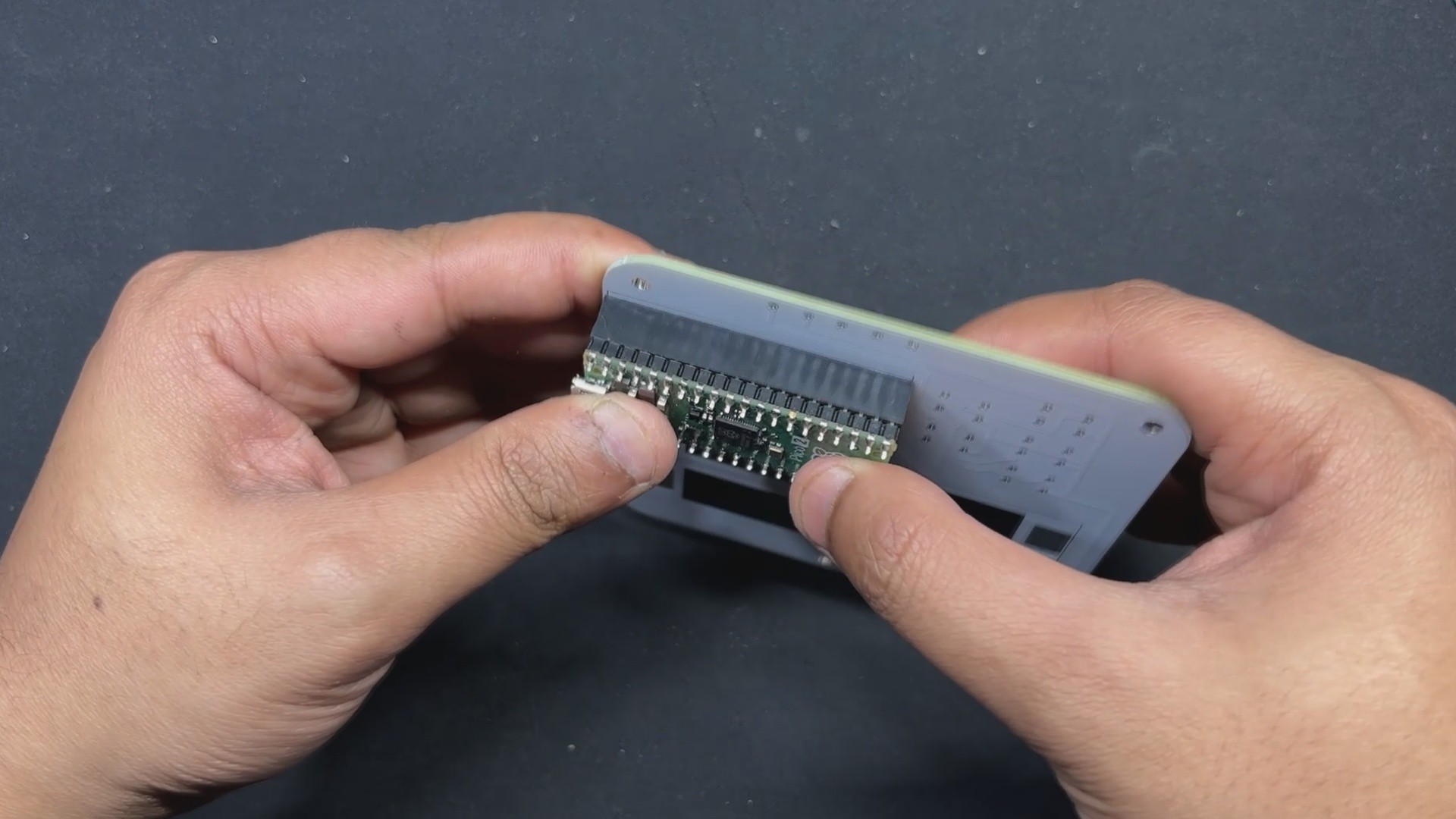
We begin this project by creating the model in Fusion 360. The model consists of up of two boards stacked together, with a single PCB standoff on top and a 3D-printed special clamp-like part on the bottom that also connects the two PCBs using M2 screws.
This clamp-like device can be used to mount this device to a tripod.
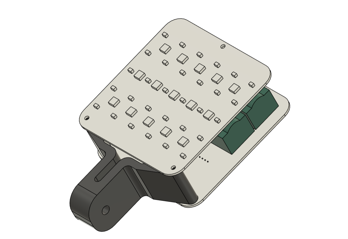
The model comprises of two PCBs: the LED board, which contains all of the SMD COOL WHITE, WARM WHITE, and RGB LEDs, as well as their load resistance.
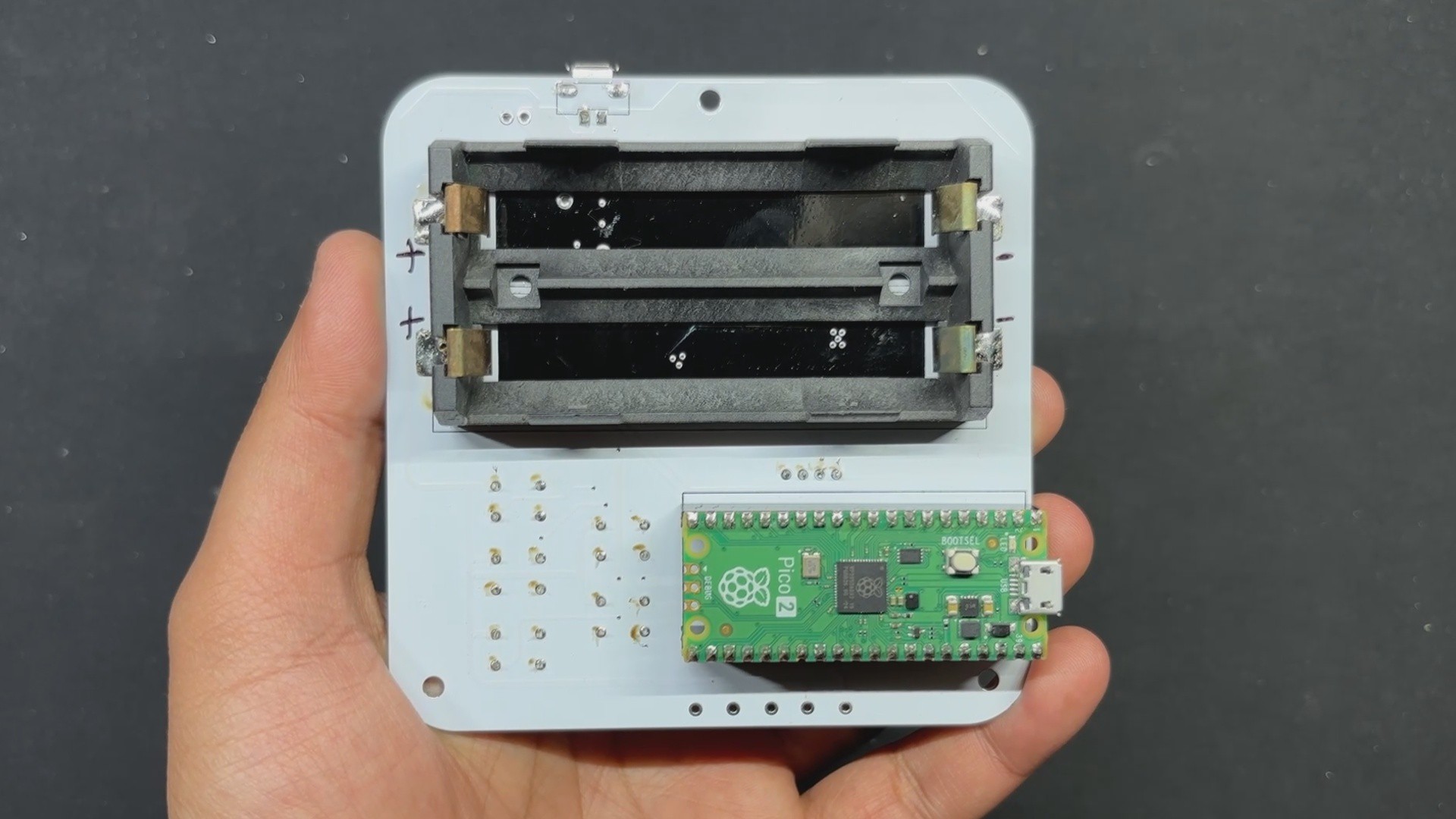
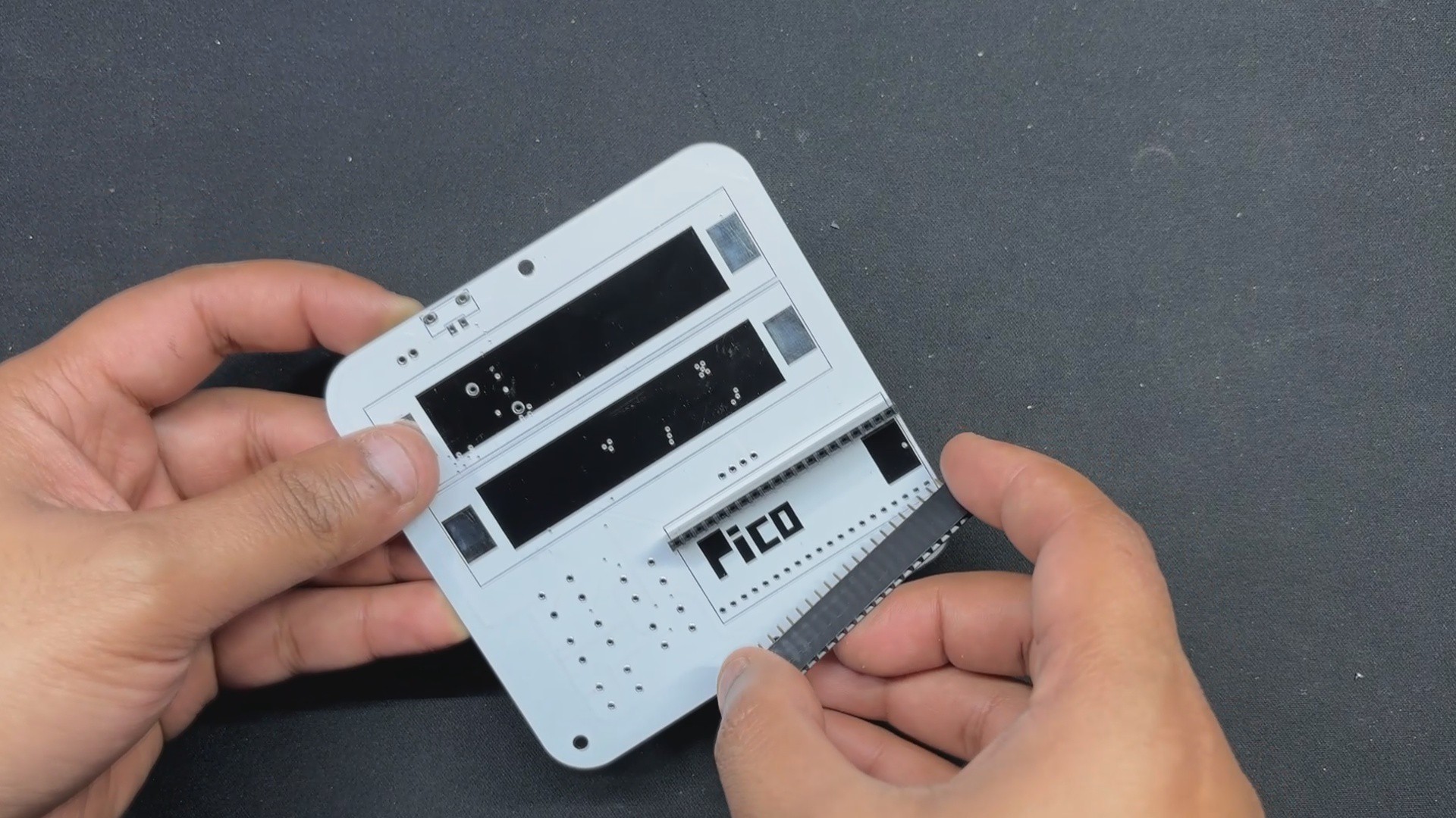
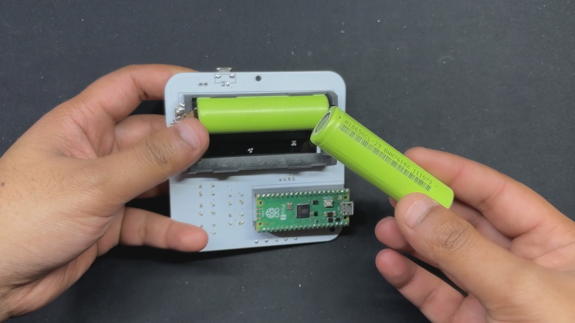
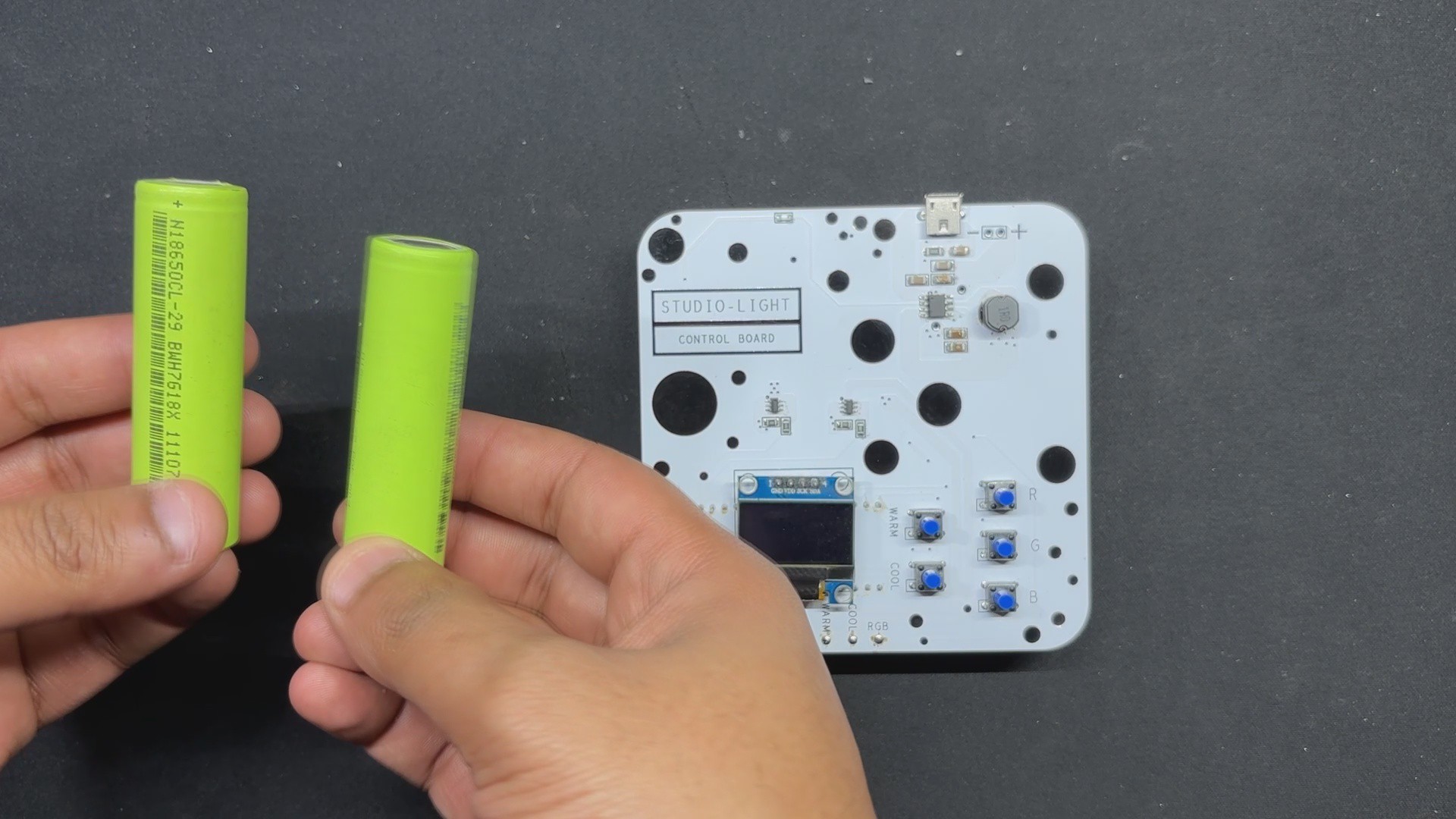
The second PCB is the PICO DRIVER board, which consists of a Raspberry Pi PICO connected by five buttons, an SSD1306 OELD screen, and two Lithium cells for power.
After finalizing the model, we exported the CLAMP mesh file and 3D printed it with a 0.4mm nozzle, 25% infill, and 0.2mm layer height.
PCB DESIGN: LED BOARD
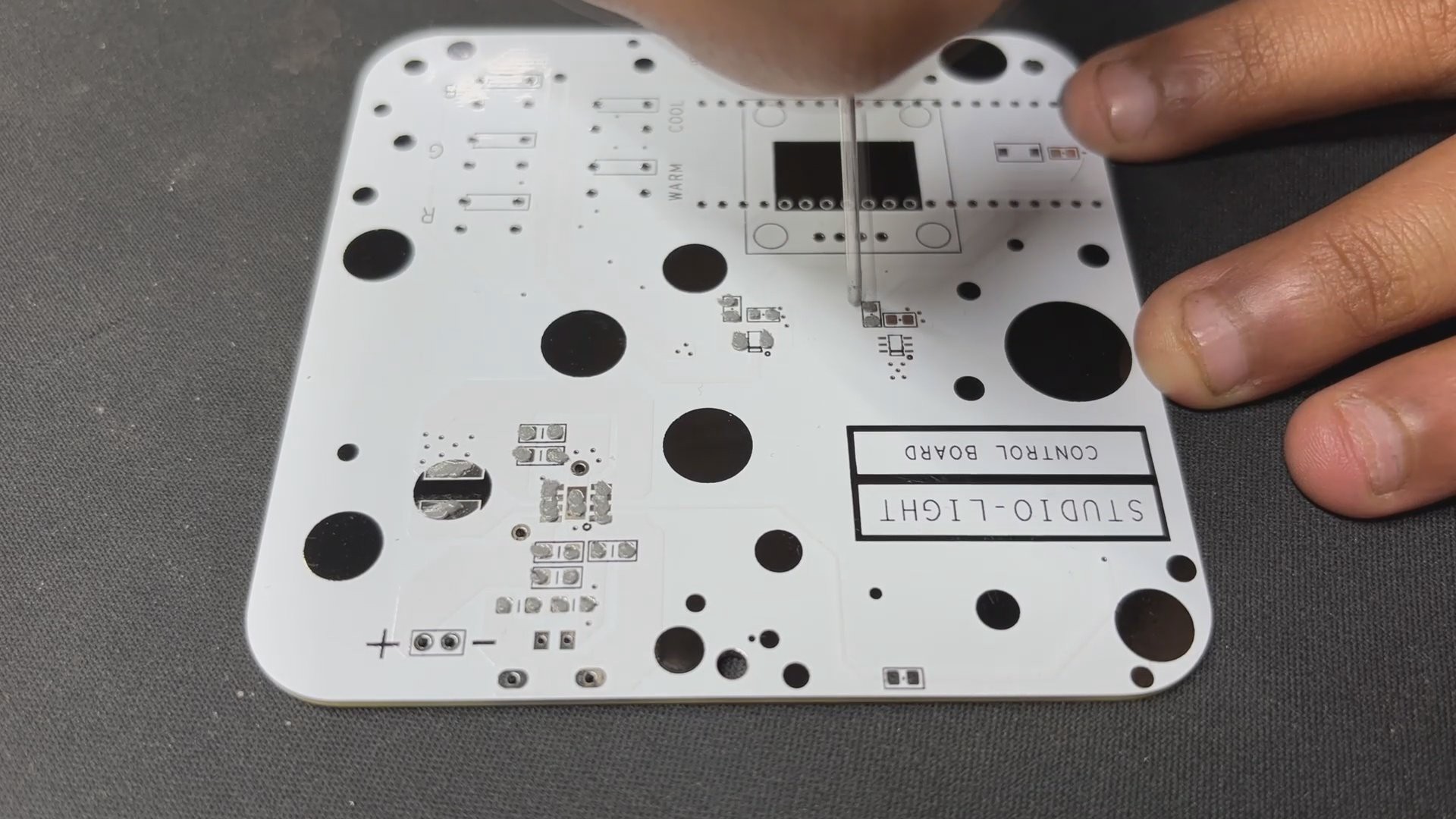
The PCB design for this project is divided into two primary boards: the LED board and the PICO driver board. Let's start by looking at the LED board.
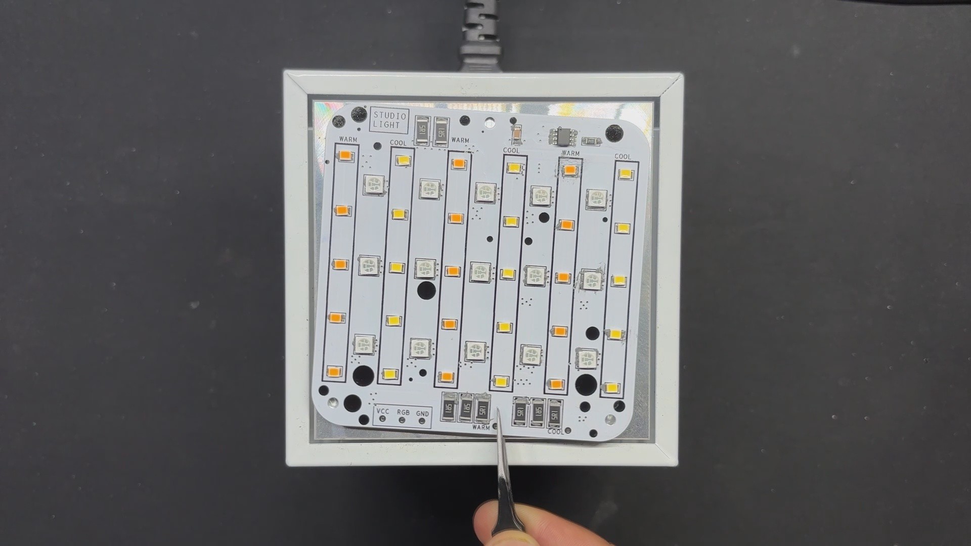
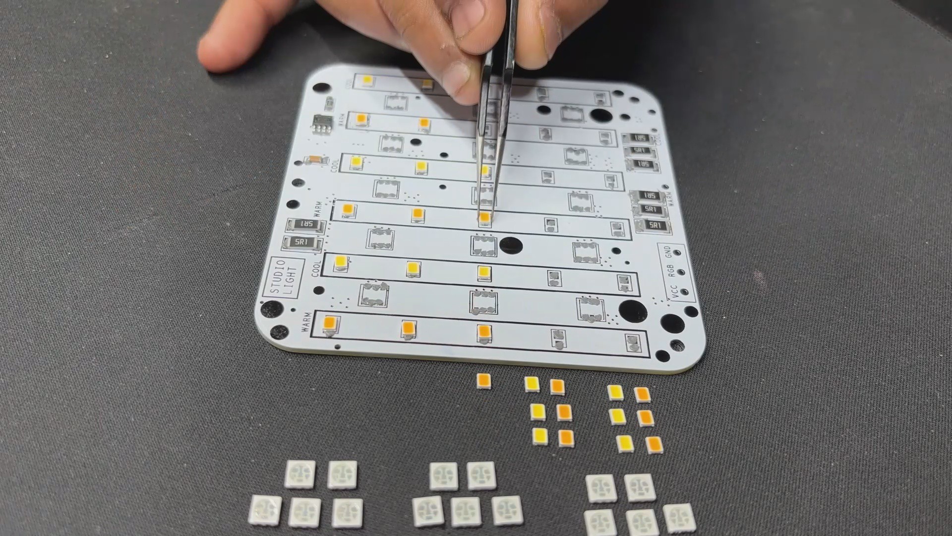
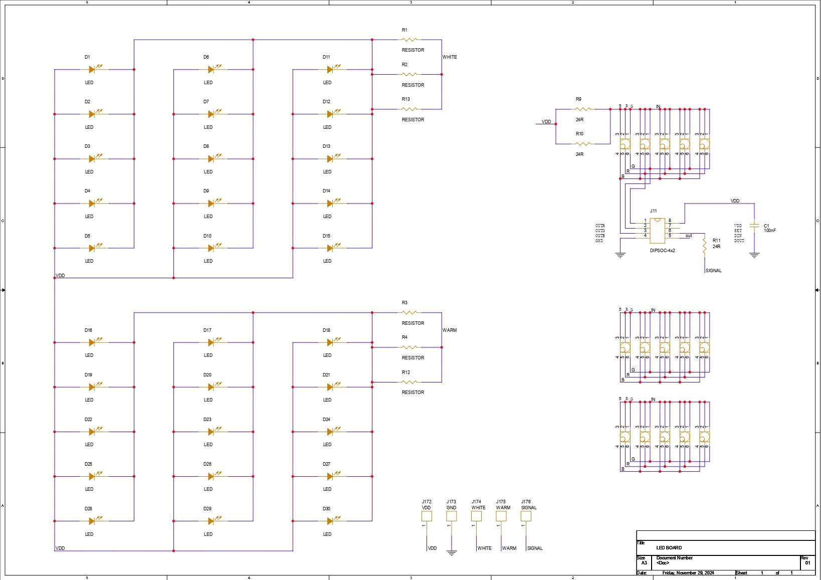
The LED board is made up of 15 Cool White LEDs, 15 Warm White LEDs, and 15 5050 RGB LEDs that are all joined together in a special way.
Let's start with the COOL WHITE LED SEGMENT, where all LEDs are linked in parallel, and the anode of each LED is connected to the board's VCC pin. The cathode is connected to three load resistors in series with a CON 1 terminal. The CON 1 terminal will be used to connect this board to the driver board.
Similarly, all Warm White LEDs are connected in parallel, with the anode linked to VCC and the cathode connected to three resistors in series via the CON 1 terminal labeled Warm.
Both warm and cool LEDs have an operating voltage of 0.2W or 3.3V and a forward current of 60mA.
In regards to RGB LEDs, we did not use addressable Neopixels, instead opting for a cheaper non-addressable 5050 RGB LED. To add smart functionality to the non-addressable LEDs, we added the WS2811 Driver circuit, which is connected to all 15 RGB LEDs and can operate all of them with a single GPIO pin.
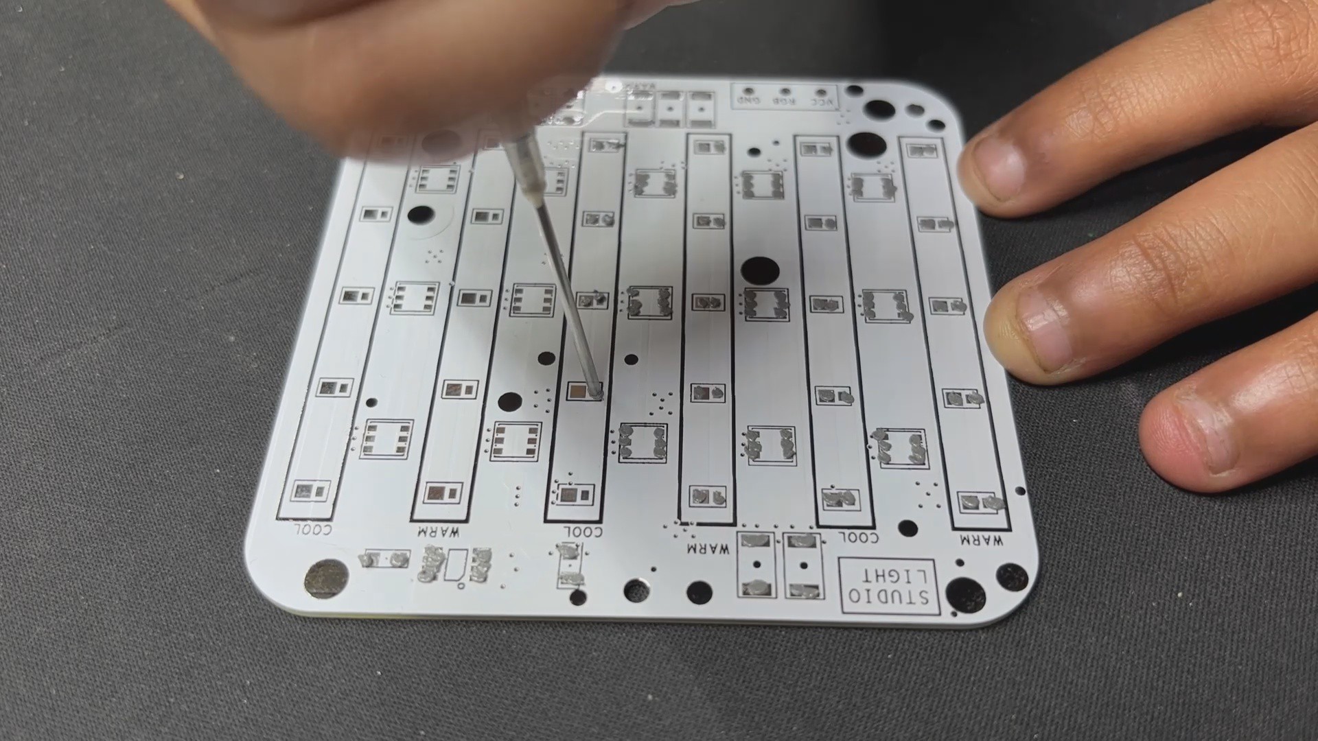
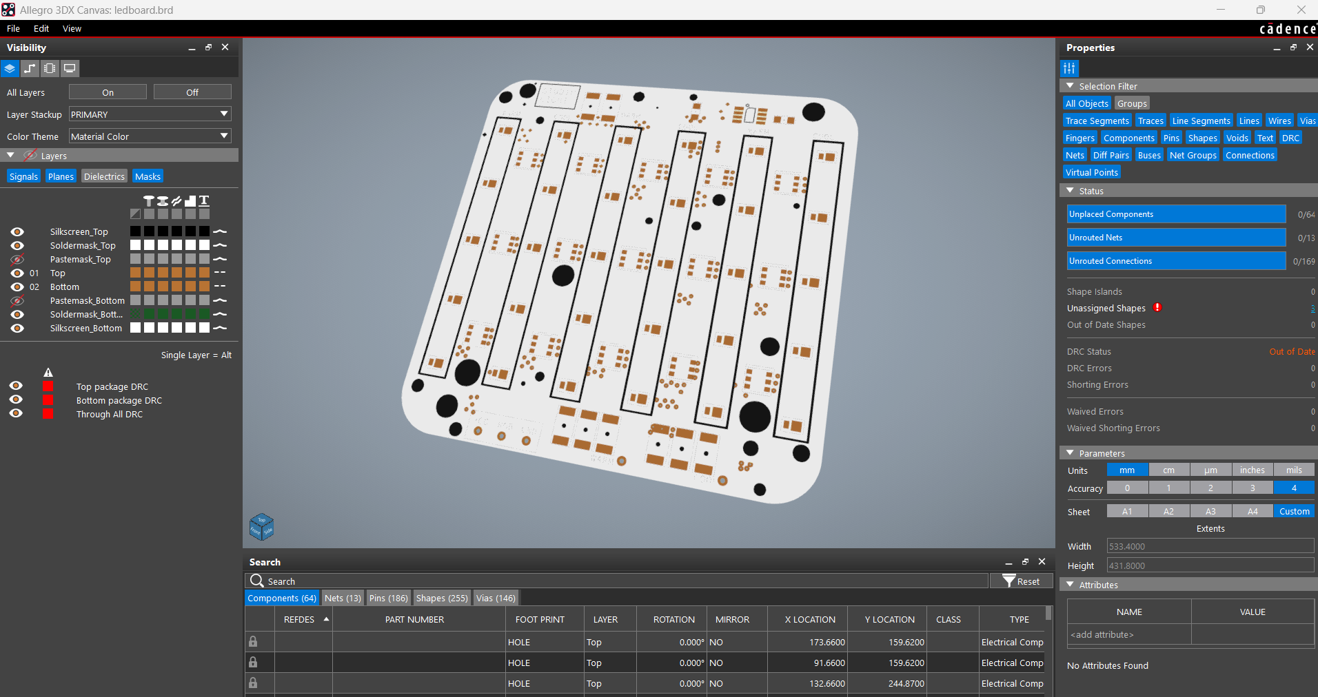
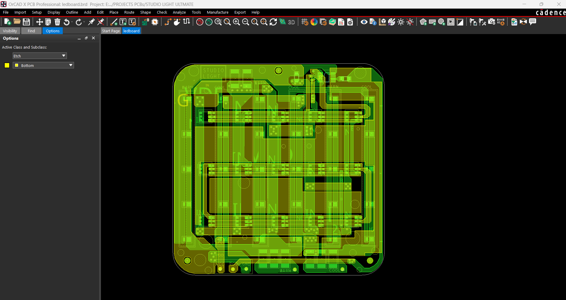
For board layout, we extracted the board outline from our cad file and used it to create the PCB design, which included the LED position, board size, and, most importantly, the mounting hole location.
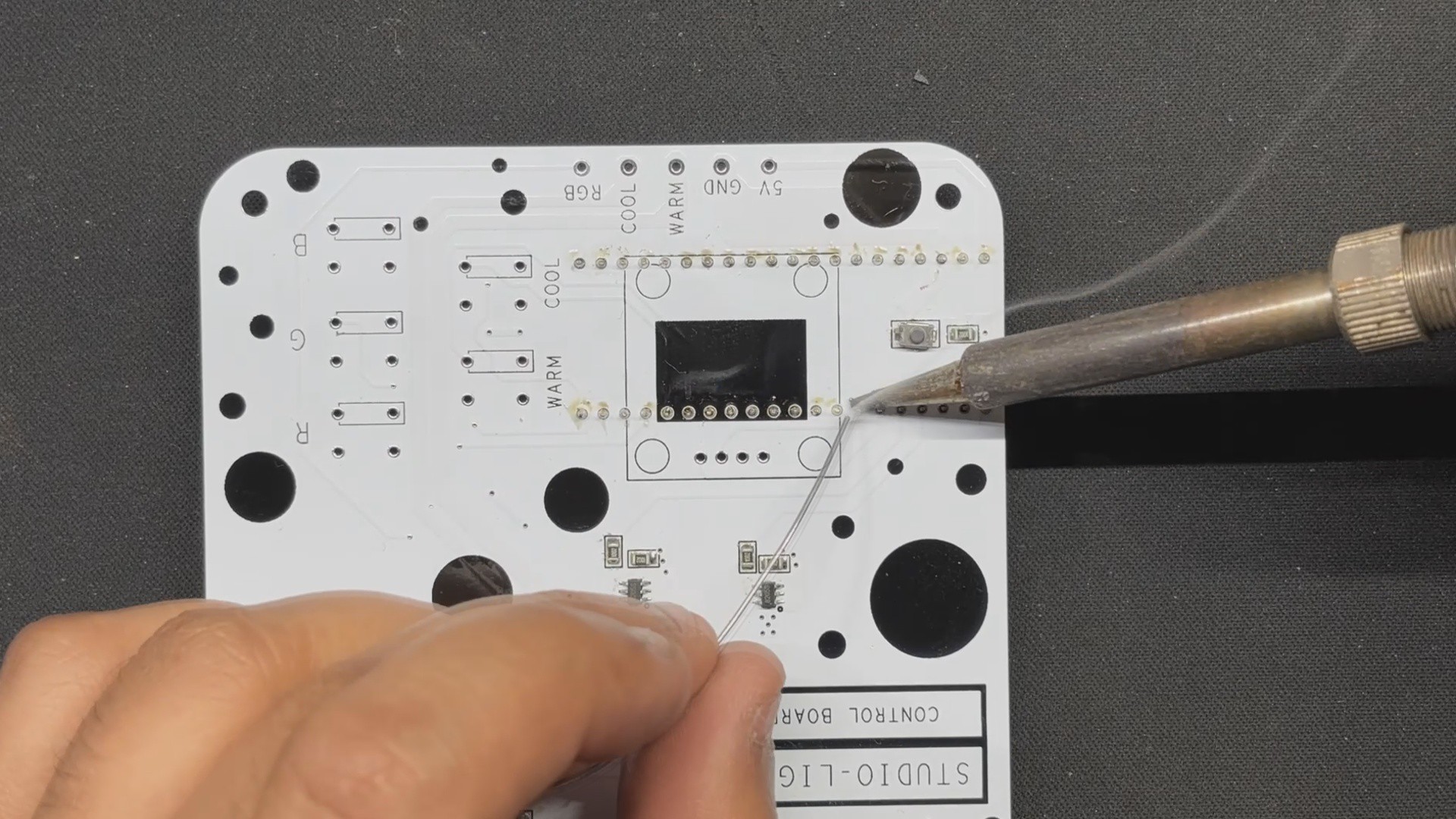
PCB DESIGN: PICO DRIVER
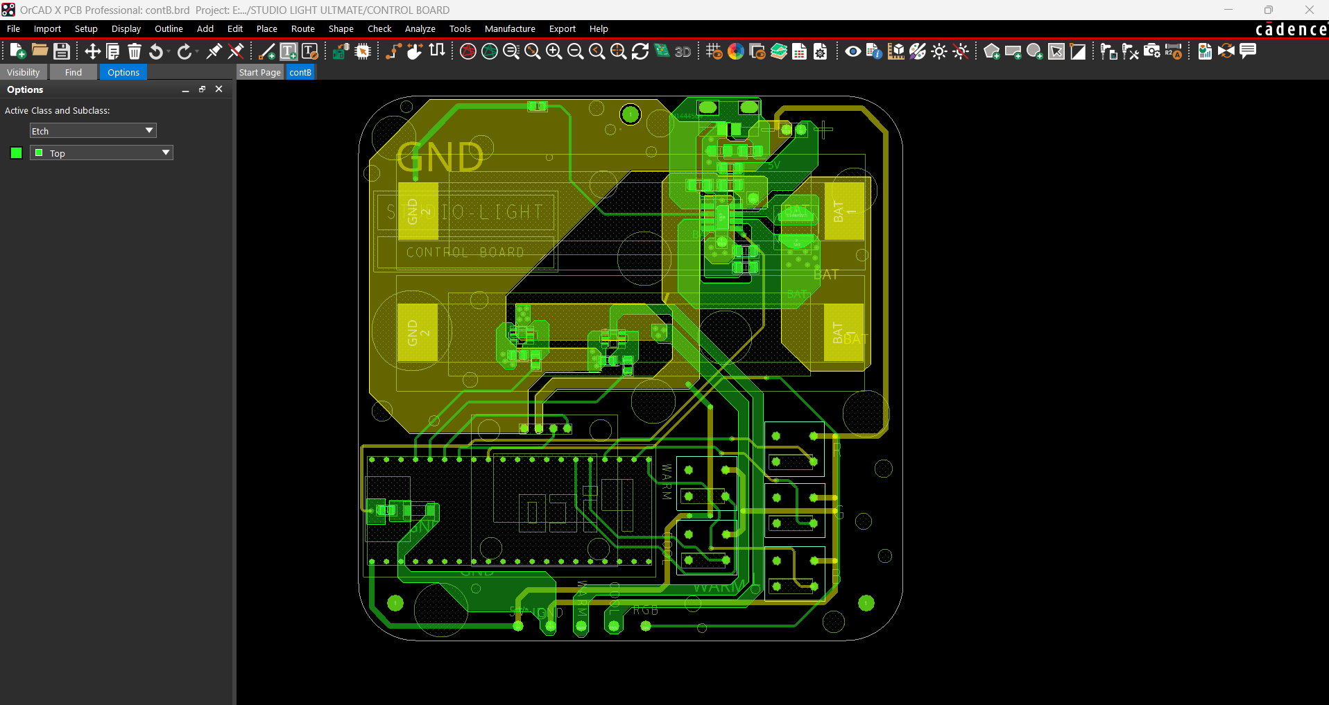
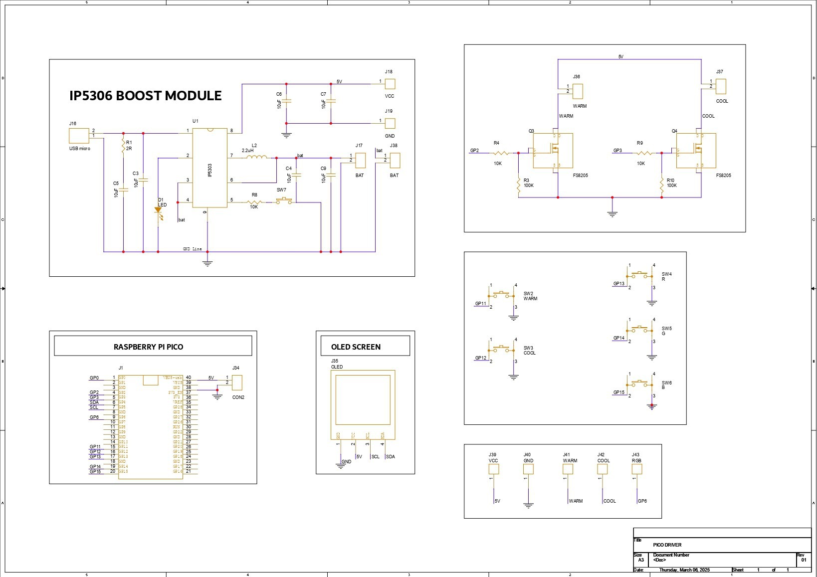
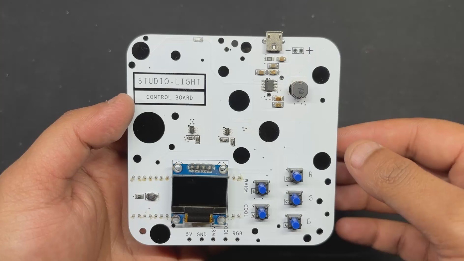
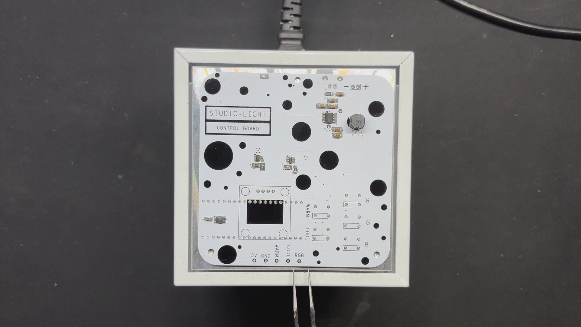
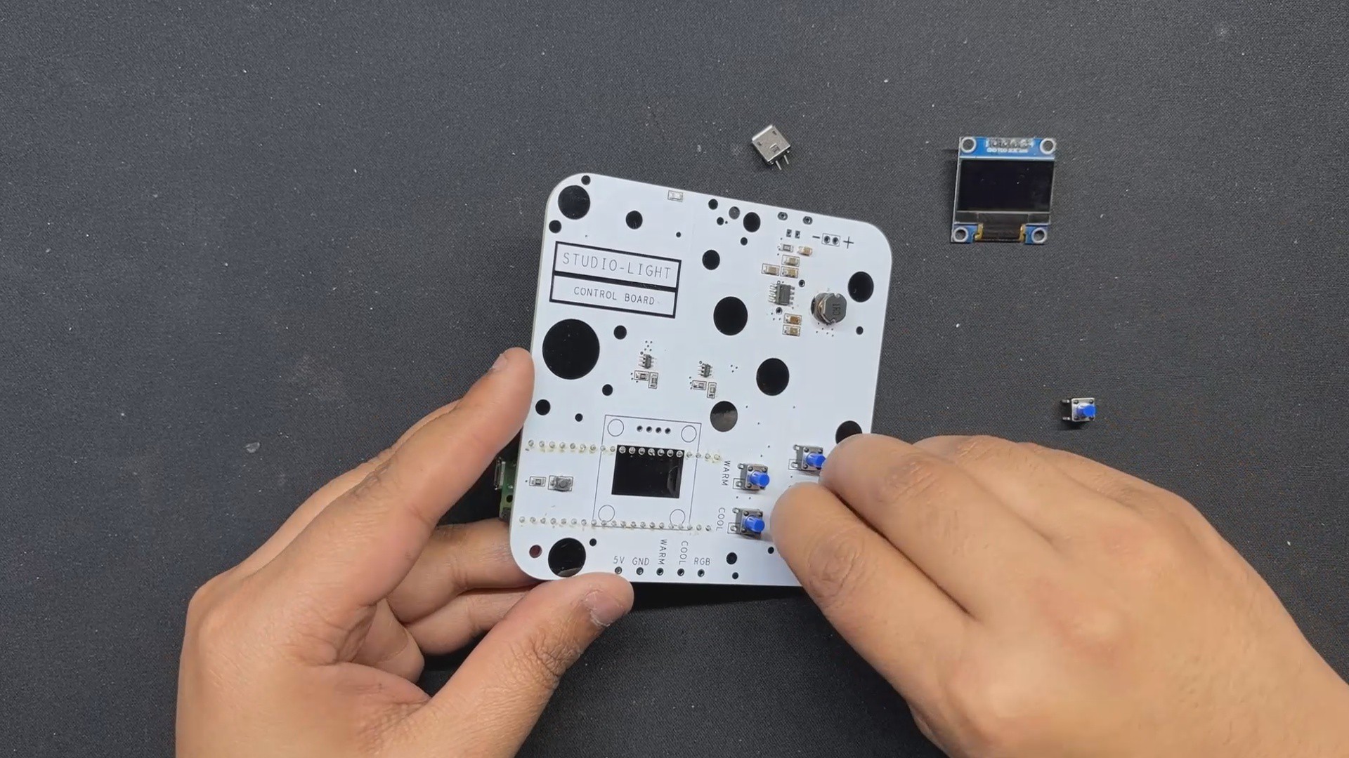
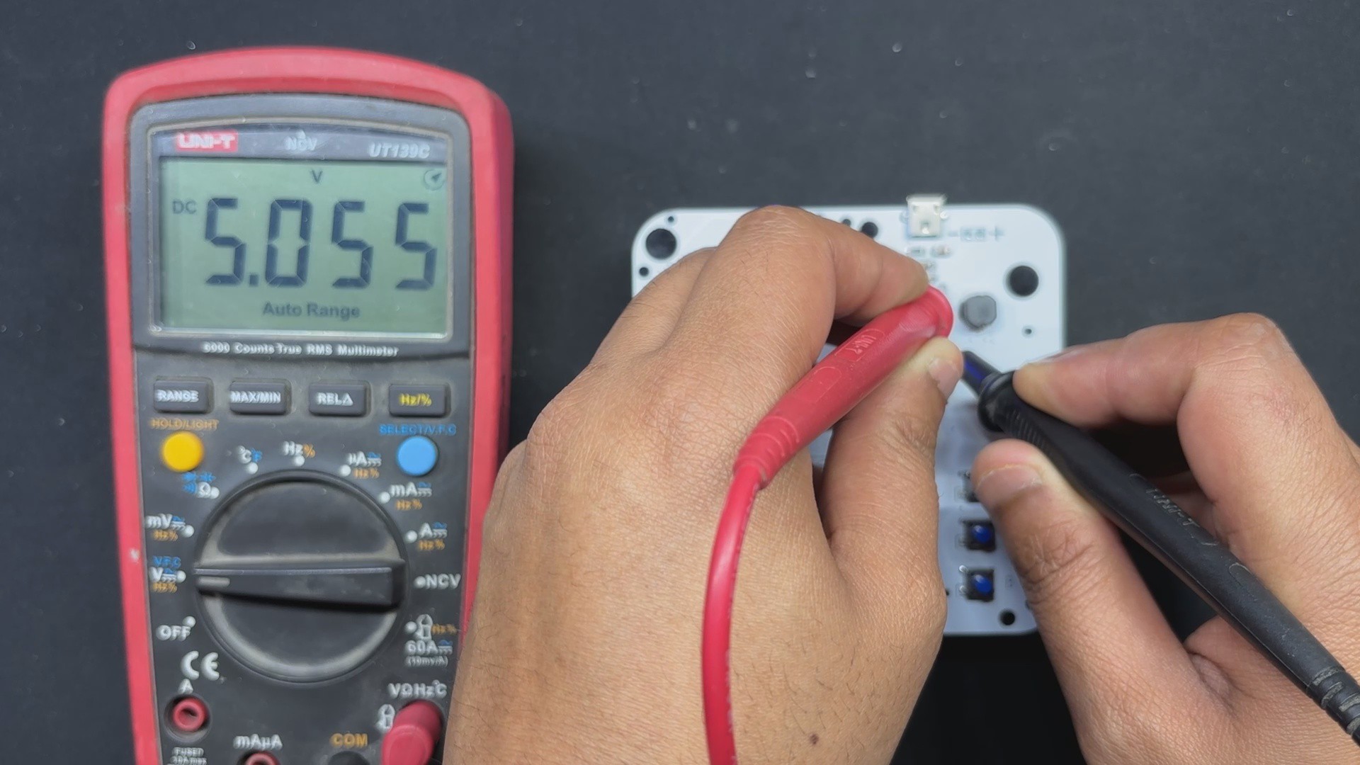
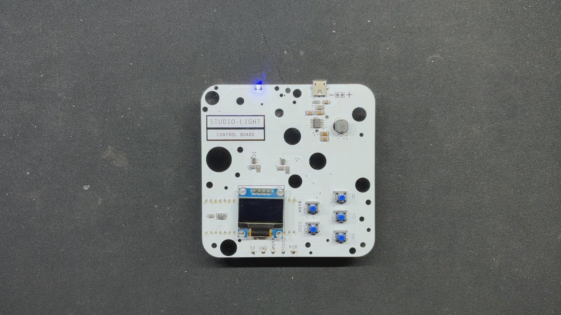
The PICO DRIVER circuit is primarily composed of three sections: the IP5306 Boost Module part, which acts as the primary power source for all of the components. The PICO Setup consists of a Raspberry Pi PICO 2 coupled to an OLED display, buttons, and a two-mosfet gate.
The third section is the Mosfet Driver, which consists of two 8205S N channel mosfet integrated circuits that will power the Warm and Cool LEDs. The LED board will be linked to the PICO Driver board via the CON 1 terminals on the board.
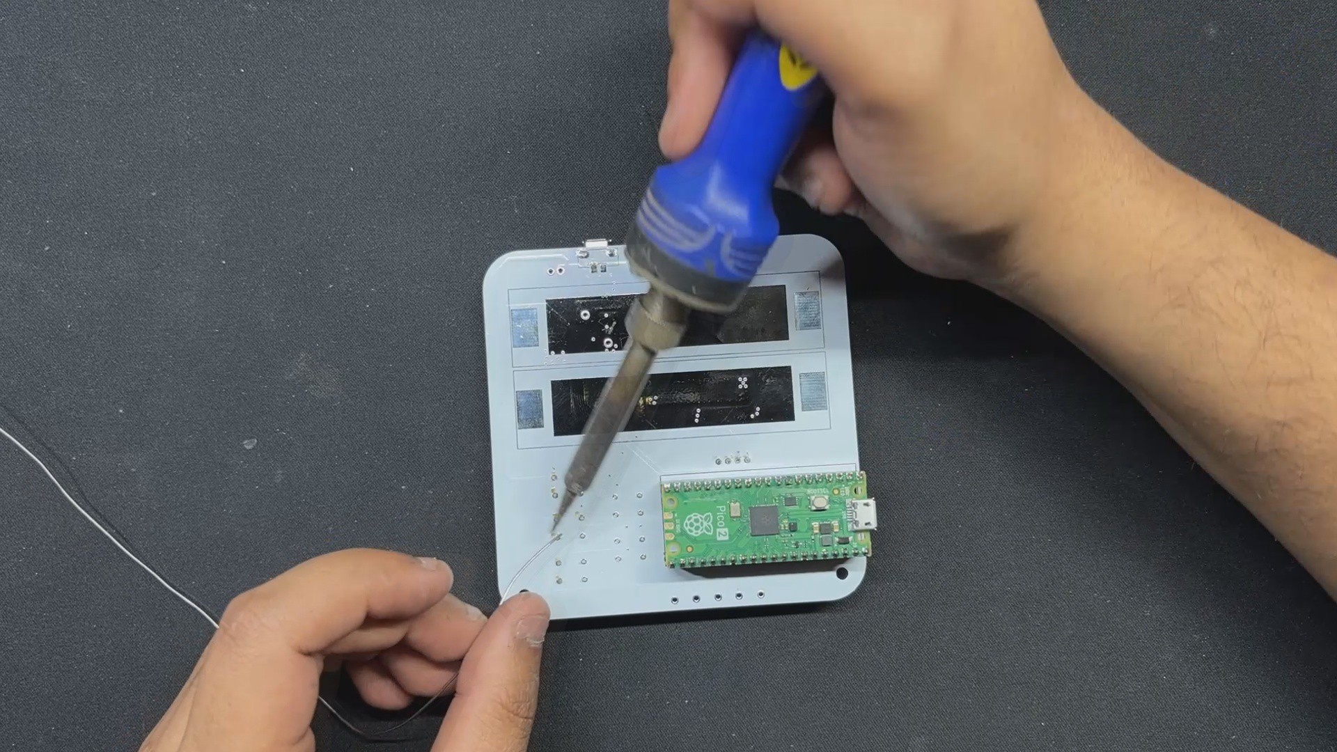
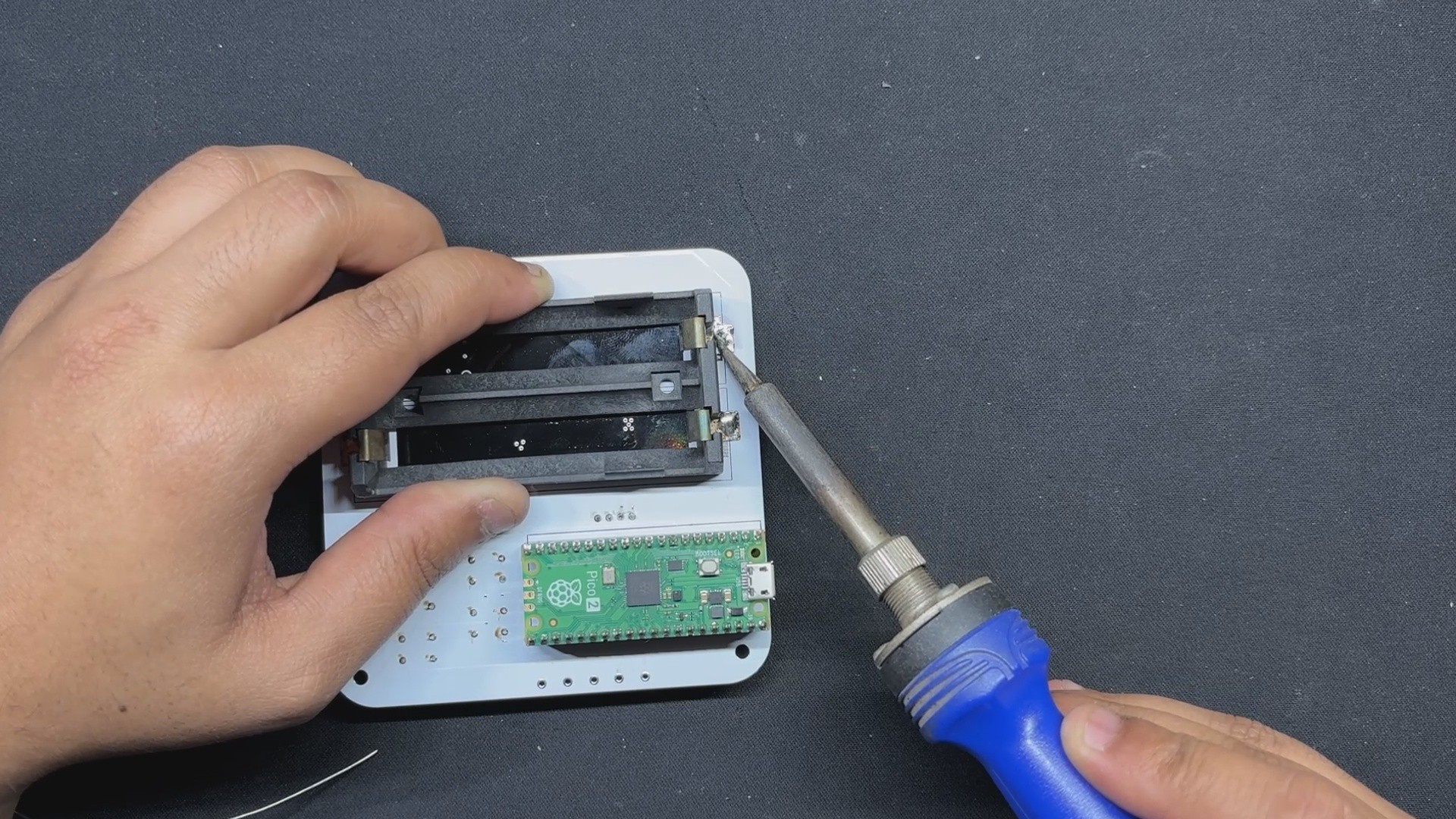
For the PCB Design, we follow the Cad file and place all of the SMD components on the top side of the board, along with buttons and an OLED display; on the bottom side of the PCB, we place the Lithium Cell Holder and PICO 2.
NextPCB PCB Service
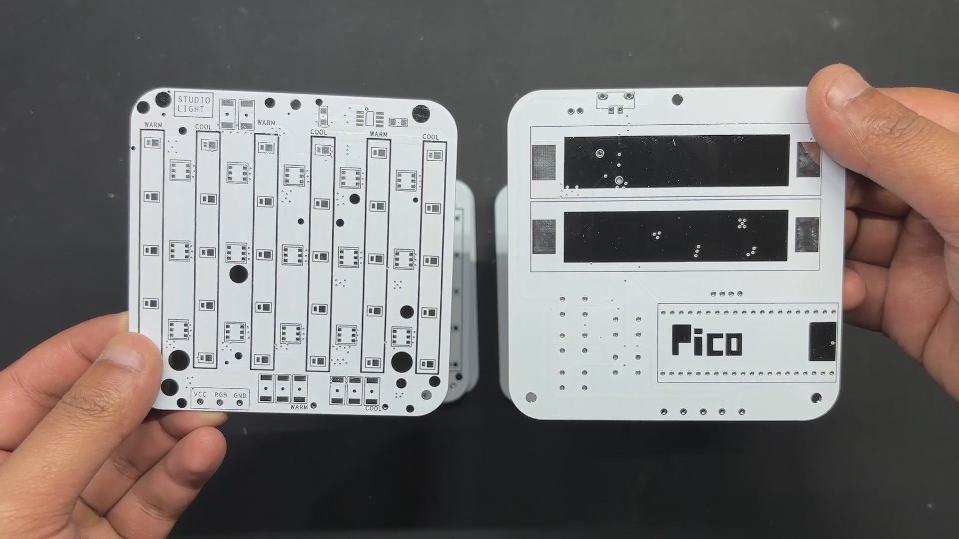
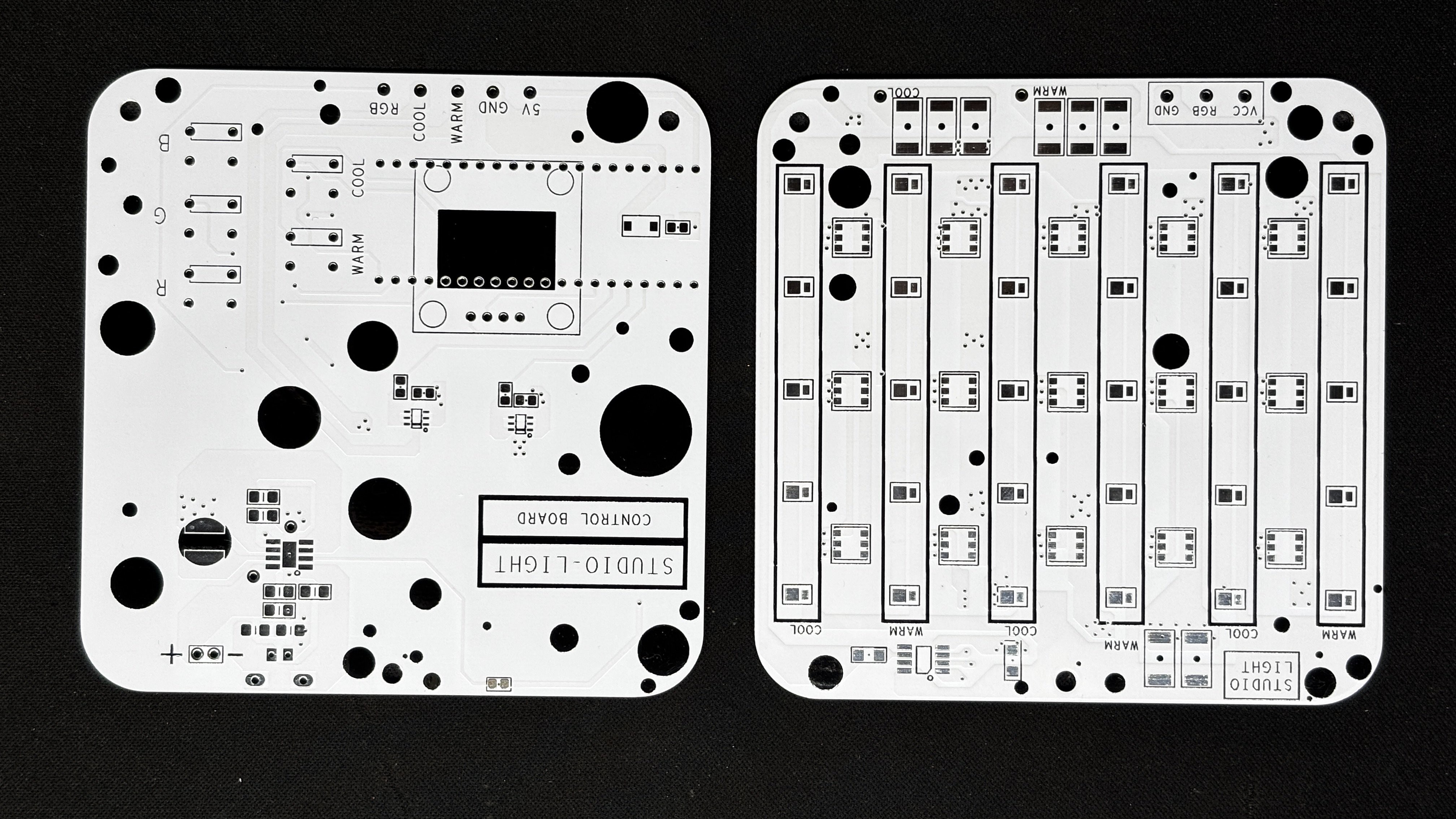
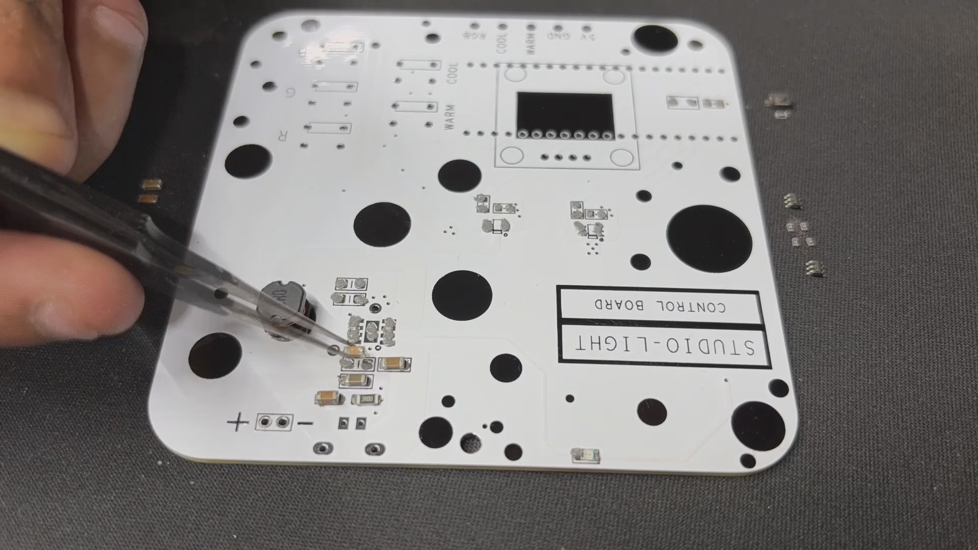
After completing both PCB designs, Gerber Data was sent to HQ NextPCB, and two orders were placed in a white soldermask with black slikscreen.
After placing the order, the PCBs were received within a week, and the PCB quality was pretty great.
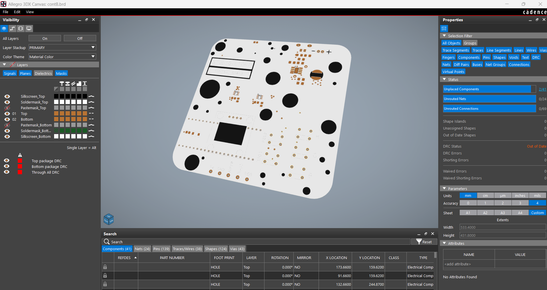
In addition, I have to bring in HQDFM to you, which helped me a lot through many projects. Huaqiu’s in-house engineers developed the free Design for Manufacturing software, HQDFM, revolutionizing how PCB designers visualize and verify their designs.
Take advantage of NextPCB's Accelerator campaign and get 2 free assembled RP2040-based PCBs for your innovative projects.
https://www.nextpcb.com/blog/rp2040-free-pcba-prototypes-nextpcb-accelerator
This offer covers all costs, including logistics, making it easier and more affordable to bring your ideas to life. SMT services can be expensive, but NextPCB is here to help you overcome that...
Read more »