 Makestreme
-
1Design and 3D print
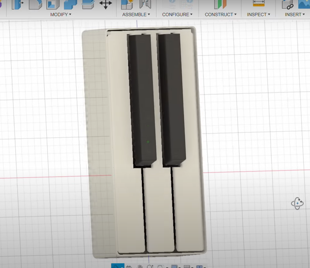
I started designing the doorbell in Fusion 360. I came across this doorbell design on Pinterest that I used as a reference. However, that design appeared to have all the keys joined together as a single button. But I wanted five distinct, individually playable keys. So my design has separate keys.
![]()
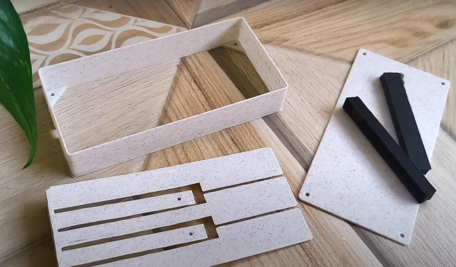
With the designs finalized, I sent them off to be 3D printed using standard PLA filament.
![]()
-
2Paint
The raw 3D-printed PLA, had a somewhat dull, grainy appearance. The white wasn’t really the piano white I was looking for.
![]()
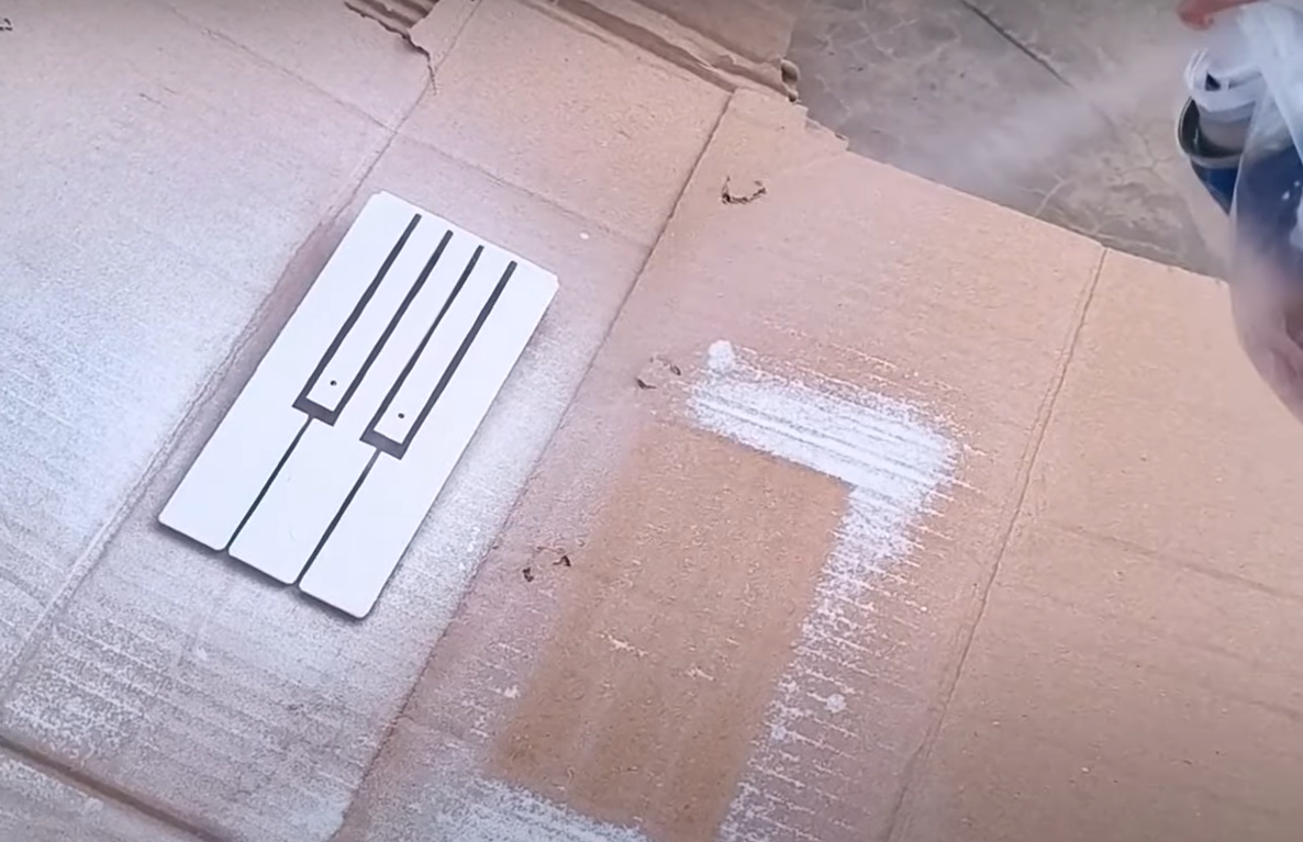
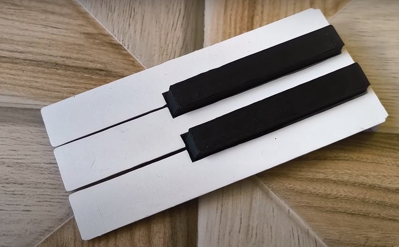
The solution to this was quite simple. A nice coat of spray paint! I opted for a glossy white spray paint to achieve a polished finish.
![]()
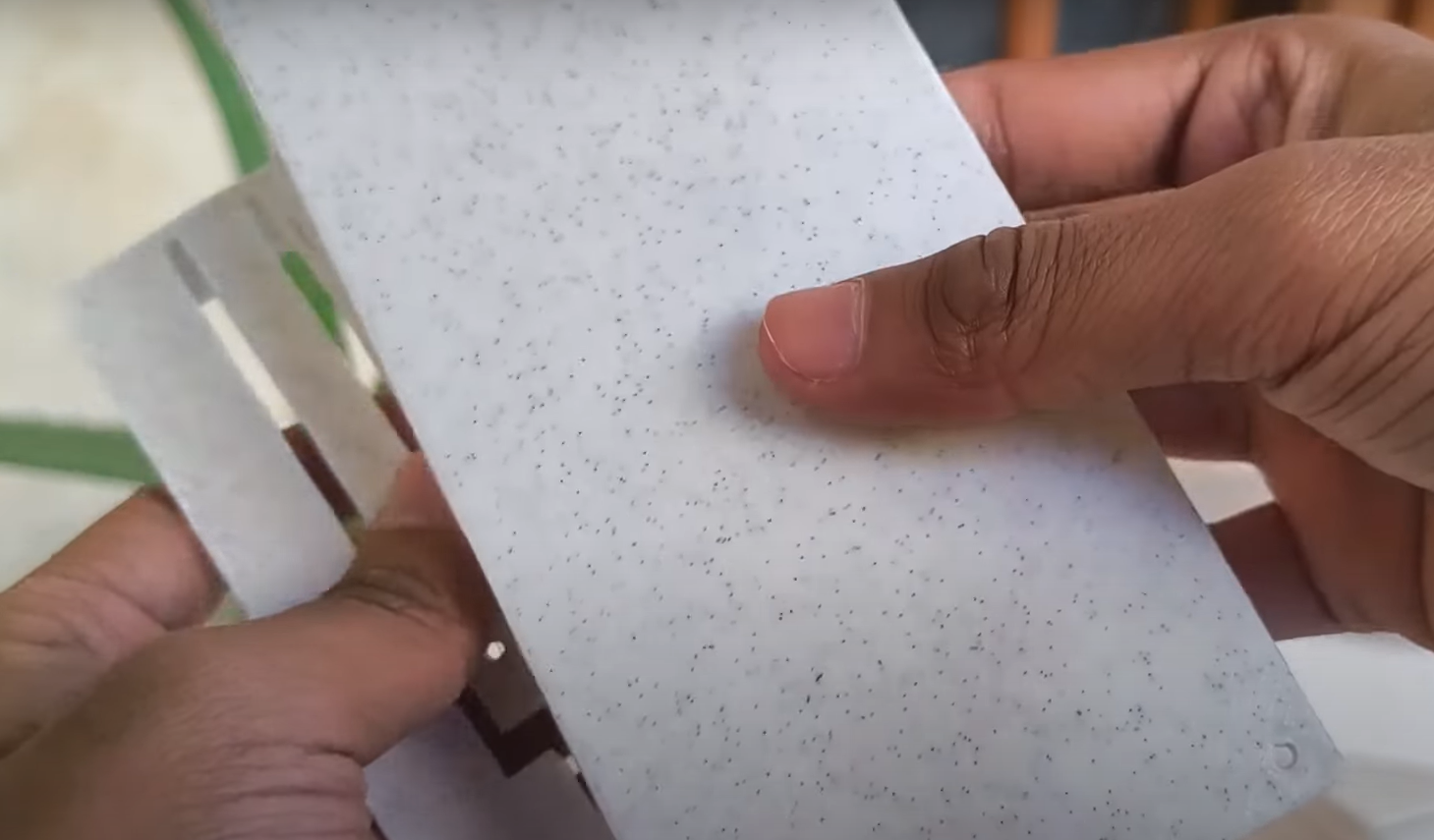
I applied three coats of the spray paint, allowing 10 to 15 minutes of drying time between each. After about 12 hours of drying, the keys looked smooth, and shiny just like a real piano.
![]()
-
3JLCMC
Part of this project was sponsored by JLCMC. If you’re a creator like me, you know how challenging it can be to find the right mechatronic parts for your projects. That’s where JLCMC comes in.
![]()
Why Choose JLCMC?
- A Name You Can Trust: Built on the strong foundation of JLC services—a global leader in PCB manufacturing and prototyping—JLCMC upholds the same dedication to quality and customer satisfaction in their mechanical parts offerings.
- Unmatched Prices: Continuing the JLC tradition, JLCMC provides mechanical parts at competitive, industry-leading prices, allowing you to stay within budget without sacrificing quality.
- Extensive Product Range: Whether you need precision-engineered components or custom solutions, JLCMC offers a comprehensive selection to support your projects—perfect for both hobbyists and professionals.
- Worldwide Reliability: With a legacy of trust from millions of makers globally, JLCMC extends the same dependable service to mechanical parts, ensuring consistent quality you can rely on.
If you sign up now, you’ll get a $19 coupon and monthly MC coupons to help save even more. Check out jlcmc.com for more!
-
4How the piano keys operate
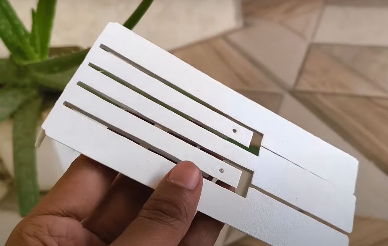
Now, let's talk about how the piano keys will work. While we could simply place push buttons underneath each key and call it a day, I wanted the keys to feel more like a real piano, with authentic key travel. For this, I decided to use some micro limit switches.
![]()
These switches offer smooth, extended travel with a satisfying soft click at the end exactly what we need for this application!
-
5Build the limit switch circuit
One challenge is dealing with the number of keys. The simplest solution would be to connect each limit switch to a separate pin on the microcontroller. However, I didn’t want to run five wires and an extra ground wire through the walls into the speaker box.
To solve this, there’s a clever trick that reduces the number of wires from six to just two.
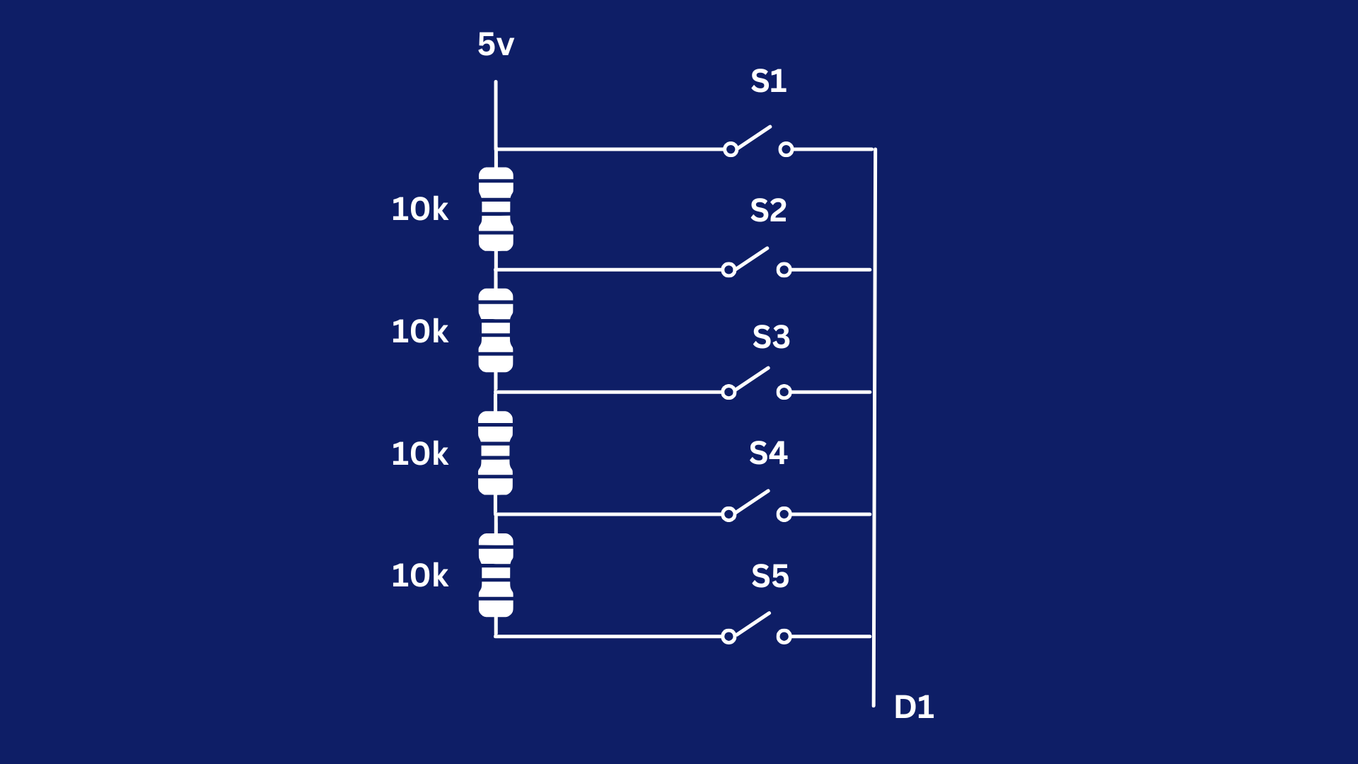
The goal is for the microcontroller to distinguish between the five switches. To achieve this, we can create a resistor ladder. The ladder is connected between 5V and a GPIO pin on the microcontroller.
![]()
When the first switch is pressed, the GPIO pin receives the full 5 volts. Pressing the second switch will cause the voltage at the GPIO pin to drop, due to the 10kΩ resistor in line. With the third switch, the voltage drop will be caused by two 10kΩ resistors in series, giving a 20kΩ resistance. The fourth switch adds 30kΩ, and the fifth switch adds 40kΩ resistance.
![]()
By reading these unique voltage drops, the microcontroller can tell exactly which switch is pressed. The only caveat is that this method won’t work if multiple switches are pressed at the same time, but that’s perfectly fine for our application.
-
6Assembling the piano side
With the piano side ready, it’s time to assemble it. First, I screwed the two black keys into place and used some glue to secure them permanently. Next, I attached the keys to the frame, again using screws and some glue.
![]()
For the circuit, I used double-sided tape to stick it to the base plate. I also soldered a long black wire, which will later connect to the speaker side.
![]()
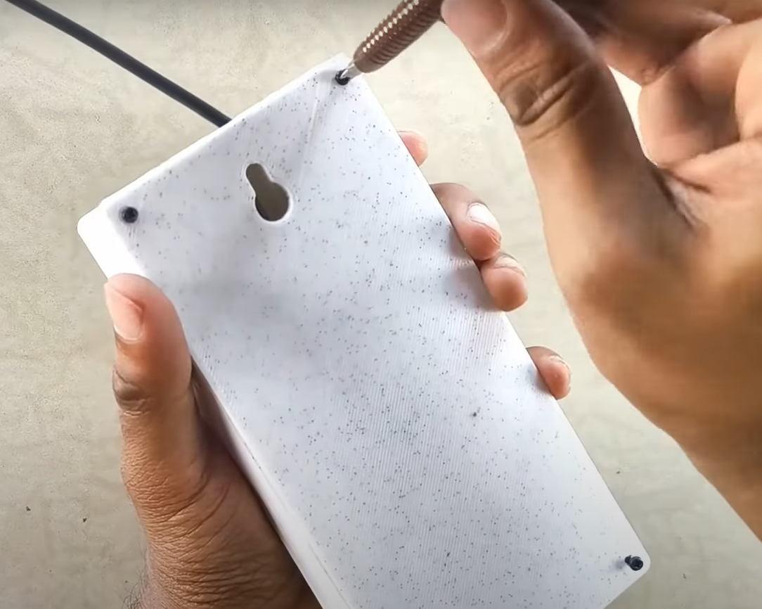
Finally, I secured the base plate to the rest of the casing.
![]()
-
7Gather data
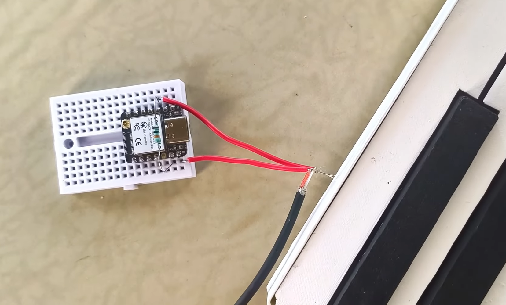
Now we need to gather some data. We've built our resistor ladder, but we need to know the specific voltage readings for each key. For this, I used a mini breadboard and plugged in the microcontroller. I added a 10 kΩ resistor between D2 and ground. Then, the two wires from the piano key assembly were connected to D2 and 5v.
![]()
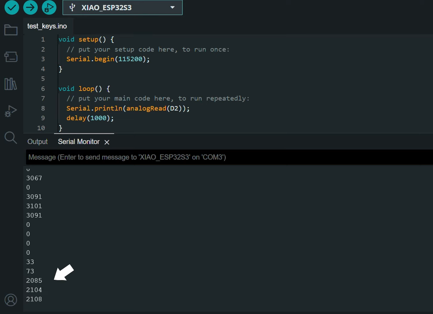
I wrote a simple program for the microcontroller. This code just reads the voltage on pin D2 and prints it to the serial monitor. We can upload this code and start pressing each key, one by one, noting the values we see. This data will be useful later, so save it somewhere.
![]()
-
8Piano sound generation
My original plan was to use a micro-SD card module for Arduino. The idea was to store recordings of individual piano tones on the SD card and then have the microcontroller play the appropriate sound file based on which key was pressed. But the SD card I wanted to use was damaged.
![]()
After exploring different methods (with the help of ChatGPT), I finally found one that delivered surprisingly decent audio quality. Now, to be honest, I don’t completely understand the code.
But, it looks like the core concept involves converting the audio files into a specific format that can be directly embedded within the microcontroller's program code. Essentially, we're turning sound into data that the microcontroller can directly 'read' and output.
I assembled the circuit on a mini breadboard. Mainly because this will allow me to upgrade it with an SD card later.
![]()
You can refer to the diagram to make your connections. But I recommend going the SD card route if you can. The sound quality will be much better.
-
9More instructions coming soon
Hackaday seems to have some problem that doesn't let me upload images. Rest of the instructions will be added as soon as the problem is resolved.
However, the full instructions are provided in the YouTube video:
A Piano Doorbell That Sounds Beautiful!
This is a beautiful looking and sounding doorbell with piano keys that will take your visitors experience to a whole new level


Discussions
Become a Hackaday.io Member
Create an account to leave a comment. Already have an account? Log In.