 Mario Ninic
This project consists of following components:
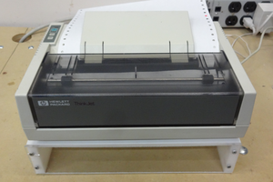
1. 3D printer (Ender from local thrift store)
2. H-field probe (from Amazon)
3. RF amplifier, Mini circuits ZKL-2 (something I have on hand in my lab)
4. Spectrum analyzer
5. Power supply for RF amp, rf cables and leads.
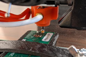
The only modification to the 3D printer was to remove extruder head assembly and to attach rf cable holding H-field probe.
I am using LabView serial interface to control printer via Marlin G code. Syntax can be found here:
https://marlinfw.org/meta/gcode/
Serial interface is also used to get cursor reading from spectrum analyzer. I did not spent much time in building this driver. The software is very simple and it could be easily implemented in Python or any other language with access to serial interface,
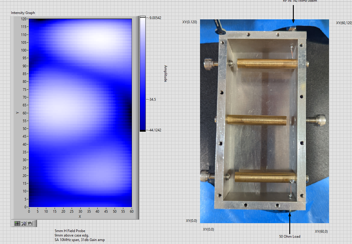
Image sample.
I made bandpass filter 1420MHz for my radio astronomy project and decided to try it on my scanner. I did open the filter cavity to run scanner probe across the top layer. This is not ideal in terms of filter performance but for this experiment this was not important. The 1420MHz signal was injected on one port and second port was terminated with 50 Ohm load. The spectrum analyzer was set to 1420MHz center frequency and peak tracking feature was turned on. Following picture is result of my scan from bottom right corner to top left corner.
Video of scanning Raspberry Pi board:
 Dan Julio
 jon.knutton
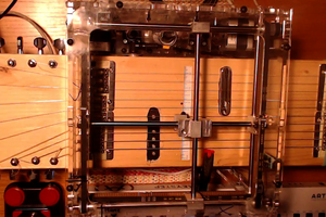
 Martijn Schouten