WJCarpenter
Since the project is a little bit iterative, details are provided in the project logs.
0%
0%
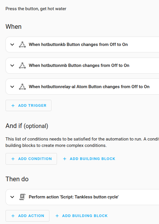
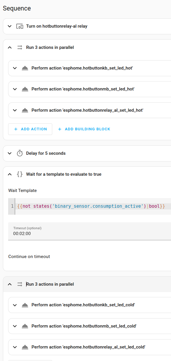
Calling for hot water, the recall
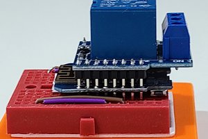
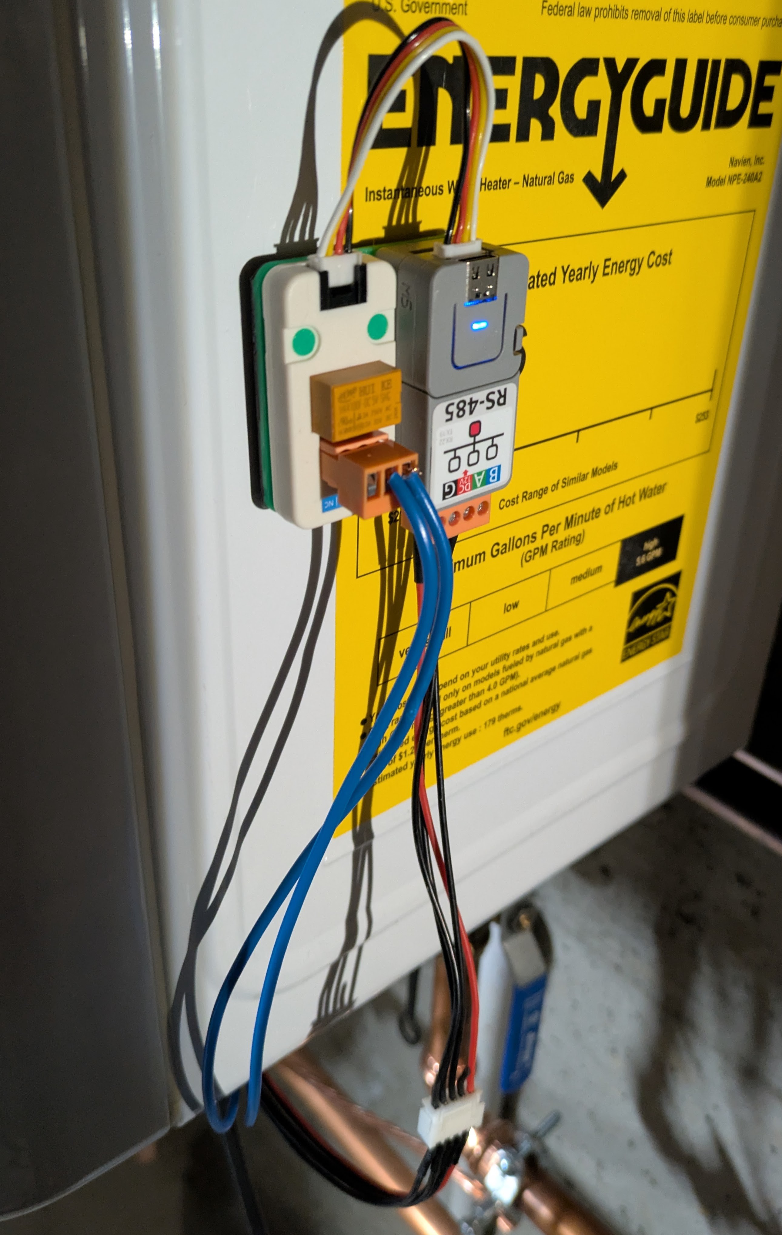
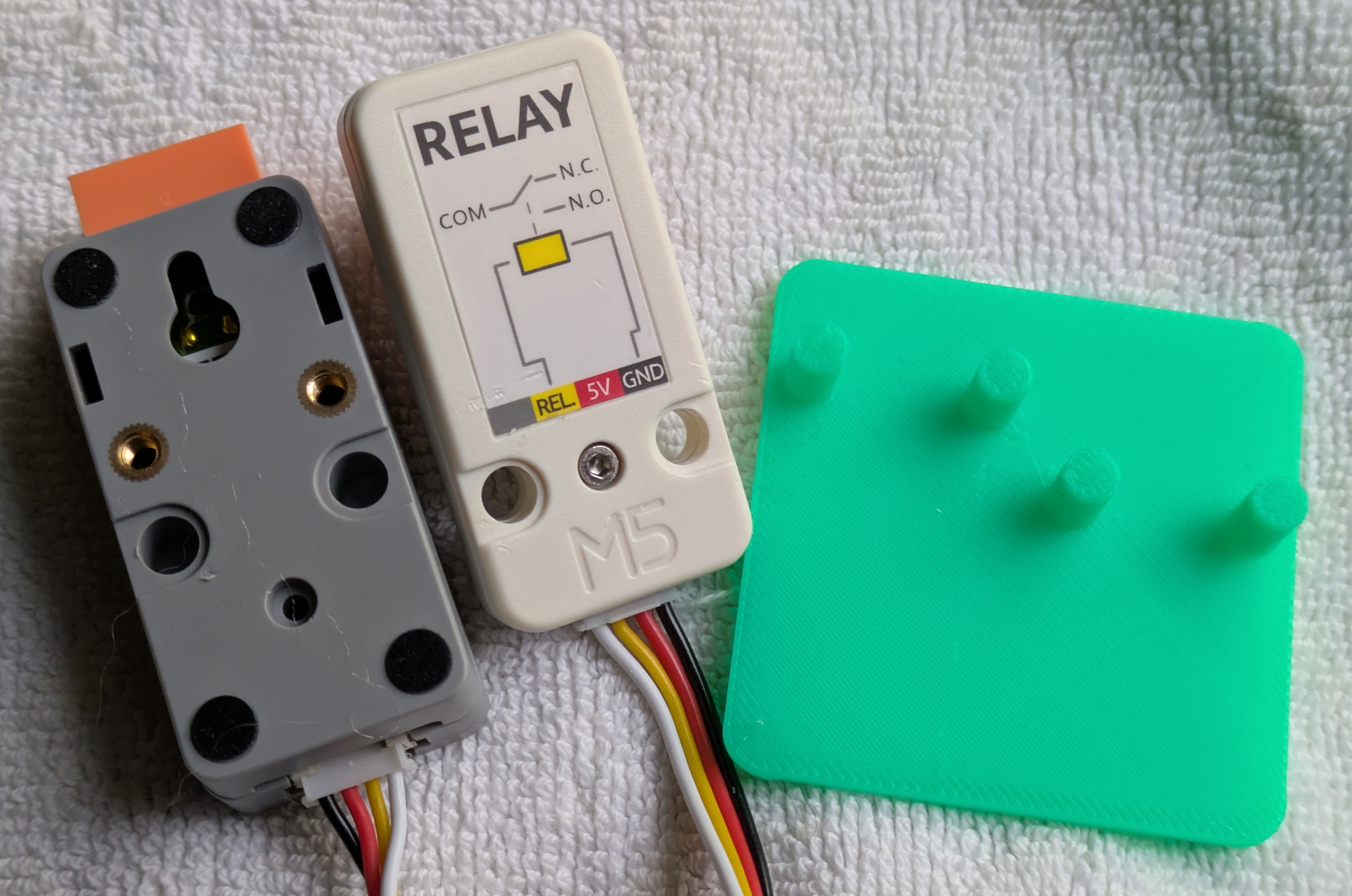
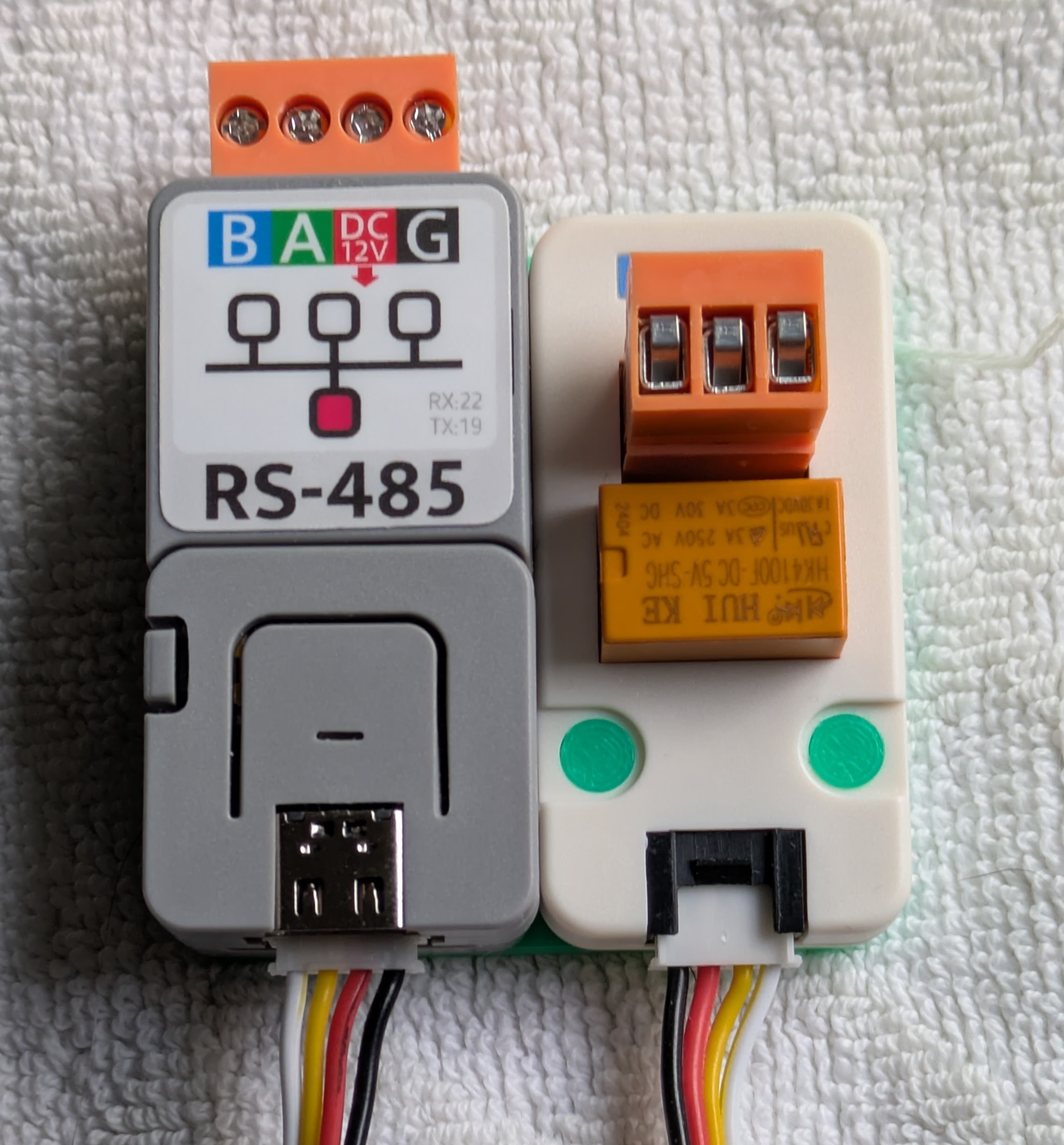
Updates and expands on my earlier project with new hardware at the water heater.
Become a Hackaday.io member
Already have an account? Log in.
Just one more thing
To make the experience fit your profile, pick a username and tell us what interests you.
Pick an awesome username
hackaday.io/
Your profile's URL: hackaday.io/username. Max 25 alphanumeric characters.
Pick a few interests
Projects that share your interests
People that share your interests


 Ben Brooks