WJCarpenter
-
Software reconfiguration, part 2
21 hours ago • 0 commentsUnless a more comprehensive Navien component for ESPHome arises, I'll stick with the pure YAML approach, which is what I'm doing right now. I started with the approach seen in https://github.com/evanjarrett/ESPHome-Navien/blob/main/navien.yaml, but I made several functional and stylistic changes. That starting YAML is great for the reverse engineering task, but it's a bit cluttered for a more refined interface.
The RSPHome UART bus component is intended to be used as plumbing by other components. In the pure YAML case, there is no other component. The UART bus debug configuration (unrelated to DEBUG logging level in ESPHome) gives direct access to the underlying I/O buffer. That is just right for extracting information and updating template sensors based on that data. Luckily, the RS485 packets for the Navien are newline-delimited, which lines up with how the UART bus debugging wants to see things.
This is the configuration part of the uart block (doesn't include the decoding logic in the lambda, which I'll describe later):
uart:
  id: uart_bus
  tx_pin: 19
  rx_pin: 22
  baud_rate: 19200
  data_bits: 8
  stop_bits: 1
  parity: NONE
  debug:
    direction: BOTH
    dummy_receiver: True
    after:
      delimiter: "\n"
    sequence:
      - lambda: |-
          UARTDebug::log_hex(direction, bytes, ' ');
          UARTDebug::log_int(direction, bytes, ' ');
When DEBUG logging is enabled in the overall configuration, all RS485 packet bytes are logged as hex and decimal values. I changed the delimiter to a space because I find that easier to read.
[10:56:54][D][uart_debug:114]: <<< F7 05 50 0F 90 2A 45 00 0B 01 0C 02 17 00 62 5D 28 00 00 00 00 05 00 00 CB 14 00 00 2C 02 E7 08 B1 50 14 00 E0 01 00 00 00 00 AA 48 00 00 00 00 58 F7 05 50 50 90 22 42 00 00 05 49 62 5D 2C 00 00 00 00 00 00 A0 BE 00 20 00 00 00 00 E0 01 01 00 00 02 B9 00 00 00 00 00 5A
[10:56:54][D][uart_debug:176]: <<< 247 5 80 15 144 42 69 0 11 1 12 2 23 0 98 93 40 0 0 0 0 5 0 0 203 20 0 0 44 2 231 8 177 80 20 0 224 1 0 0 0 0 170 72 0 0 0 0 88 247 5 80 80 144 34 66 0 0 5 73 98 93 44 0 0 0 0 0 0 160 190 0 32 0 0 0 0 224 1 1 0 0 2 185 0 0 0 0 0 9
I mainly adopted the decoding techniques and names from https://github.com/dacarson/NavienManager/blob/main/Navien.cpp, though I temporarily gave the sensors IDs and names prefixed with "dc_". For tidiness and performance reasons, I removed things that did not yet have an interpretation. Where things appeared to be booleans, I made them template binary sensors instead of template numeric sensors. For the controller and panel version information, I made them template text sensors (though they don't completely match what I see on the water heater's display). For the sensors I'm currently observing, I took them at face value, though I am pretty sure some of them are either wrongly decoded values or are misinterpreted as the wrong kind of information; that will be sorted out in a later step. For now, I am avoiding doing conversions of things like centigrade to Fahrenheit, though I do the trivial sorts of conversions needed for the Navien-specific conventions.
The structure of the code generated by ESPHome is mostly a large and sophisticated polling loop. Best practices are to avoid any long delays in a synchronously executing component. In fact, if anything takes longer than 30 ms, a warning is written to the console. I'm not sure what happens in practice, but in theory some timing-based operations could be delayed or missed. There are two sources of delay in the UART bus debugging section. First, very act of using the UART logging methods (with nothing else) is enough to bring the timing to 50-60 ms. That can be easily suppressed by setting the overall logging level to something less verbose than DEBUG. I typically use INFO for stable code. Second, the logic for decoding the bytes and publishing updates to the template sensors can add another 100 ms or so if DEBUG logging is enabled, though only about 20 ms without DEBUG logging. The decoding time is insignificant, and it's the sensor publishing that takes most of that time.
To make the UART debugging code as fast as possible, I moved all of the decoding and sensor publishing logic into separate ESPHome scripts. There are scripts for "water" packets, "gas" packets, and another for unrecognized "other" packets. Simply moving things to scripts doesn't itself accomplish anything for the timing. I configured those scripts as mode "parallel", which I think makes them run asynchronously. A nice side effect is that the water and gas scripts can be running at the same time, and the UART can also be reading the next packet at the same time. To prevent obtaining inconsistent data from the UART buffer, I copy the bytes to a dedicated buffer for each script.
I configured each to have a single running instance. I'm not sure what happens if a second instance is attempted, but I suspect it's treated the same as single mode, where there is a console message and the second instance is not run. That would mean missing some updates transmitted to Home Assistant. I had a plan for dealing with that, though I've been lazy and didn't implement it. The idea would be to check to see if the script is running and stop it before executing the new instance. That would mean that the stopped instance would only be partially through its logic. Since the bulk of the time is taken up in sensor update publishing, put all of those at the end of the script (already done), and put them in order of decreasing importance. Some sensor values are either constants or change so seldom that they are approximately constant. Those values don't go over the wire to Home Assistant very often. It would be possible to also implement logic that only did the ESPHome internal publishing periodically. That periodic update could apply for other reasons. For example, there is a figure for cumulative total gas consumption. That changes rapidly when water is being heated, but iit wouldn't make much difference if the updated total were only shown every few seconds. The "gas" packets come pretty rapid-fire when the water is actually being heated.
Here is the YAML as it currently stands:
# https://hackaday.io/project/202744-calling-for-hot-water-the-recall substitutions: node_name: hotbuttonrelay-al RELAY: 'GPIO26' LED: 'GPIO27' BUTTON: 'GPIO39' UART_TX: 'GPIO19' UART_RX: 'GPIO22' log_level: 'INFO' esphome: name: ${node_name} on_boot: then: # delay to allow other boot time stuff to settle down - delay: 5s - script.execute: set_led_cold esp32: board: m5stack-atom framework: type: arduino wifi: ssid: !secret wifi_ssid id: !secret wifi_ssid password: !secret wifi_password power_save_mode: high fast_connect: on manual_ip: static_ip: !secret hotbuttonrelay-al_ip gateway: !secret wifi_gateway subnet: !secret wifi_subnet dns1: !secret wifi_dns1 dns2: !secret wifi_dns2 logger: level: ${log_level} globals: # We use these so that we don't have to share the UART receive # buffer among scripts. - id: water_packet_bytes type: std::vector<std::uint8_t> - id: gas_packet_bytes type: std::vector<std::uint8_t> api: encryption: key: !secret hotbuttonrelay-al_apikey reboot_timeout: 60min services: - service: set_led_hot then: - logger.log: tag: 'hotbutton' level: INFO format: "service: set_led_hot" - script.execute: set_led_hot - service: set_led_cold then: - logger.log: tag: 'hotbutton' level: INFO format: "service: set_led_cold" - script.execute: set_led_cold - service: set_led_off then: - logger.log: tag: 'hotbutton' level: INFO format: "service: set_led_off" - script.execute: set_led_off ota: platform: esphome password: !secret ota_password switch: - platform: restart name: "${node_name} Reboot" - platform: gpio id: i_relay name: '${node_name} relay' pin: '${RELAY}' restore_mode: ALWAYS_OFF icon: mdi:hot-tub on_turn_on: - light.turn_on: id: bright_light red: 0% green: 100% blue: 0% - delay: 500ms - switch.turn_off: i_relay - light.turn_off: id: bright_light light: - platform: fastled_clockless id: bright_light name: ${node_name} LED chipset: SK6812 pin: '${LED}' num_leds: 1 rgb_order: GRB # required default_transition_length: 0s icon: mdi:led-on effects: - pulse: name: fast_pulse transition_length: 0.25s update_interval: 0.25s min_brightness: 20% max_brightness: 99% uart: id: uart_bus tx_pin: ${UART_TX} rx_pin: ${UART_RX} baud_rate: 19200 data_bits: 8 stop_bits: 1 parity: NONE debug: direction: BOTH dummy_receiver: True after: delimiter: "\n" sequence: - lambda: |- UARTDebug::log_hex(direction, bytes, ' '); UARTDebug::log_int(direction, bytes, ' '); if ( bytes[0] == 247 && bytes[1] == 5 && bytes[2] == 80 && bytes[3] == 80 && bytes[4] == 144 && bytes[5] == 34) { id(water_packet_bytes) = bytes; id(decode_water_packet)->execute(); } else if ( bytes[0] == 247 && bytes[1] == 5 && bytes[2] == 80 && bytes[3] == 15 && bytes[4] == 144 && bytes[5] == 42) { id(gas_packet_bytes) = bytes; id(decode_gas_packet)->execute(); } else { id(decode_other_packet)->execute(); } text_sensor: - platform: template id: dc_controller_version name: dc_controller_version - platform: template id: dc_panel_version name: dc_panel_version binary_sensor: # Local test button. This goes through the relay logic, # so it's not an analog press of the water heater button. - platform: gpio name: "${node_name} Button" id: i_button pin: number: '${BUTTON}' inverted: true mode: input: true filters: - delayed_on: 10ms - delayed_off: 10ms - platform: template id: dc_system_power name: dc_system_power - platform: template id: dc_consumption_active name: dc_consumption_active - platform: template id: dc_recirculation_running name: dc_recirculation_running - platform: template id: dc_display_metric name: dc_display_metric - platform: template id: dc_schedule_active name: dc_schedule_active - platform: template id: dc_hotbutton_active name: dc_hotbutton_active - platform: template id: dc_recirculation_active name: dc_recirculation_active sensor: - platform: template id: dc_flow_state name: dc_flow_state accuracy_decimals: 0 - platform: template id: dc_set_temp name: dc_set_temp unit_of_measurement: °C accuracy_decimals: 1 - platform: template id: dc_outlet_temp name: dc_outlet_temp unit_of_measurement: °C accuracy_decimals: 1 - platform: template id: dc_inlet_temp name: dc_inlet_temp unit_of_measurement: °C accuracy_decimals: 1 - platform: template id: dc_operating_capacity name: dc_operating_capacity accuracy_decimals: 1 - platform: template id: dc_flow_lpm name: dc_flow_lpm unit_of_measurement: LPM accuracy_decimals: 1 - platform: template id: dc_accumulated_gas_usage name: dc_accumulated_gas_usage - platform: template id: dc_current_gas_usage name: dc_current_gas_usage - platform: template id: dc_total_operating_time name: dc_total_operating_time - platform: template id: dc_accumulated_domestic_usage_cnt name: dc_accumulated_domestic_usage_cnt script: - id: set_led_hot then: - delay: 600ms # give the relay blink a chance to show - light.turn_on: id: bright_light red: 100% green: 60% blue: 0% effect: fast_pulse - id: set_led_cold then: - light.turn_on: id: bright_light color_brightness: 20% red: 0% green: 0% blue: 100% effect: none - id: set_led_off then: - light.turn_on: id: bright_light color_brightness: 0% red: 0% green: 0% blue: 0% effect: none - id: decode_water_packet mode: parallel max_runs: 1 then: - logger.log: "Navien WATER packet ^^^^" - lambda: |- std::vector<uint8_t>& bytes = id(water_packet_bytes); byte w_system_power = bytes[9]; byte w_flow_state = bytes[8]; byte w_set_temp = bytes[11]; byte w_outlet_temp = bytes[12]; byte w_inlet_temp = bytes[13]; byte w_system_status = bytes[24]; byte w_operating_capacity = bytes[17]; byte w_water_flow = bytes[18]; byte w_recirculation_enabled = bytes[33]; bool system_power = (w_system_power & 0x5) ? true : false; byte flow_state = w_flow_state; bool consumption_active = (w_flow_state & 0x20) ? true : false; bool recirculation_running = (w_flow_state & 0x08) ? true : false; float set_temp = w_set_temp/2.F; float outlet_temp = w_outlet_temp/2.F; float inlet_temp = w_inlet_temp/2.F; bool display_metric = (w_system_status & 0x8) ? true : false; bool schedule_active = (w_system_status & 0x2) ? true : false; bool hotbutton_active = (w_system_status & 0x2) ? false : true; float operating_capacity = 0.5F * w_operating_capacity; // 0.5 increments float flow_lpm = w_water_flow/10.F; bool recirculation_active = (w_recirculation_enabled & 0x2) ? true : false; id(dc_system_power).publish_state(system_power); id(dc_flow_state).publish_state(flow_state); id(dc_consumption_active).publish_state(consumption_active); id(dc_recirculation_running).publish_state(recirculation_running); id(dc_set_temp).publish_state(set_temp); id(dc_outlet_temp).publish_state(outlet_temp); id(dc_inlet_temp).publish_state(inlet_temp); id(dc_display_metric).publish_state(display_metric); id(dc_schedule_active).publish_state(schedule_active); id(dc_hotbutton_active).publish_state(hotbutton_active); id(dc_operating_capacity).publish_state(operating_capacity); id(dc_flow_lpm).publish_state(flow_lpm); id(dc_recirculation_active).publish_state(recirculation_active); - id: decode_gas_packet mode: parallel max_runs: 1 then: - logger.log: "Navien GAS packet ^^^^" - lambda: |- std::vector<uint8_t>& bytes = id(gas_packet_bytes); byte g_set_temp = bytes[14]; byte g_outlet_temp = bytes[15]; byte g_inlet_temp = bytes[16]; byte g_controller_version_lo = bytes[10]; byte g_controller_version_hi = bytes[11]; byte g_panel_version_lo = bytes[12]; byte g_panel_version_hi = bytes[13]; byte g_cumulative_gas_lo = bytes[24]; byte g_cumulative_gas_hi = bytes[25]; byte g_current_gas_lo = bytes[22]; byte g_current_gas_hi = bytes[23]; byte g_total_operating_time_lo = bytes[36]; byte g_total_operating_time_hi = bytes[37]; byte g_cumulative_domestic_usage_cnt_lo = bytes[30]; byte g_cumulative_domestic_usage_cnt_hi = bytes[31]; float set_temp = g_set_temp / 2.F; float outlet_temp = g_outlet_temp / 2.F; float inlet_temp = g_inlet_temp / 2.F; char controller_version_[20]; // some insurmountable ESPHome compile error with atof(), so report it as a string snprintf(controller_version_, sizeof(controller_version_), "%d.%d", g_controller_version_hi, g_controller_version_lo); char panel_version_[20]; snprintf(panel_version_, sizeof(panel_version_), "%d.%d", g_panel_version_hi, g_panel_version_lo); uint32_t raw_gas = (g_cumulative_gas_hi << 8 | g_cumulative_gas_lo); float accumulated_gas_usage = 0.1F * raw_gas; // Using float multiplication for better precision float current_gas_usage = g_current_gas_hi << 8 | g_current_gas_lo; // Convert total operating time to seconds using 32-bit arithmetic uint32_t raw_time = (g_total_operating_time_hi << 8 | g_total_operating_time_lo); uint32_t total_operating_time = 60 * raw_time; // Safe with uint32_t // Convert domestic usage count using 32-bit arithmetic uint32_t raw_usage = (g_cumulative_domestic_usage_cnt_hi << 8 | g_cumulative_domestic_usage_cnt_lo); uint32_t accumulated_domestic_usage_cnt = 10 * raw_usage; // Safe with uint32_t id(dc_set_temp).publish_state(set_temp); id(dc_outlet_temp).publish_state(outlet_temp); id(dc_inlet_temp).publish_state(inlet_temp); id(dc_controller_version).publish_state(controller_version_); id(dc_panel_version).publish_state(panel_version_); id(dc_accumulated_gas_usage).publish_state(accumulated_gas_usage); id(dc_current_gas_usage).publish_state(current_gas_usage); id(dc_total_operating_time).publish_state(total_operating_time); id(dc_accumulated_domestic_usage_cnt).publish_state(accumulated_domestic_usage_cnt); - id: decode_other_packet max_runs: 1 mode: parallel then: - logger.log: "Navien OTHER packet ^^^^" -
ESPHome implementation alternatives
3 days ago • 0 commentsBesides the collaborative reverse-engineering effort documented in the forum thread, there are at least 2 concrete ESPHome interface configurations. They differ a bit in approach. The github repositories for both include documentation of the packet formats. They expect bytes to be read/written over the UART interface, implying a separate component that translates the microcontroller's logic levels to RS485 signals.
The repository https://github.com/evanjarrett/ESPHome-Navien takes the approach of defining everything inside a YAML file. Debug logging within that configuration facilitates the iterative discovery process for reverse engineering. Most of the packet data bytes are made available as simple values, but some well-understood items are given semantically meaningful names. Some ideas for this repository seem to have been taken from or inspired by https://github.com/esphome-econet/esphome-econet.
The repository https://github.com/htumanyan/navien takes the approach isolating the low-level manipulation into an ESPHome custom component. That simplifies the YAML configuration and, in the long term, is more consistent with how other components are usually referenced in ESPHome. However, it comes at the expense of being a bit more cumbersome for iterative discovery. Only a handful of data items are exposed as sensors and switches for use in YAML. Adding more requires manipulating the code for the custom component and making related changes to the YAML.
There is also a non-ESPHome implementation in repository https://github.com/dacarson/NavienManager. It used Arduino environment but is still useful as an information source.
My short-term aims are these:
- Only read from the water heater; never write. That's just a safety measure. If something goes wrong, I can't be the case that I sent a command that gave the Navien brain damage. The only thing I'm really interested in commanding is the press of the Hot Button, which I am doing with the tried and true relay technique.
- I want to be able to see when the recirculation pump turns off. That will let me give better user feedback for my remote button presses.
Taking those into account and the current state of the two GitHub repositories, I plan to start with the pure YAML implementation. I'll observe for a while and then decide what to do.
-
Wires
3 days ago • 0 commentsIn the forum thread I mentioned, other people have already figured out the connectors and wiring arrangement for the Navien board's RS485 interface. For example, in this post, user aruffell provides this clear picture of a custom cable they created:

The connector in the picture is a 5-pin JST-XH, though the slightly preferred connector is JST-XHB (the "B" is for "buckle", the integrated clip that keeps the connector from coming out). Both have been reported to work without issue.
In this post, user tsquared shows the wiring with the connector inserted into the socket on the Navien board:
RS485 uses differential signalling, and there is an A and a B signal line. Only 4 pins of the JST-XHB connector are used. Combining the info from the above pictures, the pin assignments are:
- 12vdc
- B
- A
- (not connected)
- Ground
In addition to the RS485 wiring, there is also the relay wiring for the Hot Button feature. That's somewhat simpler since it's just 2 wires and orientation doesn't matter. They're connected to the relay pins Common and NO (normally open). -
Software reconfiguration, part 1
5 days ago • 0 commentsAs I mentioned, my first step is to ignore the RS485 stuff and get the hot button mechanism working with this new hardware setup. Because I used ESPHome, things are mostly abstracted. Here are the changes I made based on testing the new assembly:
- Changed the node name to "hotbuttonrelay-al" ("al" for Atom Lite) to prevent a collision with the existing hardware.
- Modify the board definition and the referenced GPIO pins for the button and the relay trigger.
- I don't have an overly convenient way to wire in the BME280 climate sensor, so I just deleted that definition along with the I2C bus. (I have plenty of temperature sensors around the house, so no biggie).
- The Atom Lite doesn't have the usual on-board LED of typical ESP8266 or ESP32 development boards. Instead, it has a more sophisticated RGB LED. I redefined that as an ESPHome RGB light object using the fastled platform. (The compilation of the fastled libraries always gives a pile of warnings, but they don't seem harmful so far.)
- The mini relay board does not have an LED for visual feedback, so I configured the Atom Light LED to turn on and off colored green with the relay activation. Since the Atom Light is the same component used for the remote hot buttons, I cloned that bit of YAML to have it use the same hot and cold lighting effects. The relay activation uses 500ms. All the other handshaking and activity happens faster than that, so I put in a 600ms delay before the hot lighting effect starts. That lets me see the brief green signal for the relay activation.
Here's the YAML so far:
# https://hackaday.io/project/202744-calling-for-hot-water-the-recall

substitutions:
  node_name: hotbuttonrelay-al
  RELAY:  'GPIO26'
  LED:    'GPIO27'
  BUTTON: 'GPIO39'
  log_level: 'DEBUG'

esphome:
  name: ${node_name}
  on_boot:
    then:
      # delay to allow other boot time stuff to settle down
      - delay: 5s
      - script.execute: set_led_cold

esp32:
  board: pico32

wifi:
  ssid:      !secret wifi_ssid
  id:        !secret wifi_ssid
  password:  !secret wifi_password
  power_save_mode: high
  fast_connect: on
  manual_ip:
    static_ip: !secret hotbuttonrelay-al_ip
    gateway:   !secret wifi_gateway
    subnet:    !secret wifi_subnet
    dns1:      !secret wifi_dns1
    dns2:      !secret wifi_dns2

logger:
   level: ${log_level}
api:
  encryption:
    key: !secret hotbuttonrelay-al_apikey
  reboot_timeout: 60min
  services:
    - service: set_led_hot
      then:
        - logger.log:
            tag: 'hotbutton'
            level: INFO
            format: "service: set_led_hot"
        - script.execute: set_led_hot
    - service: set_led_cold
      then:
        - logger.log:
            tag: 'hotbutton'
            level: INFO
            format: "service: set_led_cold"
        - script.execute: set_led_cold
    - service: set_led_off
      then:
        - logger.log:
            tag: 'hotbutton'
            level: INFO
            format: "service: set_led_off"
        - script.execute: set_led_off

ota:
  platform: esphome
  password: !secret ota_password

switch:
  - platform: restart
    name: "${node_name} Reboot"

  - platform: gpio
    id: i_relay
    name: '${node_name} relay'
    pin: '${RELAY}'
    restore_mode: ALWAYS_OFF
    icon: mdi:hot-tub
    on_turn_on:
      - light.turn_on:
          id: bright_light
          red: 0%
          green: 100%
          blue: 0%
      - delay: 500ms
      - switch.turn_off: i_relay
      - light.turn_off:
          id: bright_light

# Local test button. This goes through the relay logic,
# so it's not an analog press of the water heater button.
binary_sensor:
  - platform: gpio
    name: "${node_name} Button"
    id: i_button
    pin:
      number: '${BUTTON}'
      inverted: true
      mode:
        input: true
    filters:
      - delayed_on: 10ms
      - delayed_off: 10ms

light:
  - platform: fastled_clockless
    id: bright_light
    name: ${node_name} LED
    chipset: SK6812
    pin: '${LED}'
    num_leds: 1
    rgb_order: GRB # required
    default_transition_length: 0s
    icon: mdi:led-on
    effects:
      - pulse:
          name: fast_pulse
          transition_length: 0.25s
          update_interval: 0.25s
          min_brightness: 20%
          max_brightness: 99%

script:
  - id: set_led_hot
    then:
      - delay: 600ms  # give the relay blink a chance to show
      - light.turn_on:
          id: bright_light
          red: 100%
          green: 60%
          blue: 0%
          effect: fast_pulse

  - id: set_led_cold
    then:
      - light.turn_on:
          id: bright_light
          color_brightness: 20%
          red: 0%
          green: 0%
          blue: 100%
          effect: none

  - id: set_led_off
    then:
      - light.turn_on:
          id: bright_light
          color_brightness: 0%
          red: 0%
          green: 0%
          blue: 0%
          effect: none
A side note for you young tinkerers: The first time I uploaded the firmware, I forgot to change the configured static IP. That meant an IP address collision with the existing hardware. In short order, both devices were knocked off the air. Don't be like me!
Without physically hooking this new assembly to the water heater, I tested it by configuring it into my Home Assistant automation that glues everything together. Everywhere that I have a reference to the old equipment in the automation and script, I made a cloned reference that instead references the new equipment. That means that the automation activates both the old and new relays. I can hear the tiny click when the new relay is activated.
-
Physical assembly
5 days ago • 0 commentsThe RS485 unit and the relay unit both have LEGO-compatible holes in their bodies. I decided to make a 3D-printed slab with a few LEGO studs in the right places to take advantage of that. I started with this nice custom LEGO component generating script: https://github.com/cfinke/LEGO.scad. My requirement was a little unusual, so I made a couple of local modifications to that OpenSCAD script.
- The standard height for a LEGO stud in that script is 1.8mm. I wanted them taller to give a more snug fit, so I changed that to 8.0mm. That's no good for normal LEGO stacking, but it works great with the M5stack stuff.
- I change the code a bit to suppress the generation of the studs except in the four locations where I wanted them. I spent a little time trying to see if I could parameterize that, but OpenSCAD makes that at best kind of klunky and hacky. If I later figure out a reasonably elegant way to do that, I'll send a PR to the author.
The script does include a parametric scaling factor for the diameter size of the studs. Through trial and error, I settled on 1.01 (ie, 101%) to allow for filament shrinkage and still have a snug fit.
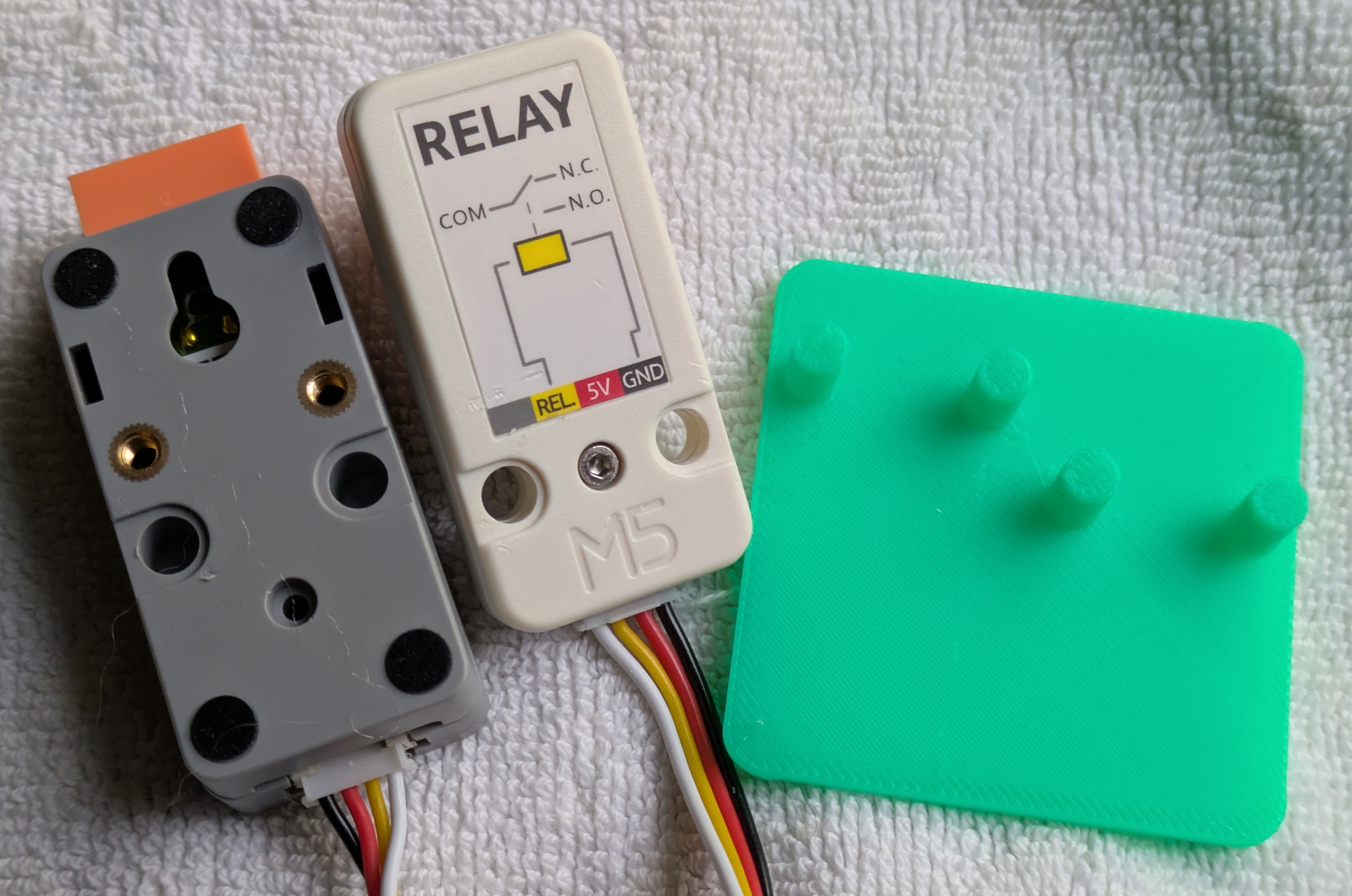
Here are the bottom sides of the components along with the 6x6 base I created.
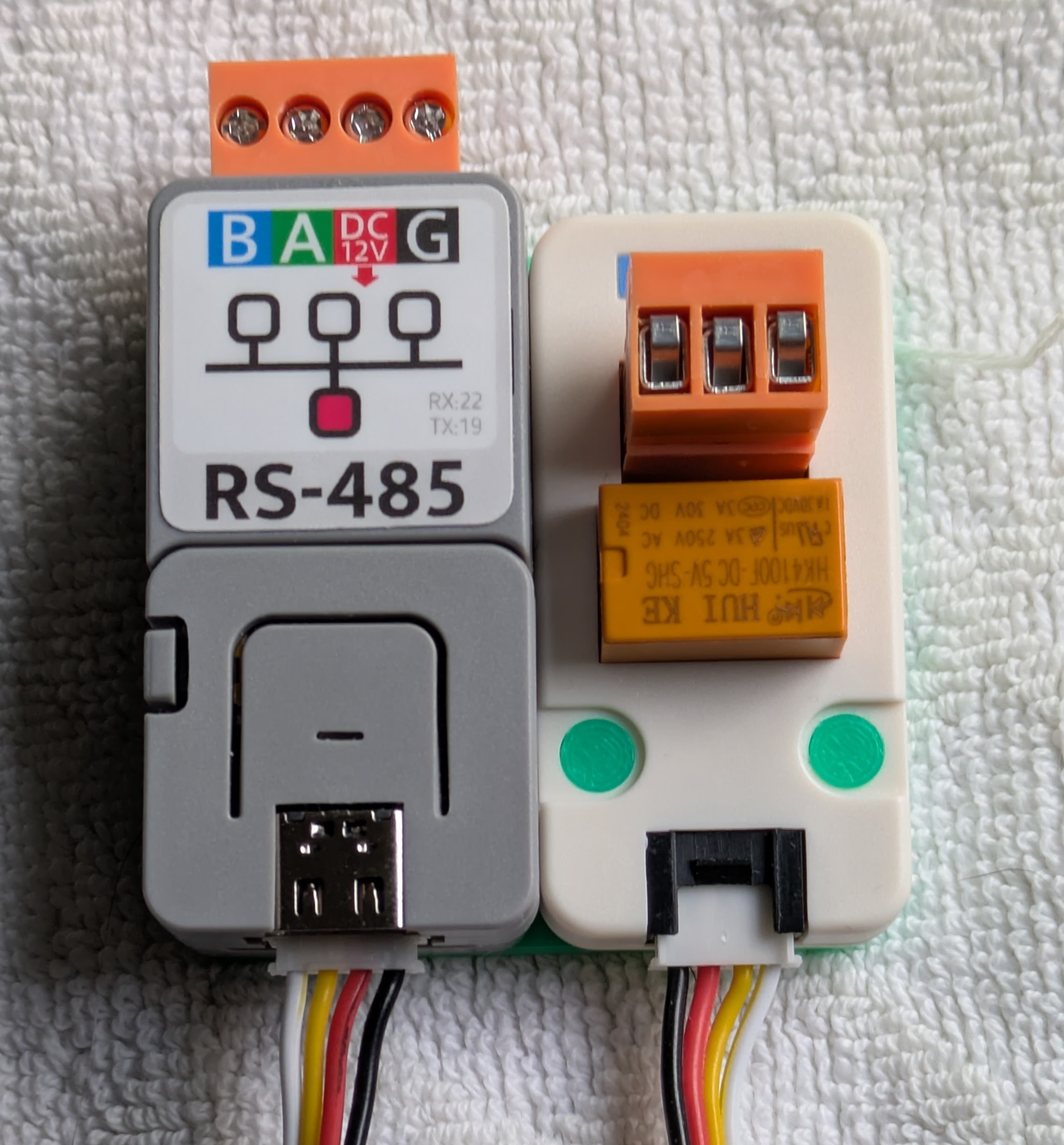
And here is what it looks like when it's press-fit together:
I think it makes a pretty tidy bundle. I haven't yet decided how I will mount this bundle to the water heater, but I'll probably use the refrigerator magnet technology I tried before. This bundle is a bit lighter than the bundle from the earlier project.
-
Hardware decisions
5 days ago • 0 commentsAt the water heater end, requirements are minimal. Just about any ESP32 variant would fit the bill. I decided to use something from their Atom series since they are cheap and I already have some on hand. Specifically, I'll use an Atom Lite, which has two physical buttons and a single RGB LED.
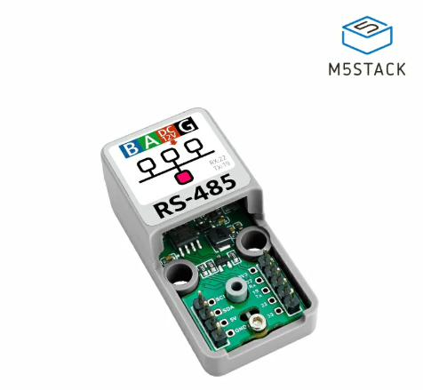
They have a couple different RS485 interface components that will work with the Atom series. The cheapest option is their RS485 to TTL Converter Unit.
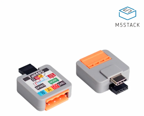
For a tiny amount more, their ATOM Tail485 - RS485 Converter for ATOM makes for a tidier package since it plugs directly into the Atom Lite.
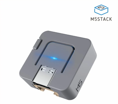
In the end, I didn't choose either of those. I spent a few bucks more and chose the ATOMIC RS485 Base.
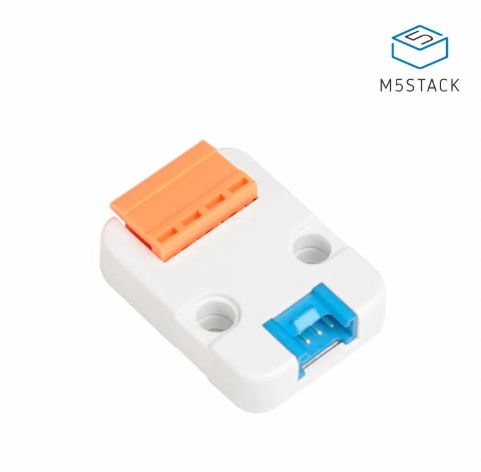
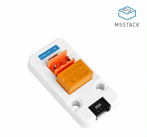
The reason for that choice is because it leaves the 4-pin port on the Atom Lite exposed. (It also leaves the USB-C port exposed for power, though once it's wired up to an RS485 circuit, that circuit can power everything.) I'm not sure if the reverse-engineered RS485 conversation will let me remotely "push the button" to call for hot water. For insurance, my first step will be to implement the hot button feature using a relay, as in the previous project. This Mini 3A Relay Unit interfaces to the Atom Lite via that 4-pin port.
The total cost for these three components is under US$20, which is not too bad for a one-off project.
-
Project motivation
5 days ago • 0 commentsMy original project has been operating for a while in a satisfactory way. I do still have one unsolved problem (knowing when the pump stops pumping), though for a while I've had some ideas about how to tackle that. In the meanwhile, some clever and industrious people over in the Home Assistant forums have been making progress on reverse engineering the wire protocol between Navien's NaviLink unit and the tankless water heater. I think that will give me the answer about the pump (not sure). To find out, I'll need an RS485 interface to the water heater control board.
If you look around for an RS485 interface board (as some of the folks in that forum thread have done), you come across some components from M5stack. Their stuff is particularly appealing for one-off projects since it mostly comes in reasonably attractive packages. I already have a little box full of assorted M5stack stuff, so I decided to make use of that and a few things I had to order from them to re-implement the hardware.
Calling for hot water, the recall
Updates and expands on my earlier project with new hardware at the water heater.