 WJCarpenter
Someone in the forum thread who owns a NaviLink unit was able to identify the connector needed for the RS485 interface. It's 5-pin JST-XHB or JST-XH. The "B" stands for buckle and is the little plastic piece that holds the connector firmly in place. For this particular equipment, the XH without a buckle holds pretty firmly. Someone also identified a source for the connectors with long pigtail wires for the 5 pins. They are readily available in lengths up to 30 cm.
That's the good news. I got some of those connectors with pigtails. I got the 30 cm length because I could always trim off some excess wire for tidiness. There are two bits of bad news. First, since I wanted to mount my device on the outside of the cabinet, I'd need to feed the cable through the knock-out grommet in the water heater case. That turns out to be about 40 cm from the socket on the control board where the cable plugs in. Second, the conductors inside the pigtail wires are pretty flimsy. It was really fiddly getting them stripped and then willing to stay in place in the screw-down terminals of the RS485 device.
I was able to get things assembled, which at least let me prove that the 12v power supply and the signals on the RS485 interface were as expected. I had to mount my device on the bottom of the cabinet, with wires hanging out and held in place by the cabinet cover weatherstripping. Yikes, like a barbarian!
Another common use for JST-XH connectors is in battery chargers for remote-controlled cars and other devices. There, the cables are called "balance cables" because of the way they work with mulit-cell lithium ion battery packs. As a trap for the unwary, the nomenclature of those cables uses a number that is one less than the number of conductors. So, for a 5-pin cable, it's called "4S". It's typically a single red wire and all the rest are black.
Balance cables are also readily available, but again in relatively short lengths. I didn't find any longer than the 30 cm cable I already had. But you can also buy cables that act as extensions, with a male connector on one end and a female connector on the other end. I bought a few of those in 20 cm length and strung them together to make an 80 cm cable. (When using these for charging batteries, there would very well be some rules about how long they can be, how many you can string together, etc. I don't think any of that applies for RS485 since it's intended to stretch over distances in noisy environments.) On the end toward the relay device, it was pretty easy to pull the connector off, leaving the metal pins that were already attached to the individual wires. Those made much better connections to the screw-down terminals of the relay, so I dropped my original pigtail cable out of the picture entirely.
Here is the final, mounted device. The Atom Lite on the RS485 base is on the right, and the relay is on the left. They are connected with a Grove connector cable (the shortest I had on hand). The device is mounted with some rare-earth magnets that I glued to the bottom.
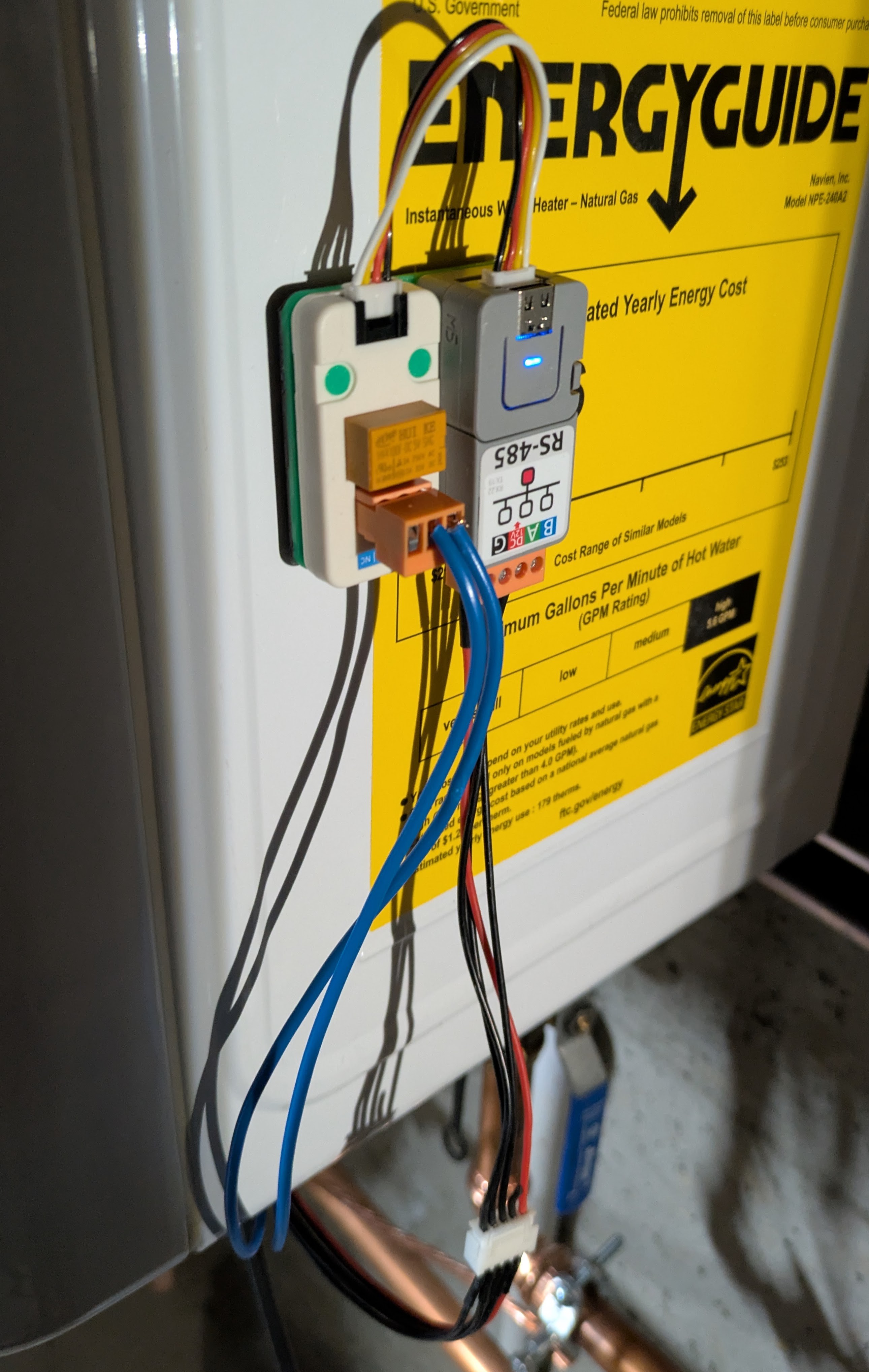
For the relay contact wires, I just reached into my junk drawer an pulled out some wires that I thought would be easy to clamp into the screw-down terminal of the relay. They're pretty thick (blue in the photo) even though they need to carry next to no current. That also made them easy to bind to the screw terminals on the control board.
In my original implementation, I also had a simple momentary push-button wired to the control board in addition to the relay device. That was so I could troubleshoot things without going through any of the fancy-schmancy automation logic. After that first day, I never used that button again, so I removed it this time around.
Except for possibly pondering some of the additional information reported over the RS485 interface, this project is done. I don't intend to implement any additional controls from my electronics to the water heater.
Discussions
Become a Hackaday.io Member
Create an account to leave a comment. Already have an account? Log In.