William Oprey
-
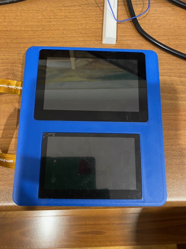
Finished - ish
08/22/2025 at 10:58 • 0 comments![]()
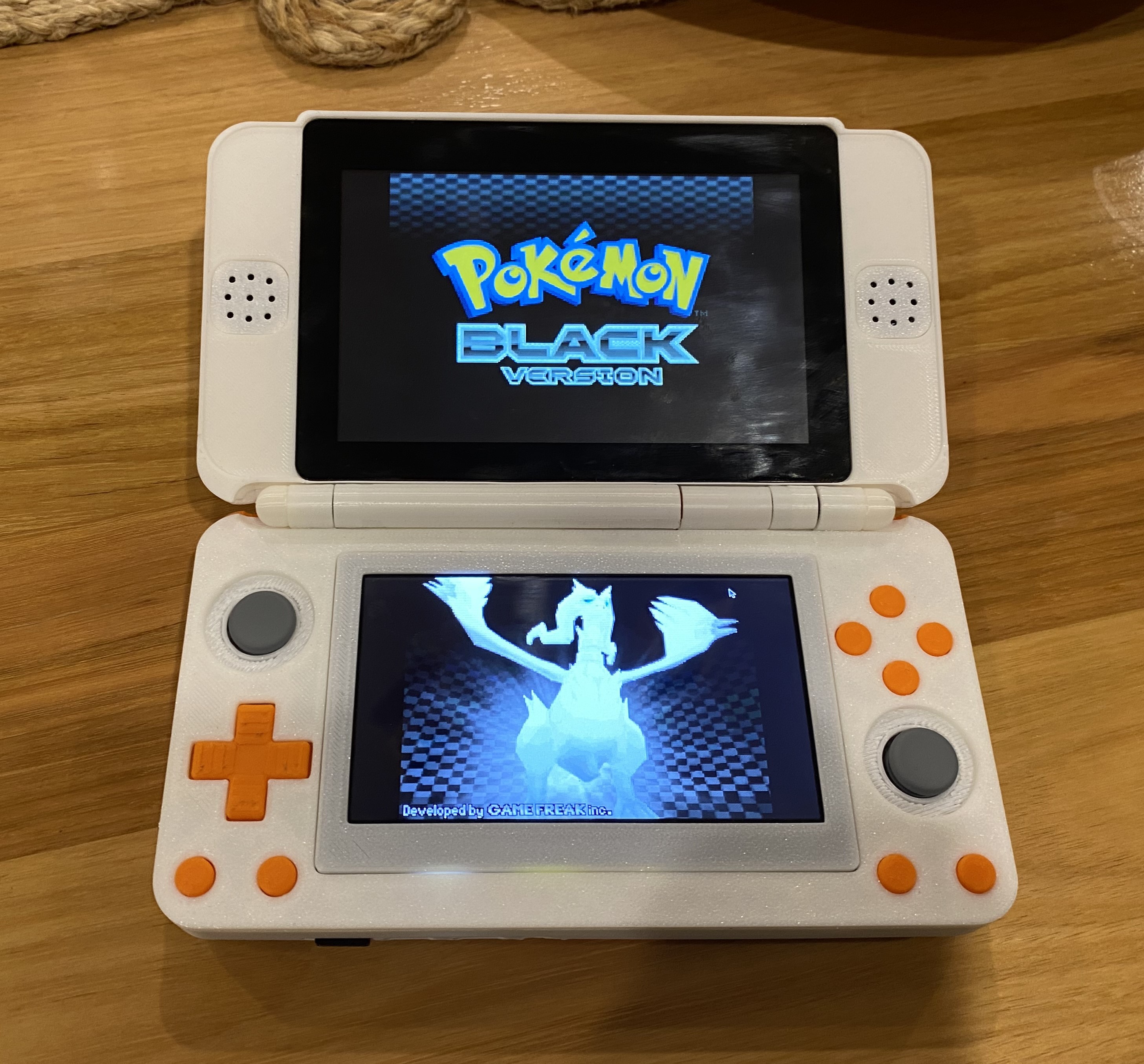
Yeah as the title suggests i've done a lot recently. The thing now has 2 screens, a hinge, and works pretty good. Github is here: https://github.com/borpendy/DSpi. I'll probably do a longer write up on the pcb design at some point soon.
-
Its been a while
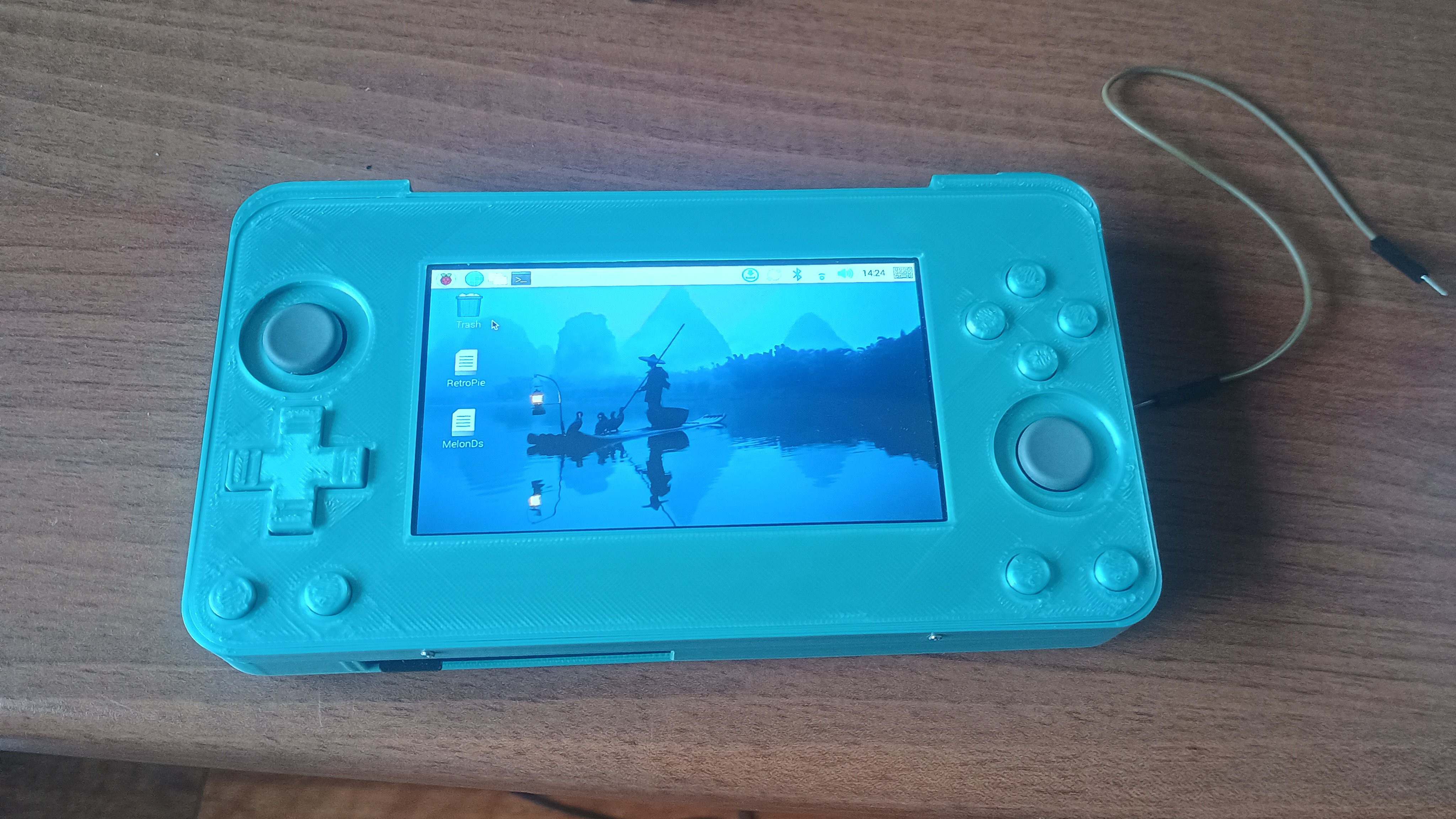
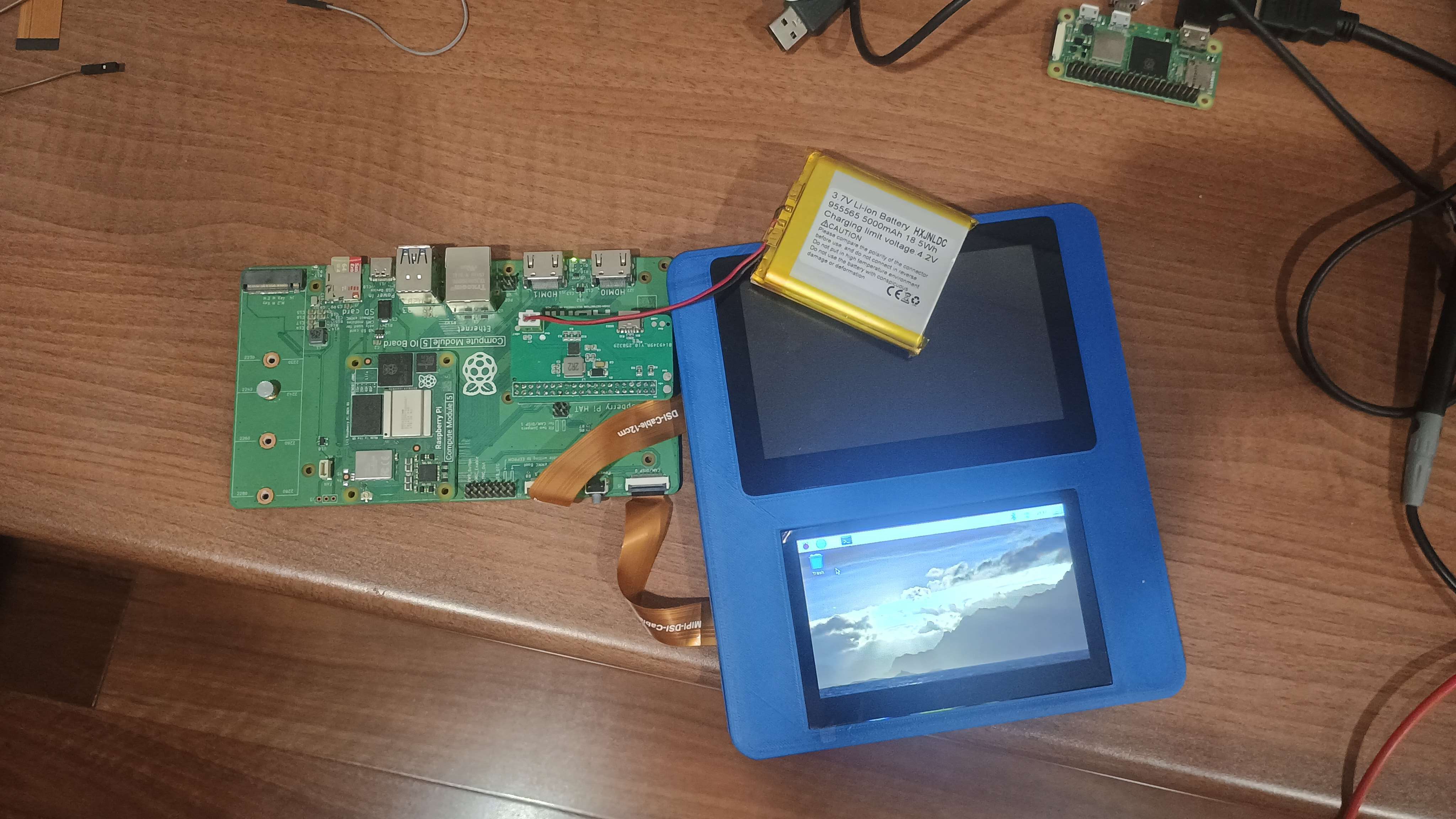
07/07/2025 at 04:41 • 0 commentsHey guys, sorry for disappearing for a bit, uni has been literally trying to kill me with workload. Its finally winter break now, so we're back. Motherboards have arrived, and mostly function, meaning I now have a semi functional handheld sitting in front of me.
![]()
Hey look, it's half a ds Issues include, but are not limited to: Broken 2nd screen connector, Incorrect MCU making BMIC configuration difficult, Broken headphone jack, The thing being fat as f***, so yeah lots to work on.
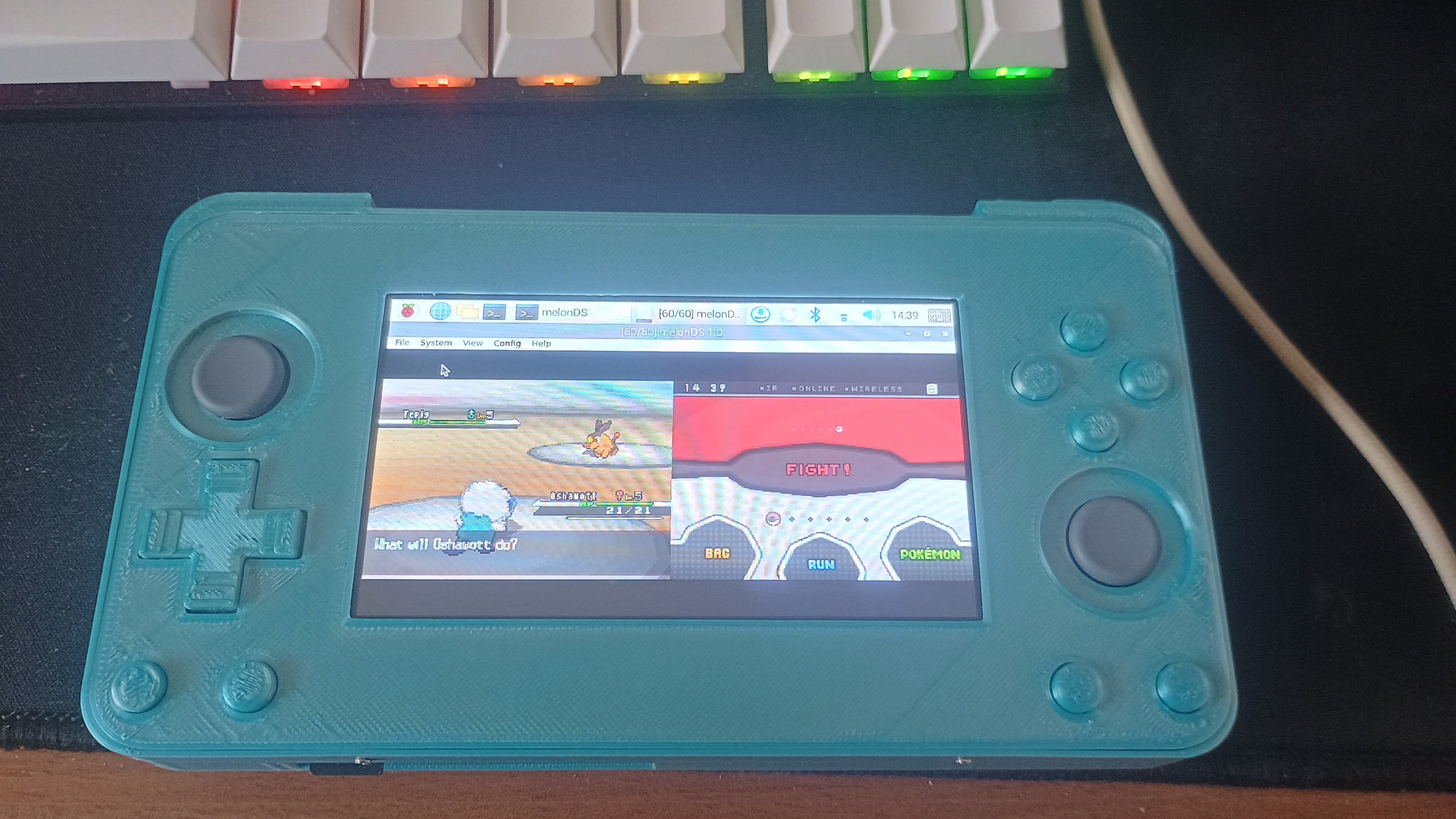
Apart from that everything seems to work fine, and I got retro pie running pretty easily. Ironically, in its current form ds games suck, since each screen gets a whopping 2 inches of size, but that's an issue for another revision.
Also Linux sucks and I resent it's very existence
![]()
Yeah this isn't great I've finally decided that I will open source this project, so expect a GitHub up in the next week or so
-
Quick update
05/04/2025 at 12:35 • 0 commentsSmall update log this week, the mainboard for the project has been designed and ordered. ETA is 1 week from now. I will probably go over the design and testing stuff next week as this has been pretty difficult, and I want a break.
![]()
![]()
-
Power is finished (ish)
04/21/2025 at 12:07 • 0 commentsLatest update, the power module is almost fully complete. To help anyone else attempting a similar project, I figured I'd outline what I've done, and how everything works, now that I know it works.
The requirements for the DSpi power stage are fairly non demanding. I am going off the Raspberry pi 5 power specifications, as it uses most of the same hardware as the compute module 5, and is freely available. The RP5 requires 5 amps at 5 volts for full operation, which is a stupid specification for numerous reasons, most notably that almost all USB power supplies, even fancy USB PD ones, only provide up to 3A of current. Luckily, you can run a RP5 off 3 amps, with a restricted USB power output (down to 600mah).
Since we need the thing to be portable, we need a battery, and PMIC solution, as I have discussed in the previous entry. In this case I am using a single 5000mah Lipo, with a BQ25890 BMIC chip from TI, and a TPS61022 boost converter to supply the system, since we need to push the lower battery voltage back up to 5v. A STM32 MCU is also included on board, as the BMIC has some I2C registers that must be set on start-up, such as peak charge current, input current limit ect. Components are connected as per the diagram below:
![]()
System diagram Of course, each IC needs its own auxiliary components, especially for the buck converter and BMIC modules, meaning the full design is quite a bit more complicated. Luckily the reference layouts provided by TI work decently well, and are easy enough to understand.
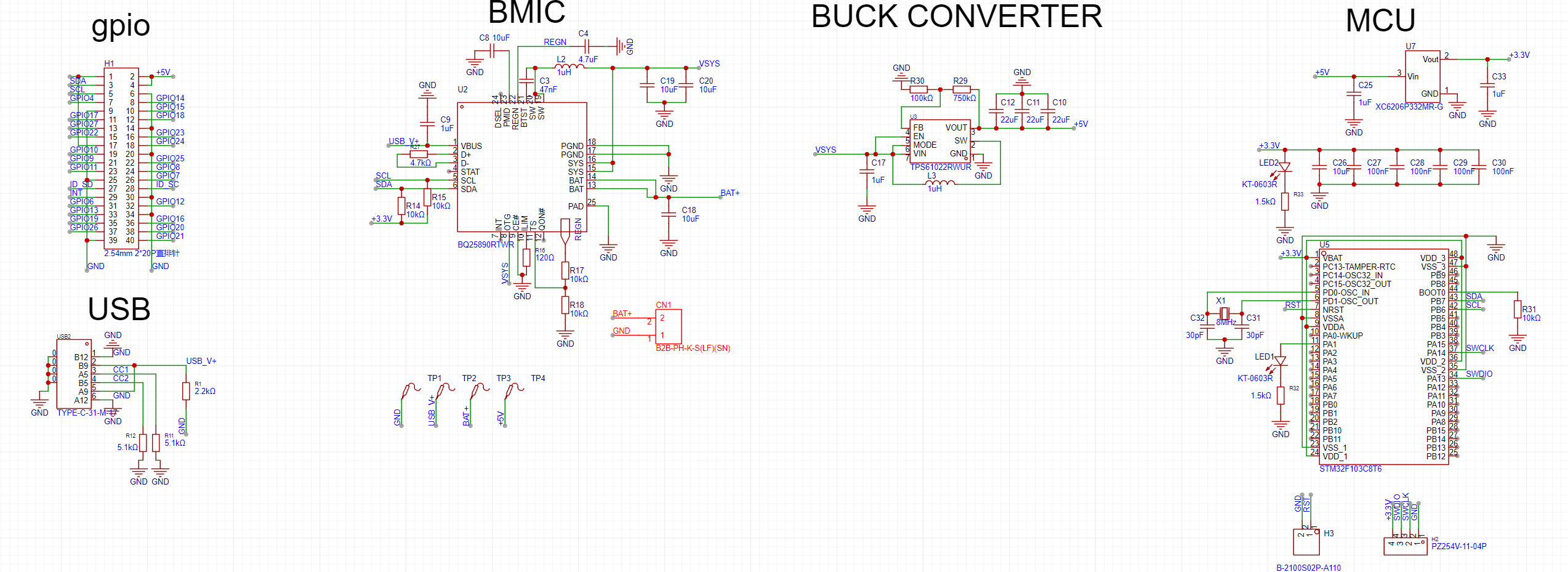
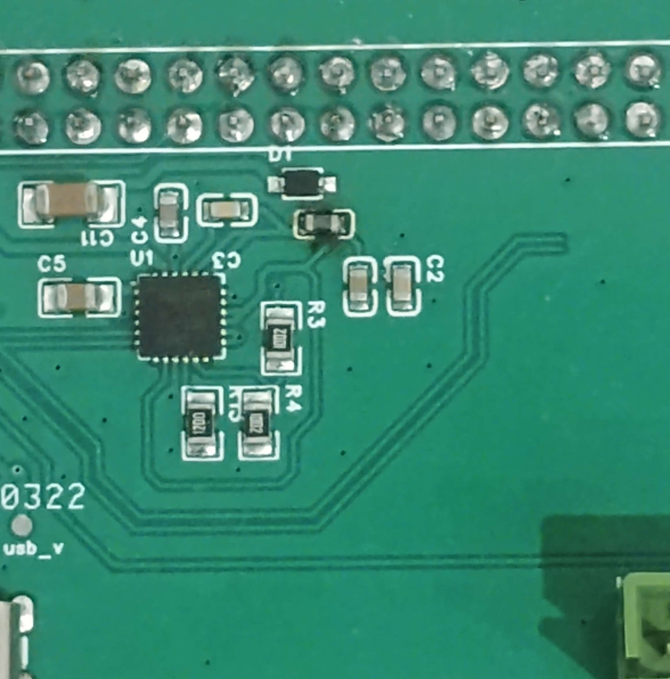
After a bit more design work, I now have a fully functioning board, and the pi now works both off, and on charge. I'll probably publish proper design files on github later, but for now, here is the design schematic, as reference for anyone interested.
![]()
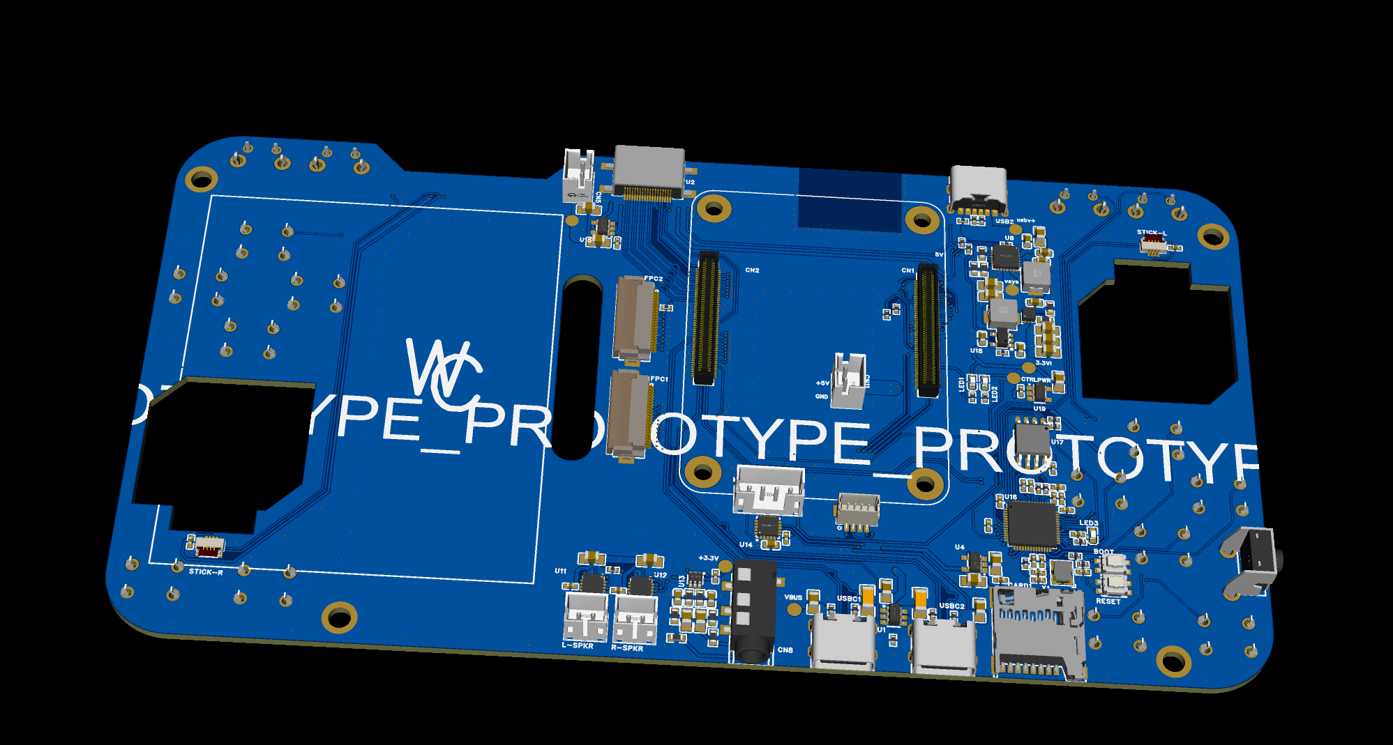
Charge module schematic Now that the power work is complete, we can get into the fun stuff, and get this device looking more like an actual console. Some super secret stuff I've been working on is below.
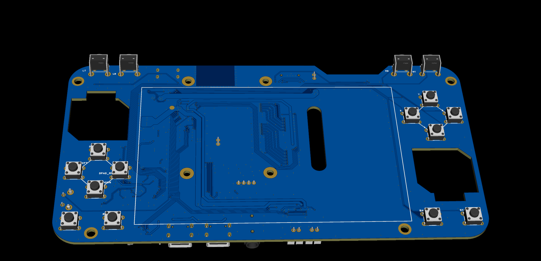
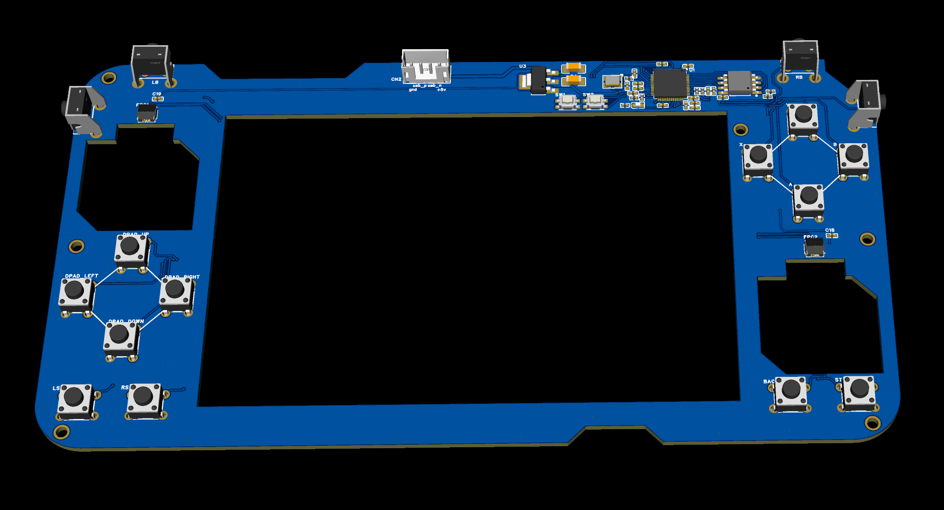
![]()
WIP Controller board ![]()
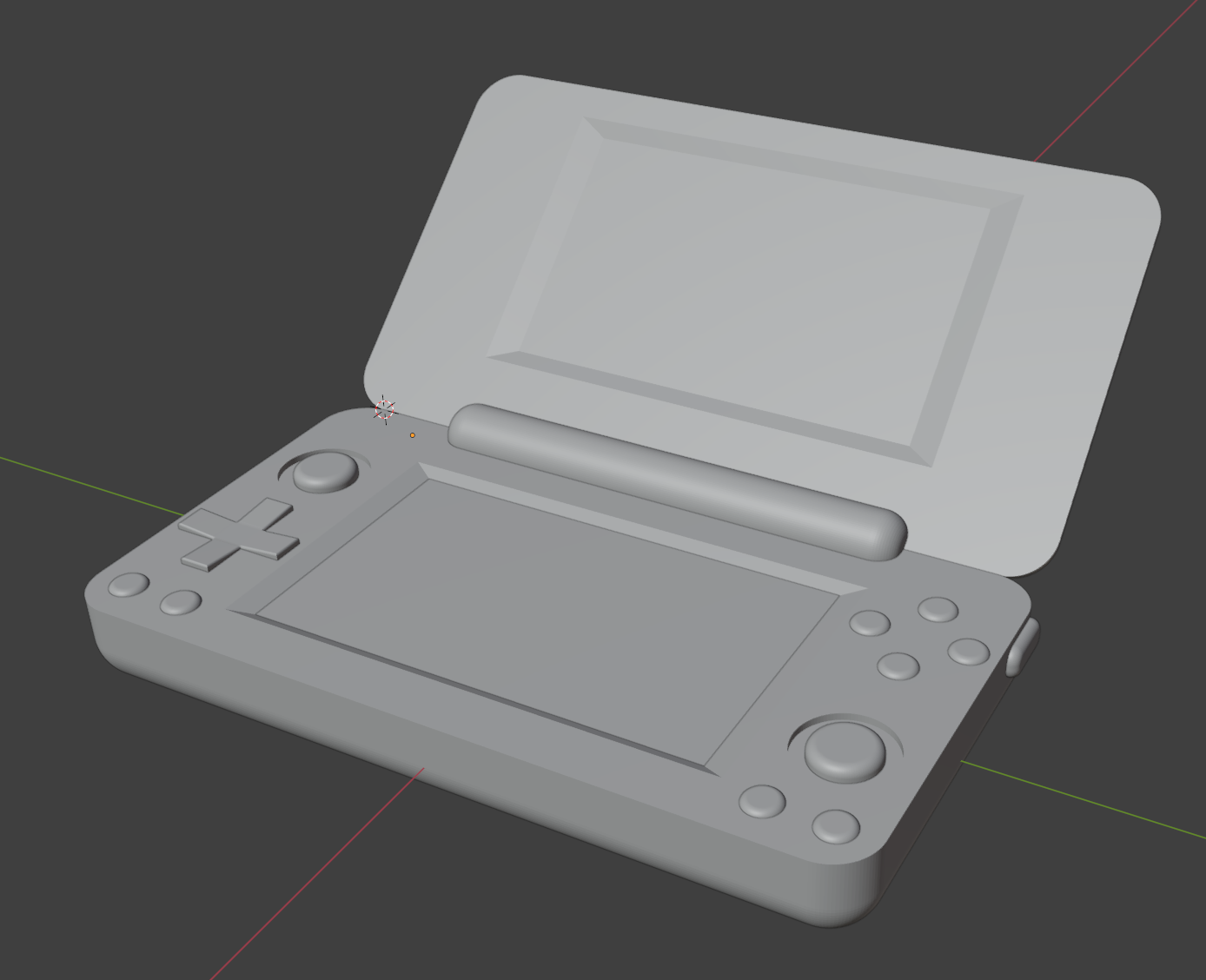
Preliminary modelling -
(No) Power to the people
04/06/2025 at 10:44 • 0 commentsFirst thing on the agenda: Batteries. Obviously, a handheld console that only works when plugged in would be pointless, so we need a portable power source. Luckily, we can do what everyone else does, and use a LiPo.
LiPo batteries have a few caveats in use. For one, they come in discrete cells, with each cell having a voltage varying from 3-4 V. If a cell is discharged to under 3V, it becomes internally damaged and cannot be used anymore, and if a cell is charged significantly past 4V, they tend to explode, which is not good for you, or anyone in your immediate surrounds. If multiple cells are used, they also have to balanced while charging, or you guessed it, they explode.

LiPo malfunctions are fun... Luckily, basically every consumer device ever is powered by one of these things, and since last time I checked we are all still alive, we've gotten pretty damn good at using them. Practically, this means there are plenty of off the shelf BMIC (Battery Management Integrated Circuit) modules that provide all functions required to safely charge and use a LiPo battery, with some drawbacks. Because this project will be extremely space constrained, in its final form, I have no choice but to integrate the charge and power supply modules into the final "mainboard" PCB, meaning no cheating using a PiJuice module, or similar hats. Because I'm not made of money, I have, and will be prototyping these module on a separate PCB, before integration into the final product.
The saying "Move fast and break things" has been stolen and heavily misused by business types lately, however in prototyping, the saying remains very literal. Since I'm using TI charge modules, I can just rip off their example circuit layouts with little consequence, however component selection is a different matter, and when you forget that Amperage ratings exist for a reason, bad things happen:
![]()
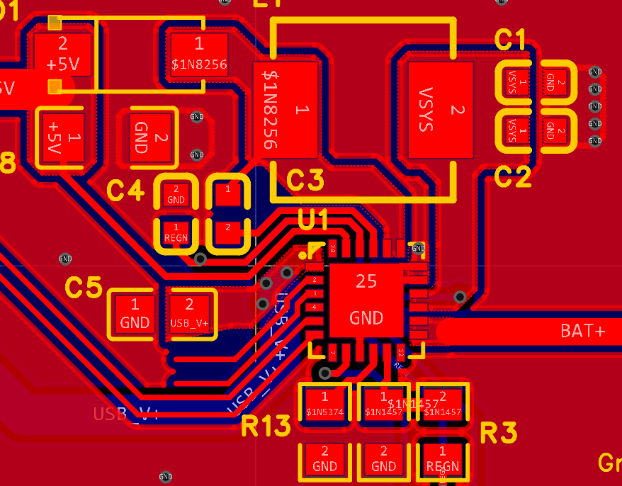
Oops... One burnt inductor later, back to the drawing board. What I neglected to realise is that the BMIC I'm using, the BQ25895, features an integrated buck boost voltage converter. This operates at the full supply amperage of the load, meaning a real beefy inductor is required to avoid "rapid thermal failure". Buck converter design also has a few other caveats, that I had neglected, as they require quite large traces, to avoid impedance issues, while also requiring a minimal loop area between the inductor and BMIC, for EMI reasons. One redesign later, and I had a (mostly) working board:
![]()
A more competent buck design, note the small current loop and full ground plane
Testing the resulting boards, the best I can say is that they almost work. While battery charging works perfectly, the BMIC I'm using has given me some "unique" issues. As the IC has to not only buck any input power down from 5v to 4v while charging, but also boost the battery output from 4v to 5v while supplying, the onboard switching regulator must switch between buck and boost function, depending on the voltage input. This cannot be done instantly, requiring a 40ms delay, which unfortunately is enough time for the Pi to run out of power and die. In practical terms, this means every time the Pi is taken off charge, it shuts down, something that gets very annoying very fast.
The other issue I'm facing is much less technical, and much more idiotic. Turns out that when plugged in, the BMIC bypasses the regulator and supplies the full system output through another separate pin, in this case a pin I basically ignored, and made 0.2mm thick. Obviously, pushing 3A though 0.2mm of width causes problems fast, and in my case the resulting voltage drop is enough to immediately shut down the Pi, meaning the thing won't work on charge either.
So, much work to be done, but on the upside, the Pi is portable now (With massive, impossible to ignore issues)
![]()
No wires :) Next steps include sticky taping an external buck converter to the board, to hopefully fix those dropout issues, and actually reading datasheets next time like a real engineer.
-
Proof of Concept
03/29/2025 at 10:02 • 0 commentsOk, enough ****ing around, time to do some concrete work. To prove that what I want can even be done, I have obtained some test hardware, in the form of the reference CM5 IO board. This one is designed by professionals, so there won't be a million possible reasons for failure if anything goes wrong (foreshadowing).
The CM5 comes stock with two DSI (Display Serial Interface) channels onboard. This is nice, because it makes the entire project possible at all, basically, by completely sidestepping the need for HDMI connections (Fat and annoying) when running screens, of which I will be needing two. Luckily I also had some DSI screens kicking around, and after about 5 minutes of CAD, and 2 hours of printing (ugh), I had the following "Not 2DS" in my possession:
![]()
(Sidenote: DSI is basically identical to DSi, as in the DS variant. This fact is sorta funny right until you google DSI screen, and the resulting search is full of DS content, rather than anything remotely related to what you actually want)
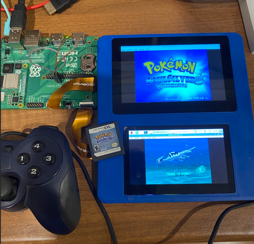
Enabling the screens required some messing around in the Rasbian config folder, but once done everything seems to work perfectly, including touchscreen input on both displays. From here, emulator install was the next step. MelonDS currently seems to be the emulator to beat, and supports multi window/screen output while emulating (part of the reason this project was even started), so it was the obvious choice. Because Linux, the emulator has to be built from source, but luckily the Devs of MelonDS have a great write up on how to do this, over at https://github.com/melonDS-emu/melonDS/blob/master/BUILD.md, and I can confirm the ubuntu instructions work perfectly for Raspbian.
Next up, get my "legal" copy of Pokémon Soul Silver, and enjoy:
![]()
-
First steps
03/29/2025 at 09:14 • 0 commentsSo...... Guess I'm doing this now. Ok, to explain why on earth someone would want to dedicate hours of their life to making a worse DS, you really need to experience DS emulation on mobile. Long story short, it sucks, for a great many reasons mostly related to Nintendo's insistence on using the most gimmicky features ever to make up for their perpetual lag on hardware. Admittedly in this situation the sane response would be "Buy a 3ds xl" and not "Design a full new system to pretend to be a DS", but this is cooler.
Also, designing something that, to my knowledge, hasn't been done before sounds fun, and hopefully looks good on the resume, so why not. Anyway as this is my first real hardware level project, I will be doing a lot of stealing. Mostly from Texas Instruments, and their pretty great datasheets for basically everything, but also from the one other compute module handheld on the internet, found here: https://github.com/StonedEdge/Retro-Lite-CM5. This guy is much better than me, and I hope to get even remotely close to the quality of their work.
Anyway this will probably take the next 1000 hrs of my life, so might as well get started now. See ya
DSpi: Rasberry Pi 5 Clamshell Handheld
Handheld gaming system in the DS form factor using the RasPi Compute Module 5