Arnov Sharma
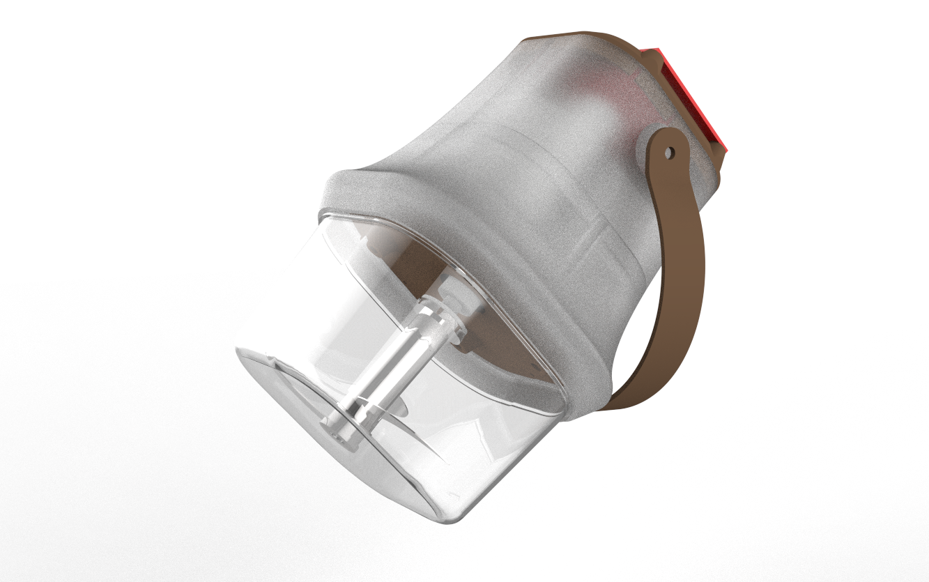
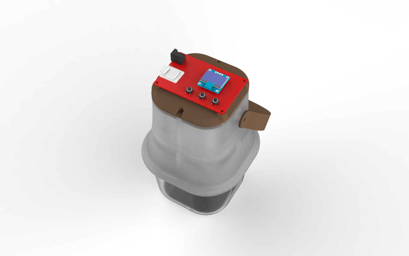
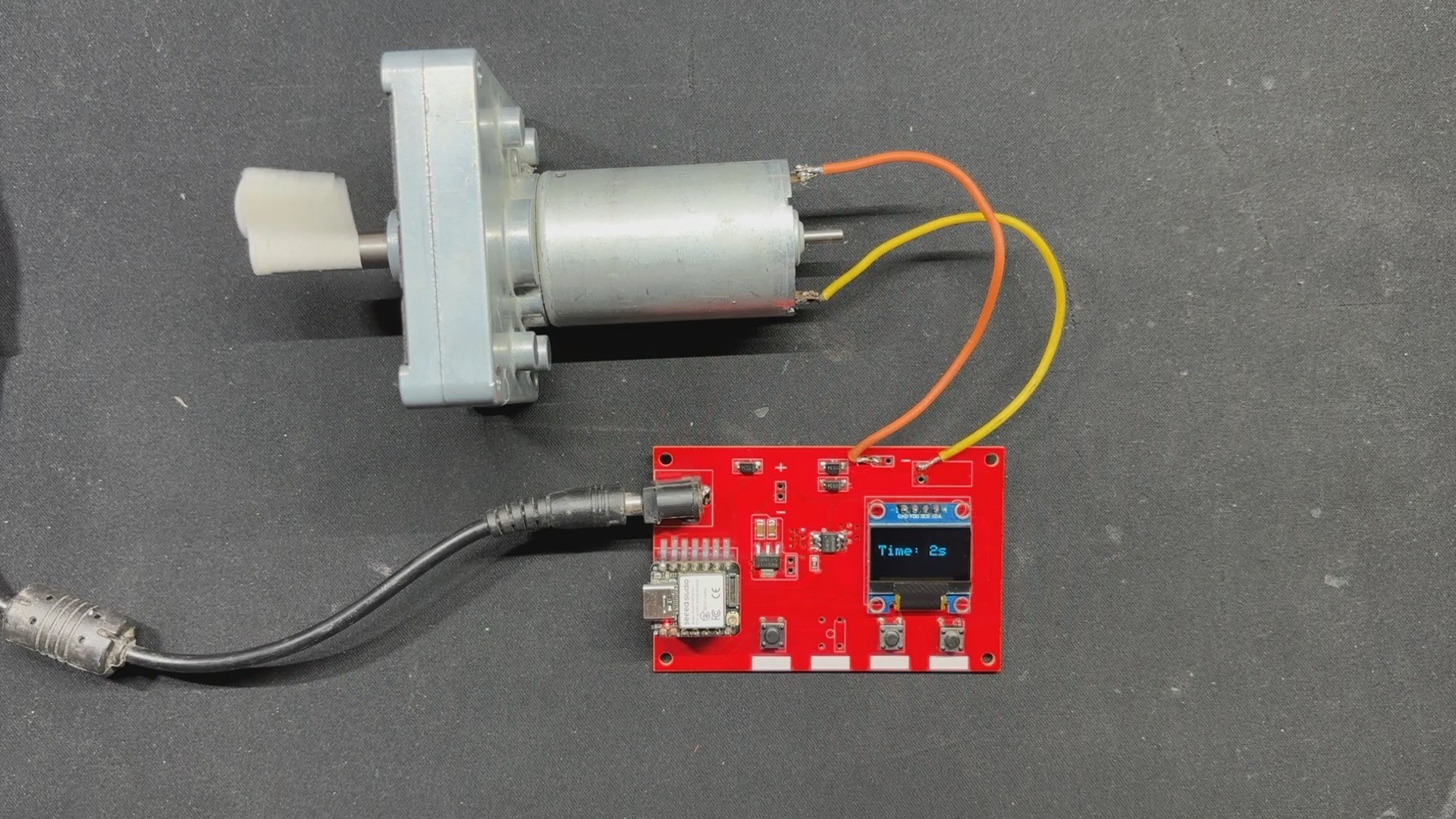
We took the jar and blade from a vegetable chopper, removed the mechanical element, and installed a motor to spin the blade. For controlling the motor, we designed a Custom XIAO ESP32 S3-powered Motor Driver Board with an OLED screen that displays the motor's run time.
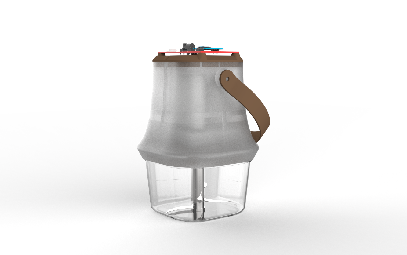
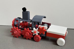
We designed the body in Fusion360 and even added a handle to allow it to be easily carried around or moved from one location to another.
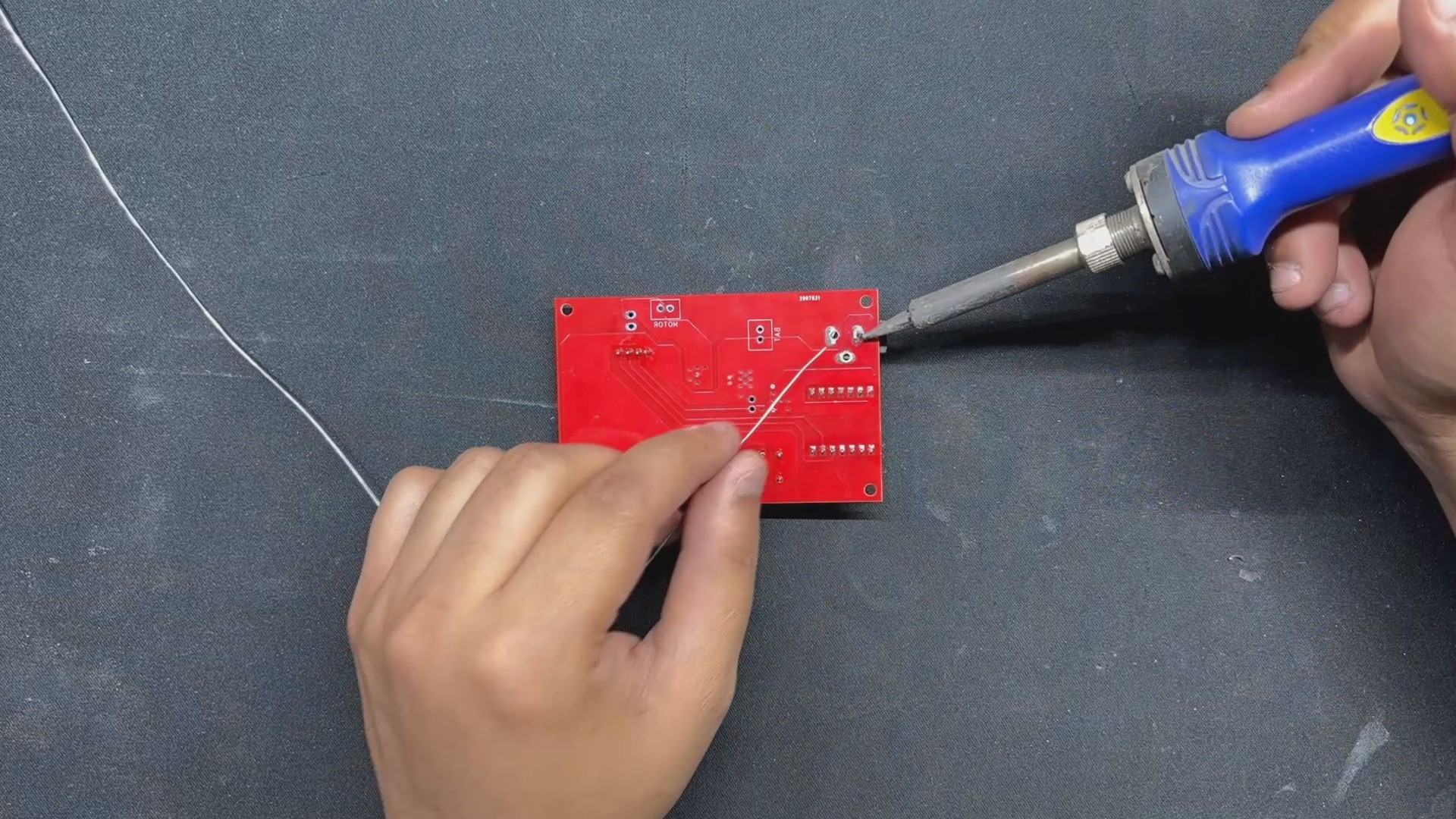
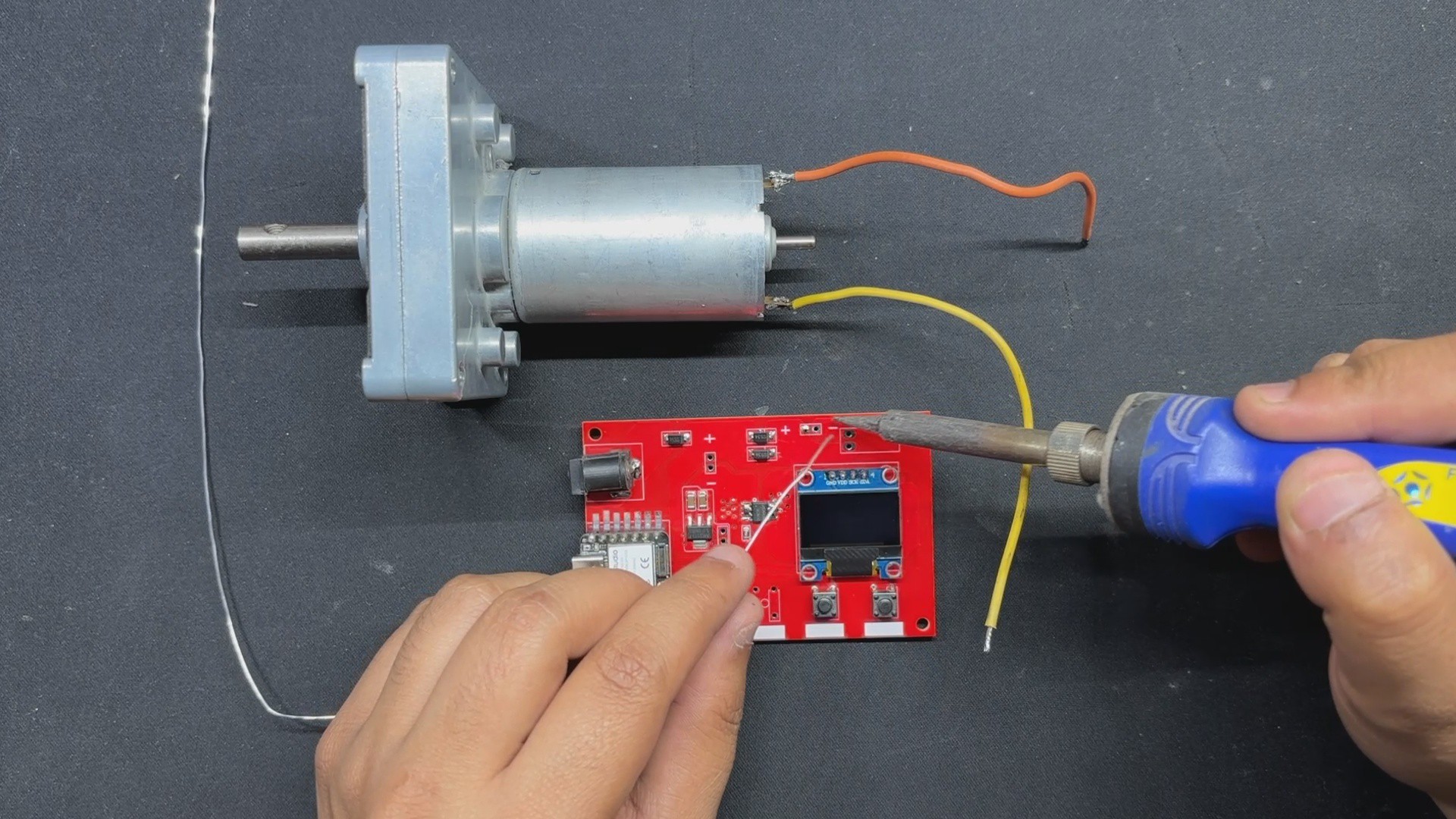
This device works by connecting a gear motor to the Blade part, which revolves inside the Jar. We power the motor with an onboard battery, and to regulate the motor speed and time, we utilize a microcontroller setup with buttons as input and a display to show the device's run time.
To test this project, we also created a small card out of paper pulp that we prepared inside our PulpPro.
3D DESIGN
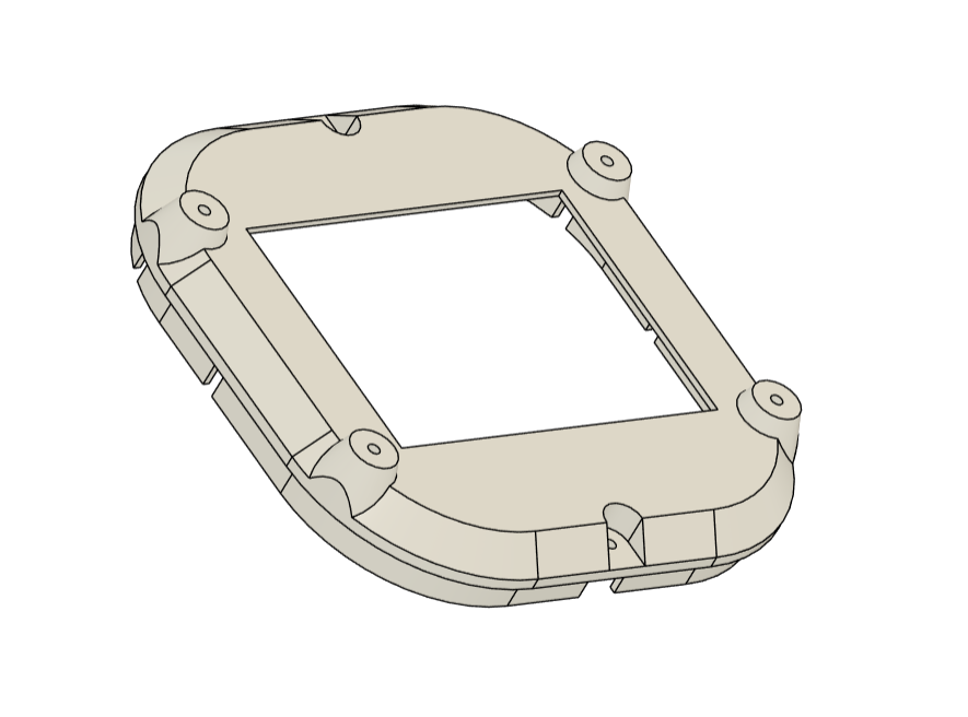
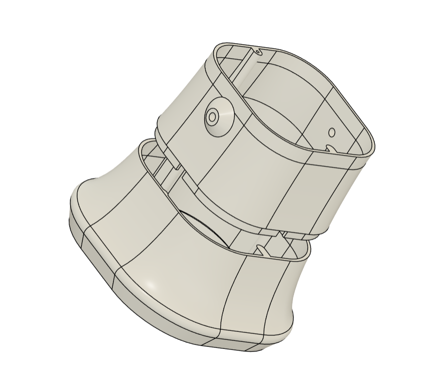
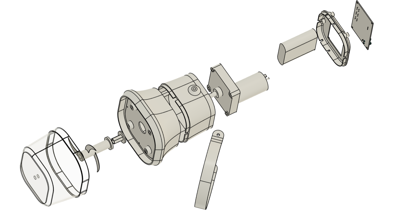
We started our project by designing our own blender, using an existing vegetable chopper's jar and blade. Jar and Blade were difficult to 3D print because the blade needed to be created by retrofitting a paper cutter blade, and the jar could be 3D printed but there would be a water leak issue, so we used the jar and blade from the vegetable chopper. We designed the remaining elements, which comprised the base body, which houses the motor and battery pack within, and the lid, which is put over the base body and holds the circuit in place. To keep the motor in place, we designed a motor holder that attaches to the bottom side of the base body.
The whole model was made in Fusion360, and we incorporated industrial design into this project by conducting research on the design of various types of blenders, and then we came up with our own sleek design that mounts on top of the jar and appears to be an extension of the jar rather than something retrofitted.
Also, we divided the Base body into two sections so that we could print them both fast. The entire time for printing the Base body was more than 24 hours, but by splitting the model in two halves, we were able to cut the time to 10 hours for each print.
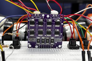
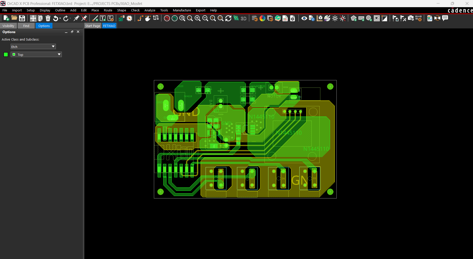
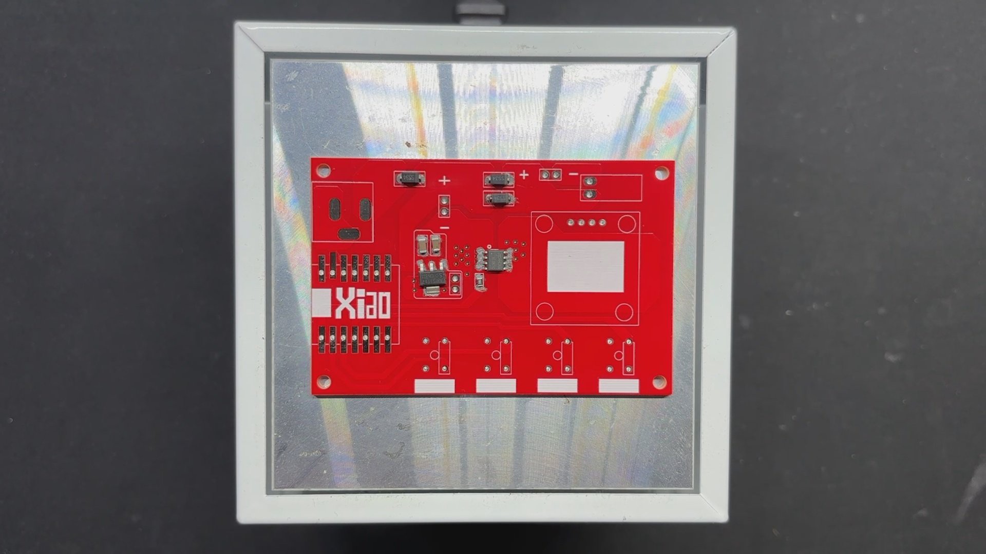
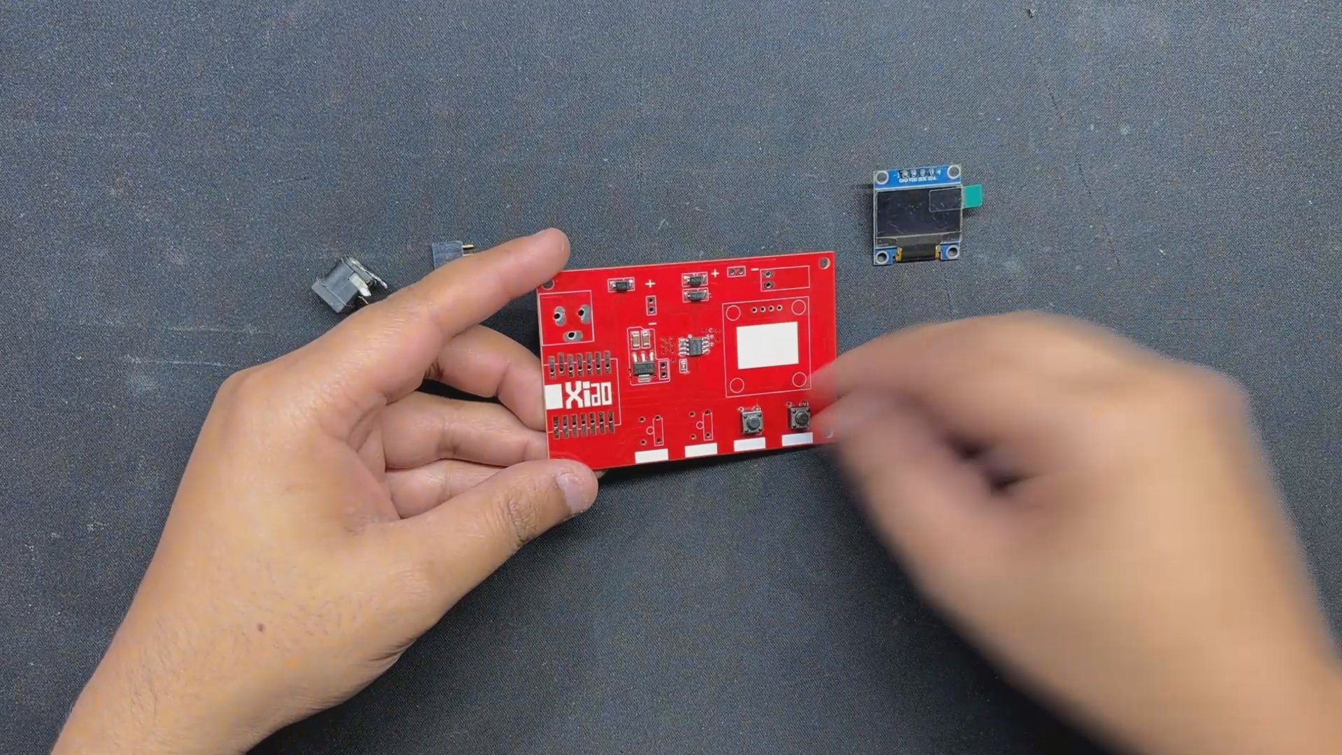
we created a custom circuit with four mounting holes that are attached to the lid using four screw bosses. On the circuit, we've added an XIAO Microcontroller model, followed by the SSD1306 OLED screen, four buttons, and a barrel DC jack. We will use the dimensions from this Cad file to create the board outline and position components during the PCB editing phase.
To give the 3D printed parts a visually appealing look, we 3D printed the base body in transparent PLA and the remaining components in brown PLA.
XIAO MOTOR DRIVER - CIRCUIT DESIGN
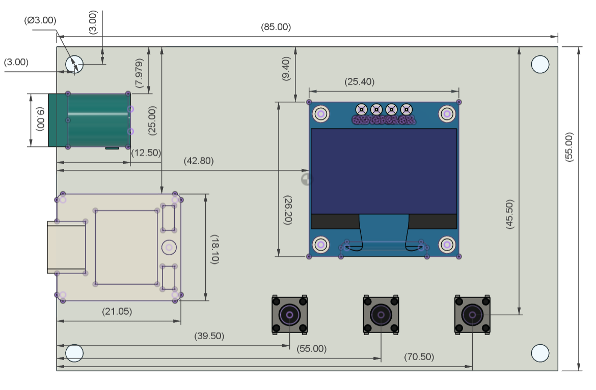
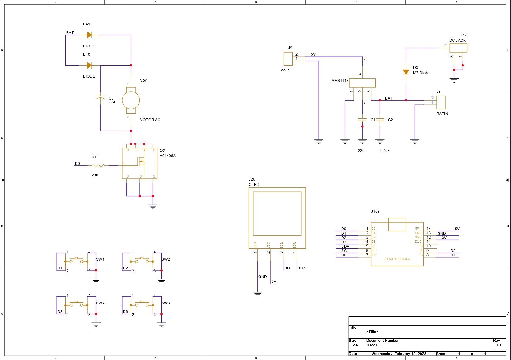
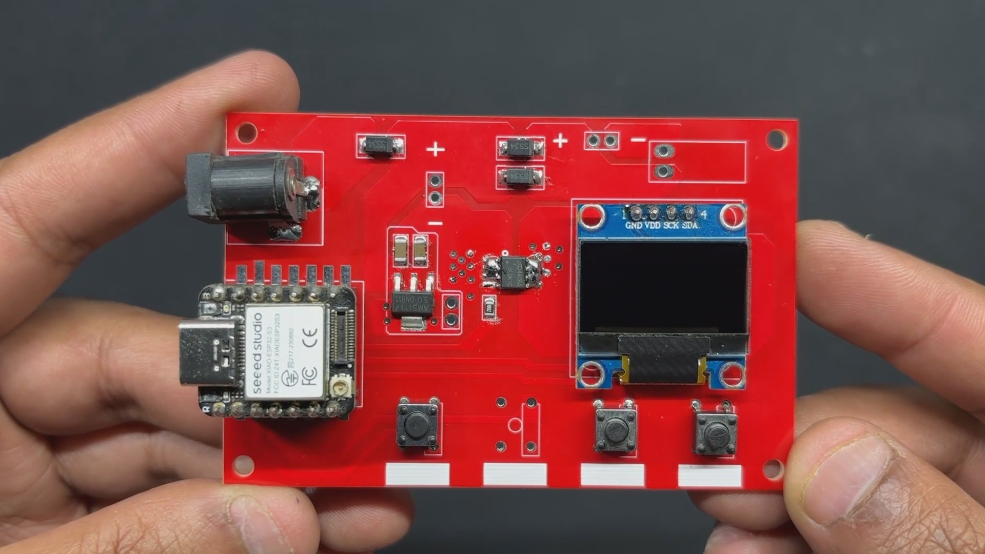
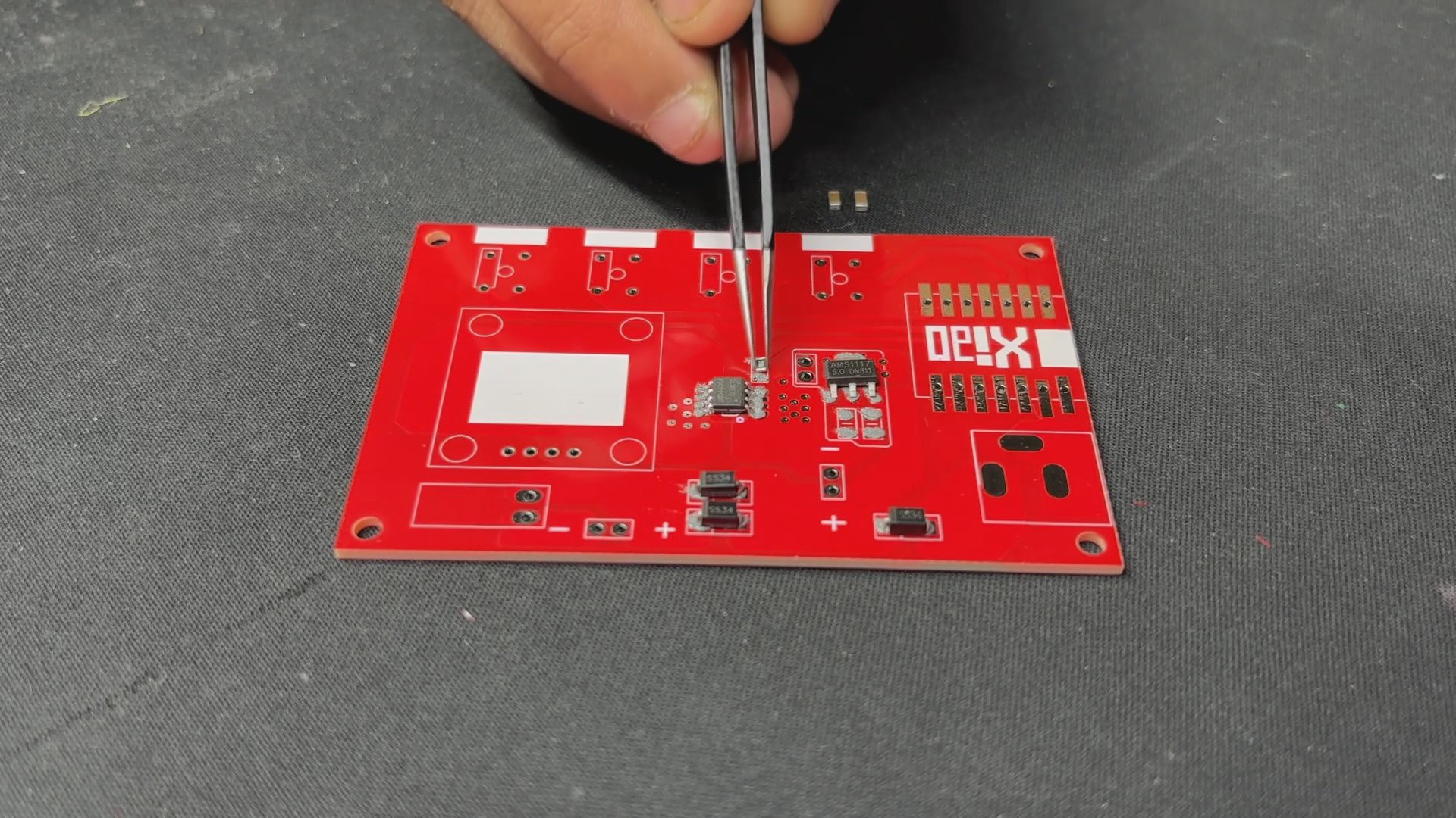
We began the Motor Driver Board design process by constructing a simple schematic that included an XIAO ESP32 S3 microcontroller linked to an AO4406A N Channel Mosfet IC. We are using the Mosfet as a switch setup, with our motor linked to the Mosfet and a 10K resistor connected to the gate of the mosfet via GPIO0 of the XIAO MCU. We can control this mosfet using GPIO0. In addition, we added four buttons with GPIOs 1, 2, 3, and 6.
OLED display is also used and is connected to XIAO's SDA and SCL pins, which are GPIO4 and GPIO5.
In this arrangement, we're utilizing a 12V battery and a 12V motor, but the XIAO is a 5V device, which means any voltage above 5V would fry the controller. To convert 12V to a stable 5V for XIAO and display operation, we used an AMS1117 voltage regulator configuration, which consists of an AM1117 coupled to two capacitors at the input and output.
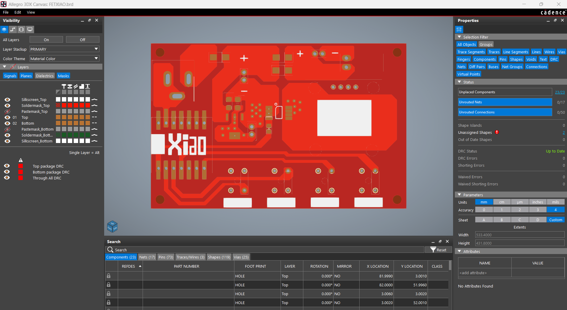
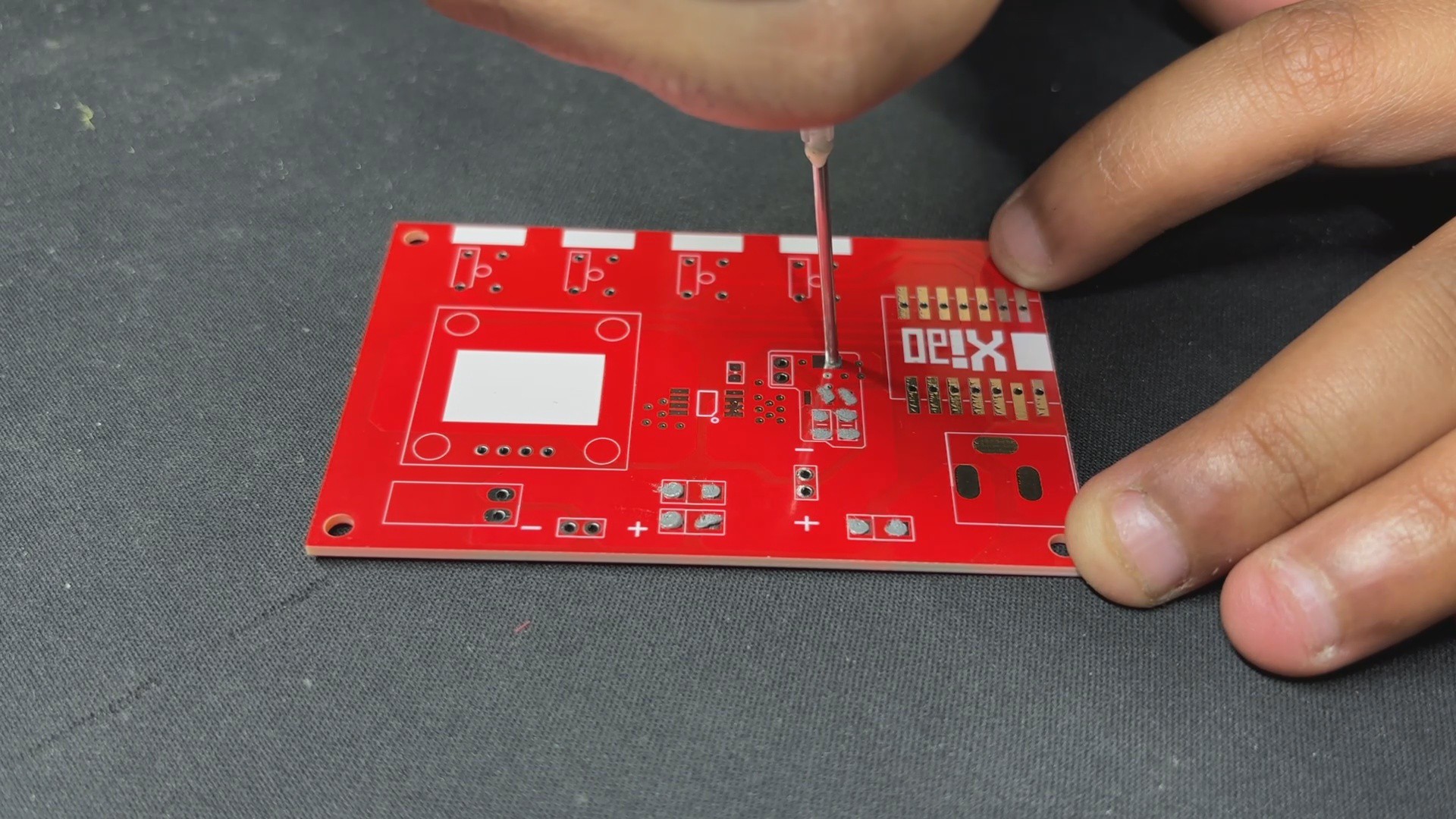
After finalizing the schematic, we prepare the board design for this project by following the board outline from the cad design and arranging all of the components according to the layout.
We complete the PCB design and prepare the Gerber data.
SEEED FUSION PCB SERVICE
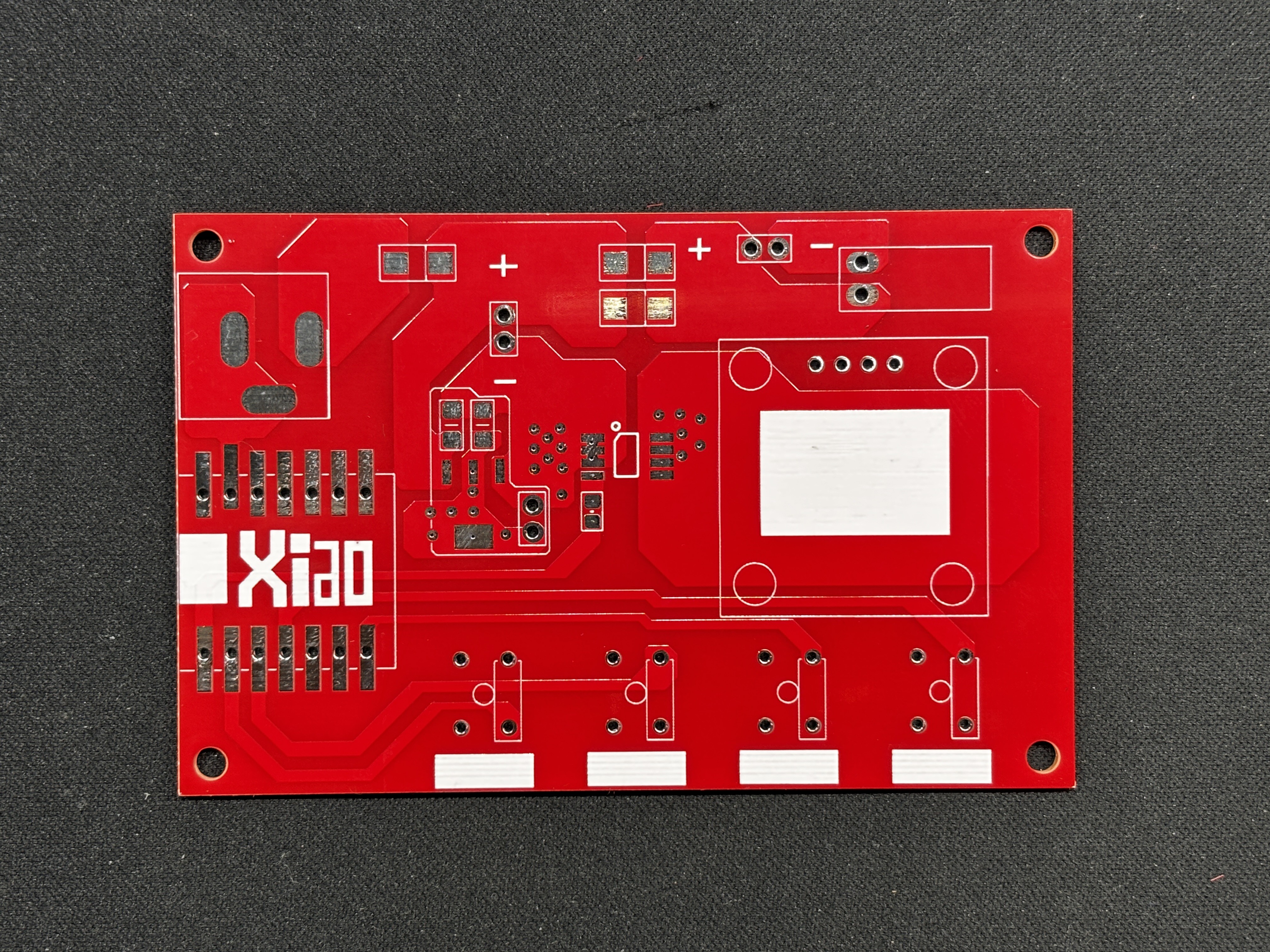

Following the completion of the Gerber data, we uploaded the file to Seeed Fusion's website and placed an order for a RED Solder mask with white silkscreen.
PCBs were received in a week, and their quality was super good...
Read more »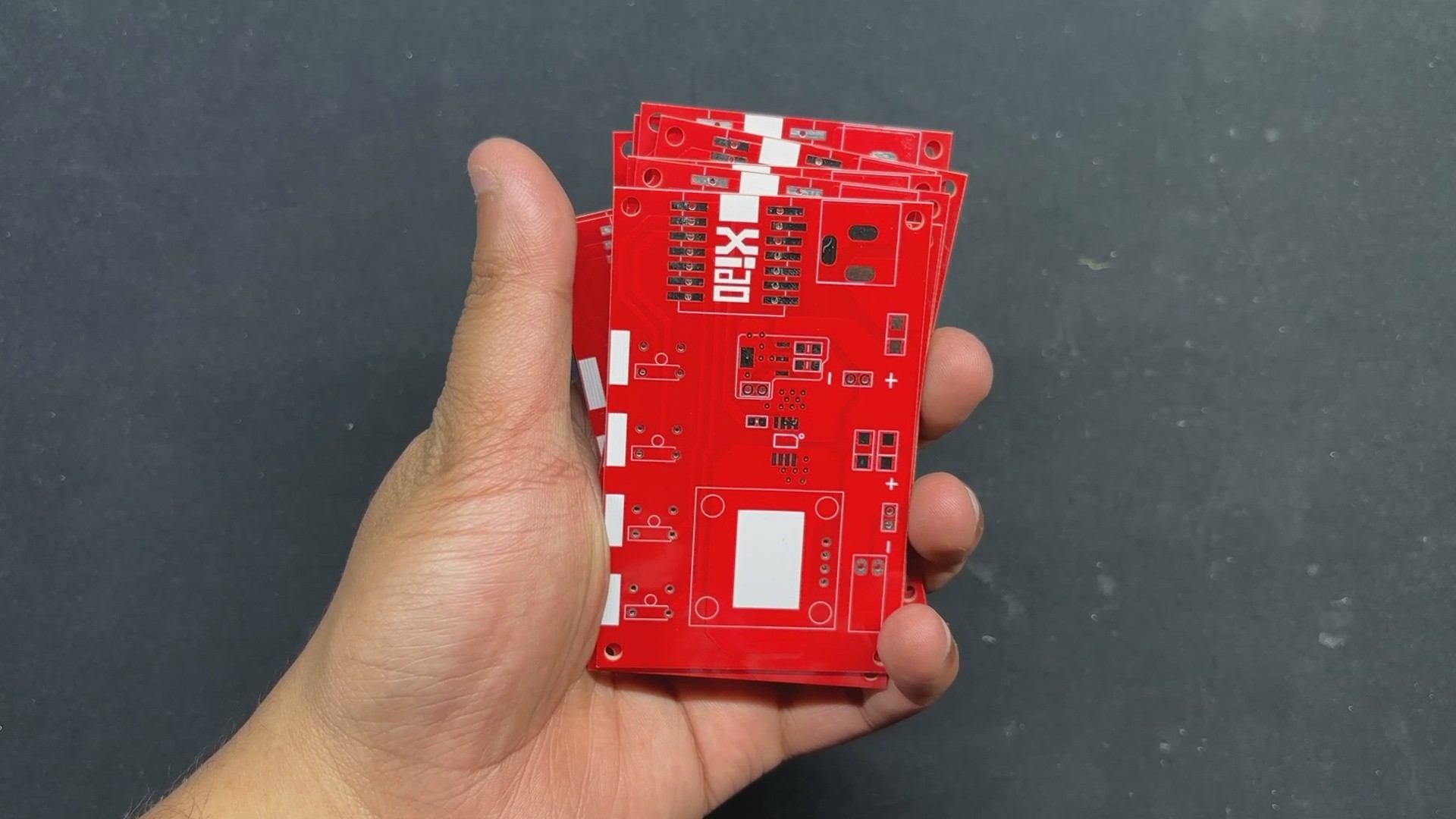
 Mrinnovative
 gokux
gokux