 Arnov Sharma
-
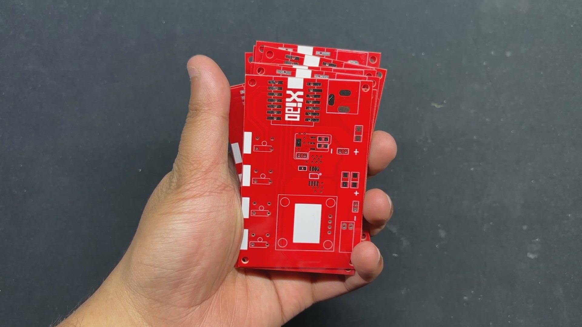
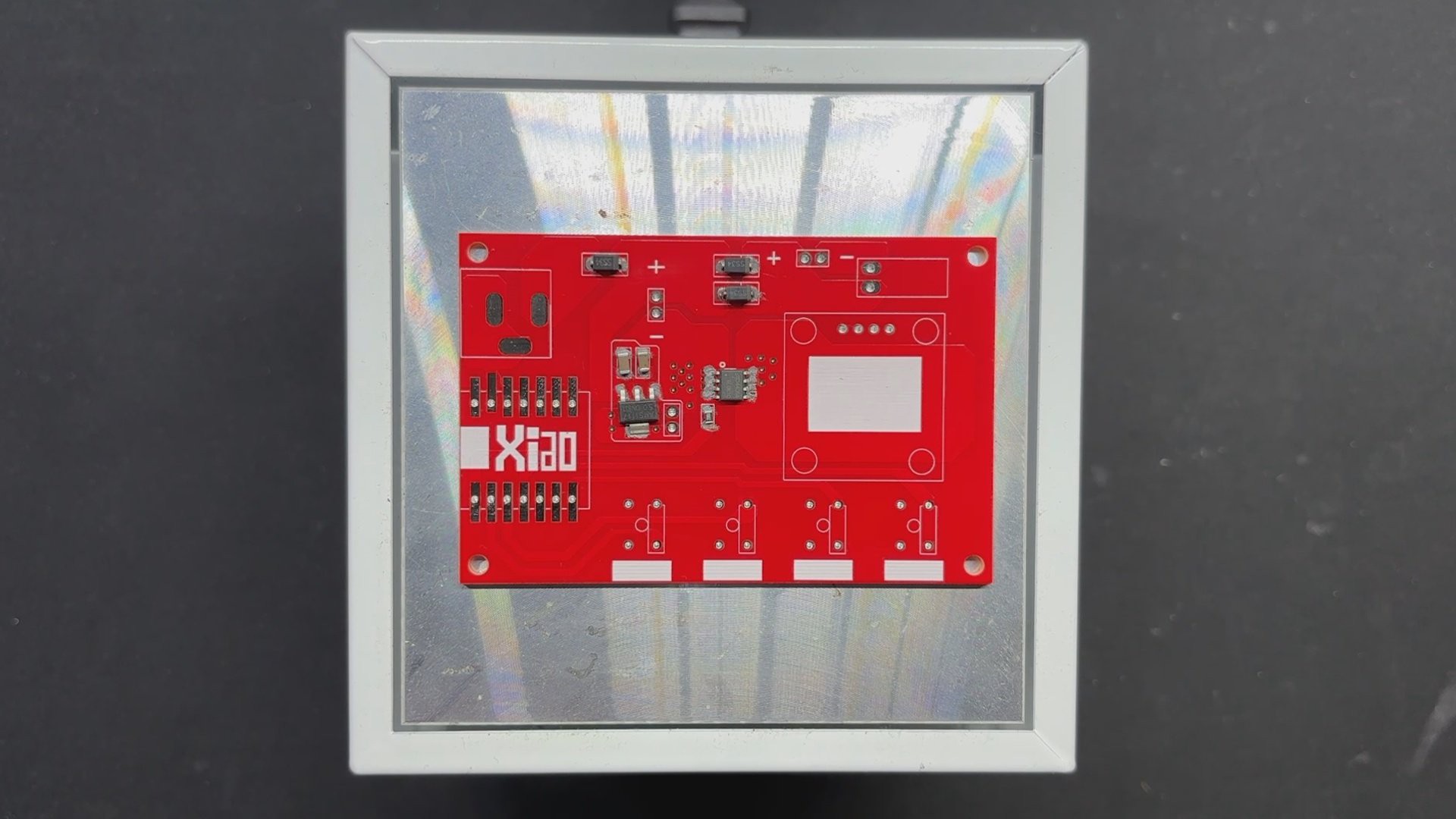
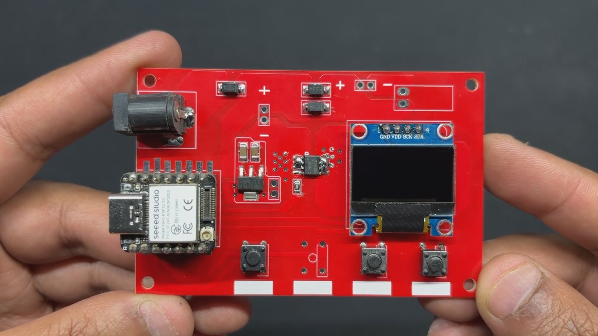
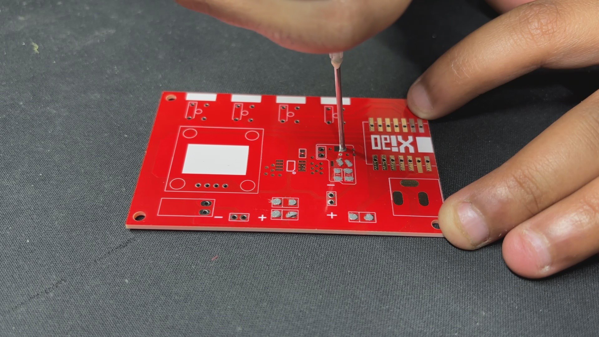
1PCB ASSEMBLY PROCESS
![]()
![]()
![]()
![]()
![]()
![]()
![]()
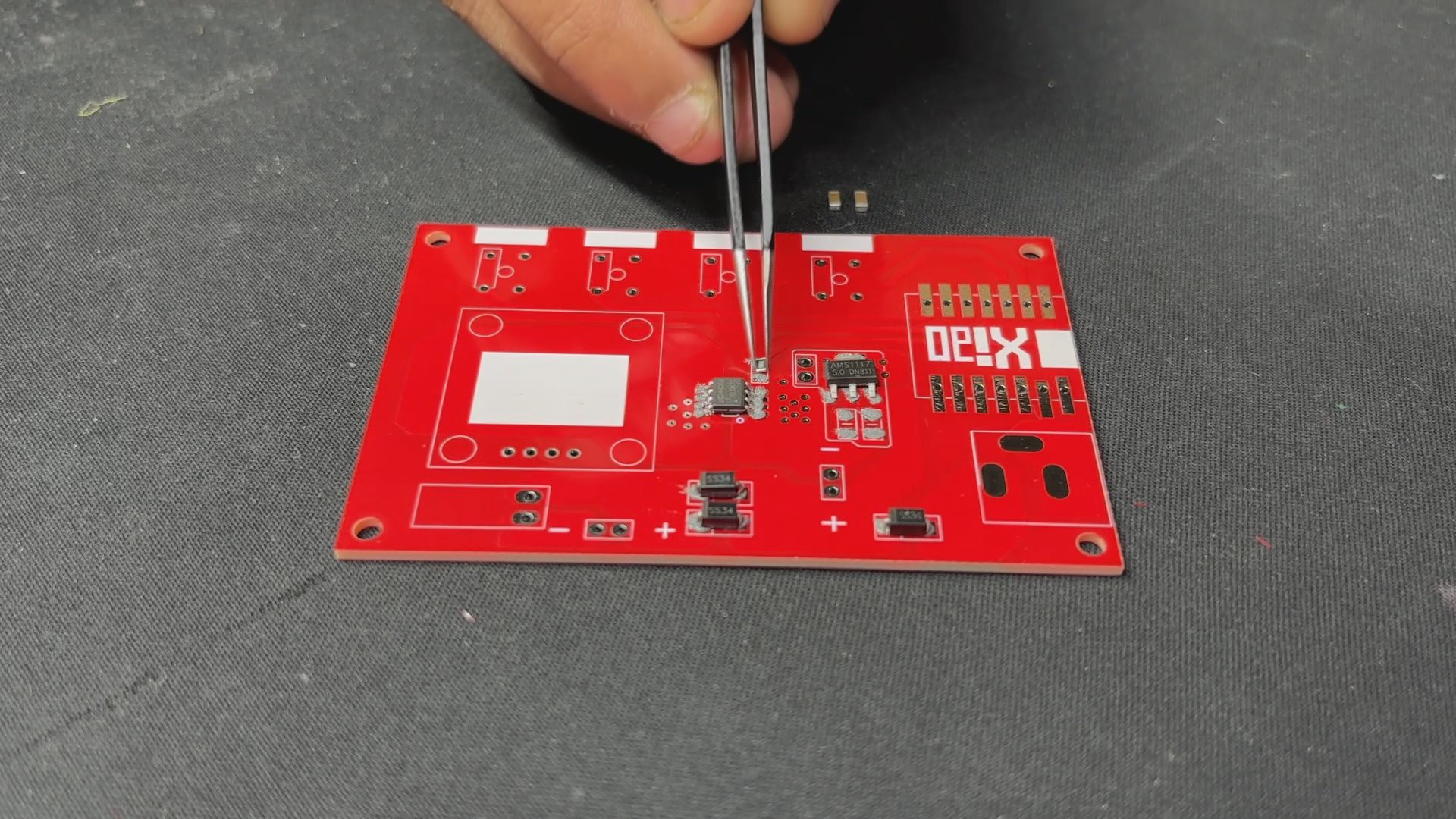
- The PCB assembly process begins by applying solder paste to each SMD component pad one at a time with a solder paste dispensing syringe.
- We then use an ESD Tweezer to pick and install each component in its proper location.
- The PCB is then placed on the reflow hotplate, which heats it from below up to the solder paste melting temperature in order to melt the solder paste and permanently solder all of the SMD component pads.
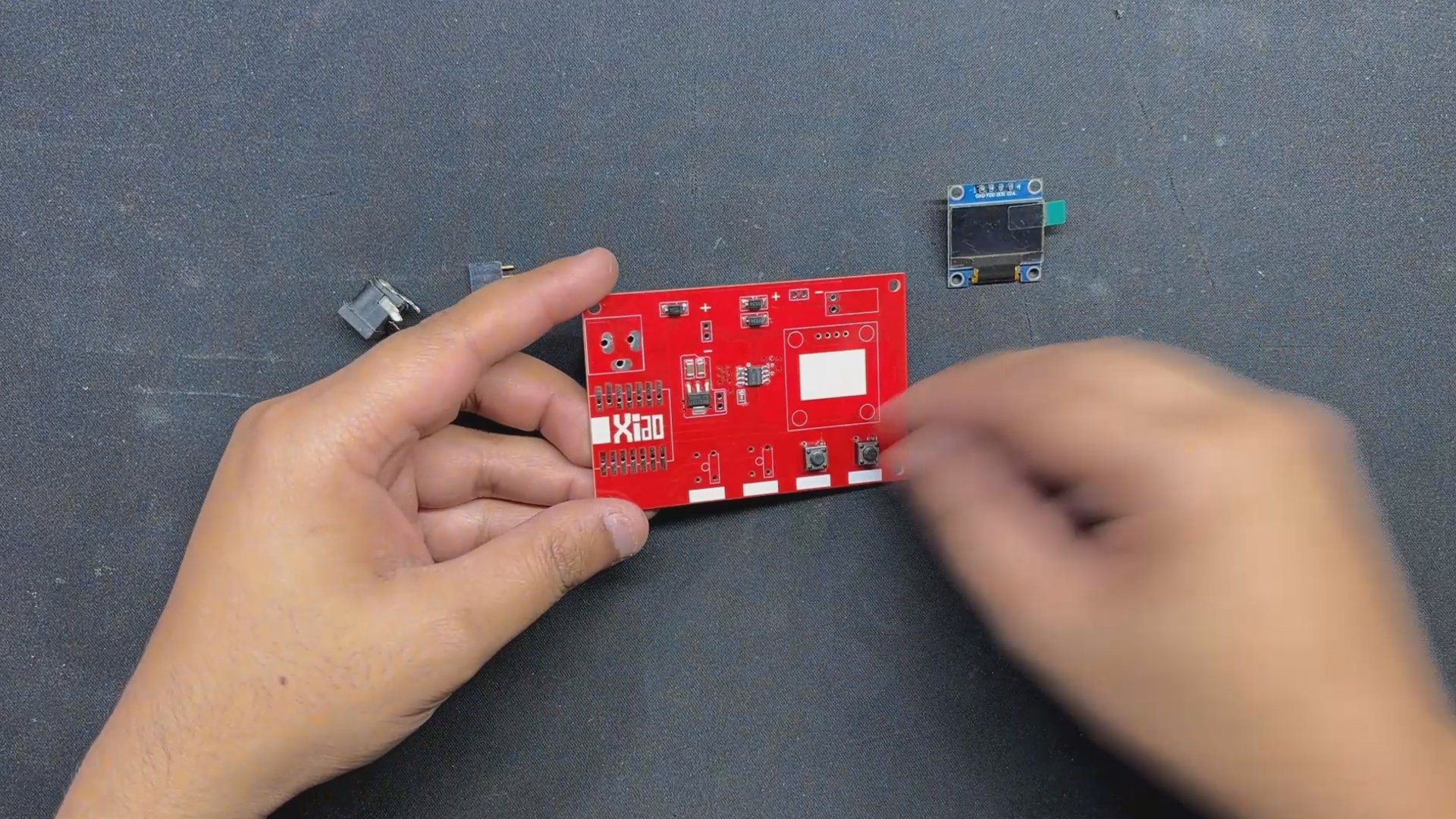
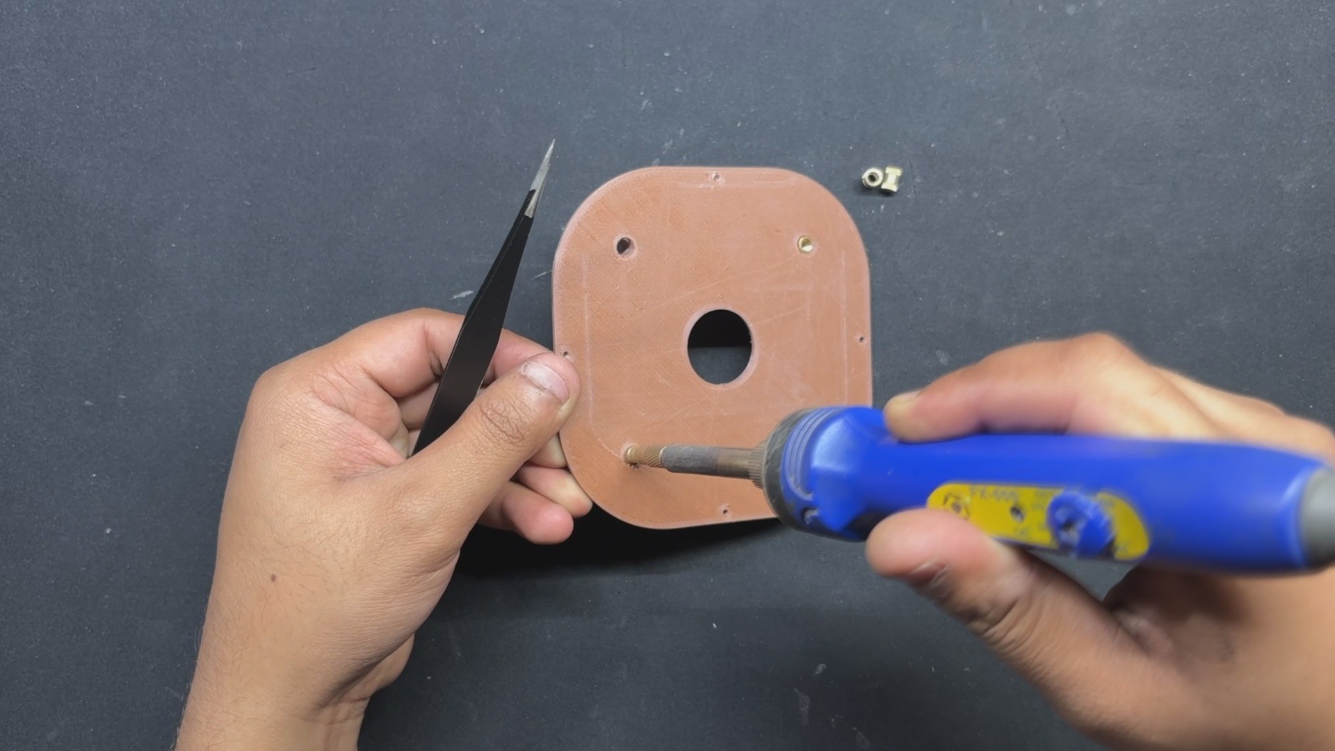
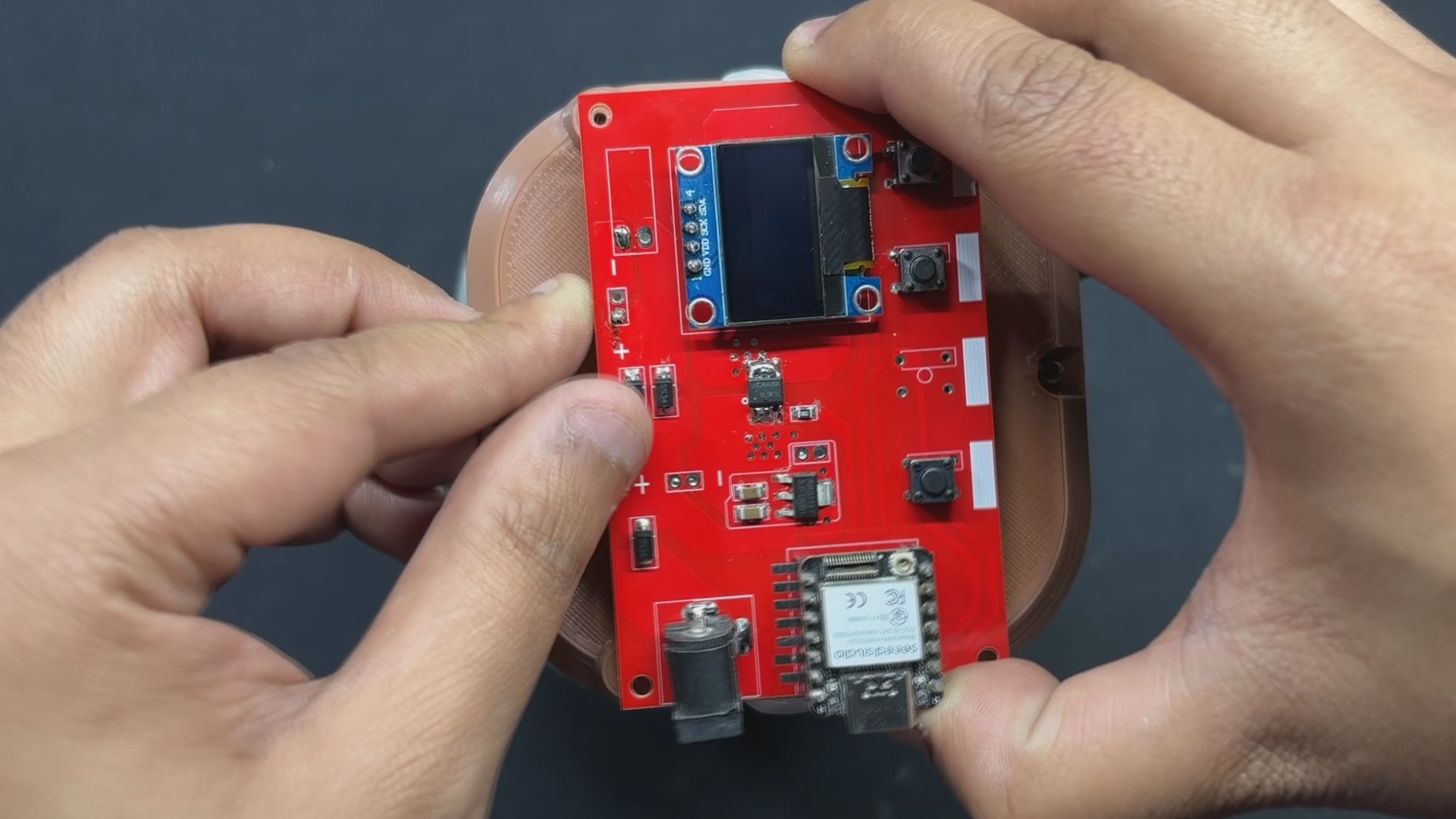
- We then replaced them with through-hole components such as push buttons, a CON7 header pin for the XIAO Dev board, a DC barrel jack connector, and an OLED display.
- The board is then flipped over, and all through-hole components and pads are soldered to the PCB with a soldering iron.
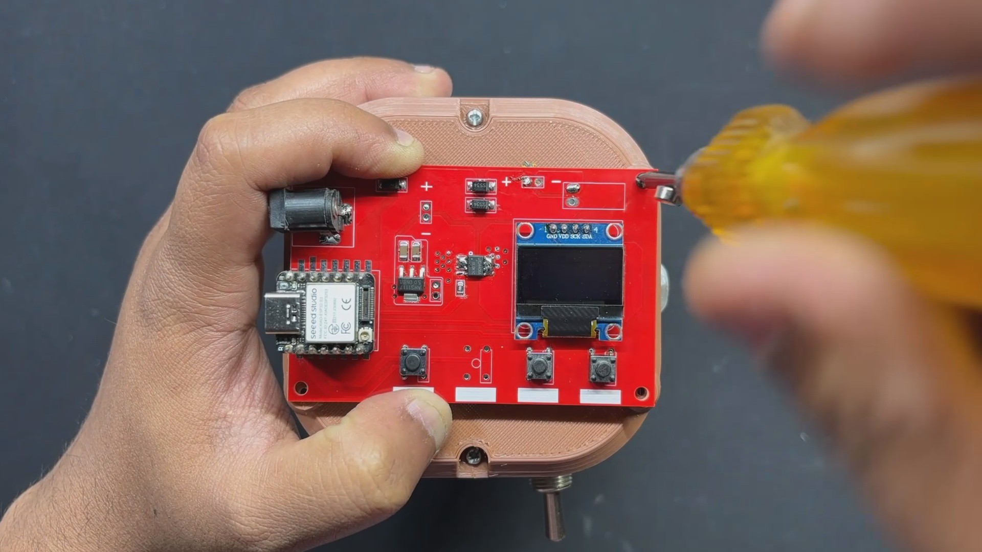
- Finally, we install the XIAO ESO32 S3 DEV Board over the CON7 Header Pin Connector.
-
2CODE
Now let's have a look at aour code and it's a simple one.
#include <Wire.h> #include <Adafruit_GFX.h> #include <Adafruit_SSD1306.h> // OLED display dimensions #define OLED_WIDTH 128 #define OLED_HEIGHT 64 #define OLED_ADDR 0x3C Adafruit_SSD1306 display(OLED_WIDTH, OLED_HEIGHT); // Define pins #define MOTOR_PIN D10 #define START_STOP_BUTTON_PIN D1 #define ADD_TIME_BUTTON_PIN D6 #define SUBTRACT_TIME_BUTTON_PIN D3 // Motor timer variables unsigned long motorRunTime = 60000; // Default 1 minute in milliseconds unsigned long timeAdjustment = 10000; // 10 seconds in milliseconds bool motorRunning = false; // Motor state unsigned long motorStartTime; // Button state tracking bool lastStartStopButtonState = HIGH; bool buttonPressed = false; bool lastAddTimeButtonState = HIGH; bool lastSubtractTimeButtonState = HIGH; void setup() { // Motor and button pins setup pinMode(MOTOR_PIN, OUTPUT); digitalWrite(MOTOR_PIN, LOW); // Ensure motor is off at startup pinMode(START_STOP_BUTTON_PIN, INPUT_PULLUP); pinMode(ADD_TIME_BUTTON_PIN, INPUT_PULLUP); pinMode(SUBTRACT_TIME_BUTTON_PIN, INPUT_PULLUP); // Serial communication setup Serial.begin(115200); // OLED display setup using your example method if (!display.begin(SSD1306_SWITCHCAPVCC, OLED_ADDR)) { // Initialize display Serial.println(F("SSD1306 allocation failed")); for (;;); // Halt execution if OLED fails } // Initial display output display.clearDisplay(); display.setTextSize(1); display.setTextColor(WHITE); display.setCursor(10, 20); // Adjust cursor for centering the single-line text display.println(F("Paper Mache Maker")); display.display(); delay(2000); // Hold the welcome screen for 2 seconds updateDisplay(); // Display the initial timer value } // Function to update the OLED display with the current time void updateDisplay() { display.clearDisplay(); display.setTextSize(2); display.setTextColor(WHITE); display.setCursor(5, 20); // Moved closer to the left display.print("Time: "); display.print(motorRunTime / 1000); // Time in seconds display.print("s"); display.display(); } void loop() { // Handle Start/Stop button bool currentStartStopButtonState = digitalRead(START_STOP_BUTTON_PIN); if (currentStartStopButtonState == LOW && lastStartStopButtonState == HIGH) { buttonPressed = true; // Button pressed } if (currentStartStopButtonState == HIGH && lastStartStopButtonState == LOW && buttonPressed) { motorRunning = !motorRunning; // Toggle motor state if (motorRunning) { motorStartTime = millis(); digitalWrite(MOTOR_PIN, HIGH); // Turn on motor Serial.println("Motor started."); } else { digitalWrite(MOTOR_PIN, LOW); // Turn off motor Serial.println("Motor stopped."); } buttonPressed = false; // Reset the flag } lastStartStopButtonState = currentStartStopButtonState; // Handle Add Time button bool currentAddTimeButtonState = digitalRead(ADD_TIME_BUTTON_PIN); if (currentAddTimeButtonState == LOW && lastAddTimeButtonState == HIGH) { motorRunTime += timeAdjustment; updateDisplay(); // Update the time on the display delay(50); // Debounce } lastAddTimeButtonState = currentAddTimeButtonState; // Handle Subtract Time button bool currentSubtractTimeButtonState = digitalRead(SUBTRACT_TIME_BUTTON_PIN); if (currentSubtractTimeButtonState == LOW && lastSubtractTimeButtonState == HIGH) { if (motorRunTime > timeAdjustment) { motorRunTime -= timeAdjustment; updateDisplay(); // Update the time on the display } else { Serial.println("Cannot reduce time below 0."); } delay(50); // Debounce } lastSubtractTimeButtonState = currentSubtractTimeButtonState; // Countdown Timer and Motor Off if (motorRunning) { if (millis() - motorStartTime >= motorRunTime) { motorRunning = false; digitalWrite(MOTOR_PIN, LOW); // Turn off motor Serial.println("Motor stopped automatically after timeout."); updateDisplay(); // Reset display after timeout } else { unsigned long timeLeft = (motorRunTime - (millis() - motorStartTime)) / 1000; display.clearDisplay(); display.setTextSize(2); display.setTextColor(WHITE); display.setCursor(5, 20); // Timer display moved closer to the left display.print("Time: "); display.print(timeLeft); display.print("s"); display.display(); } } } -
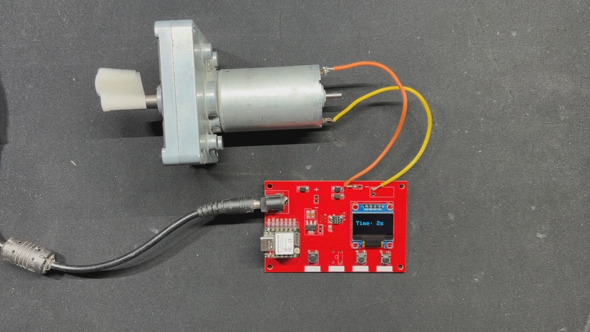
3MOTOR TEST
![]()
![]()
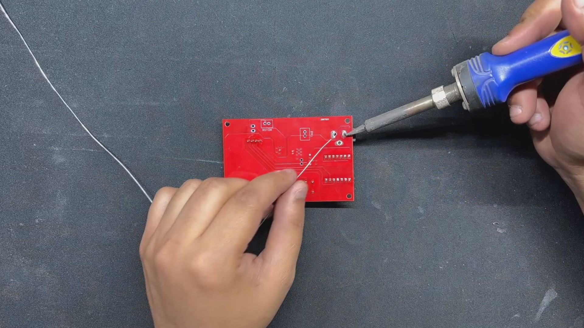
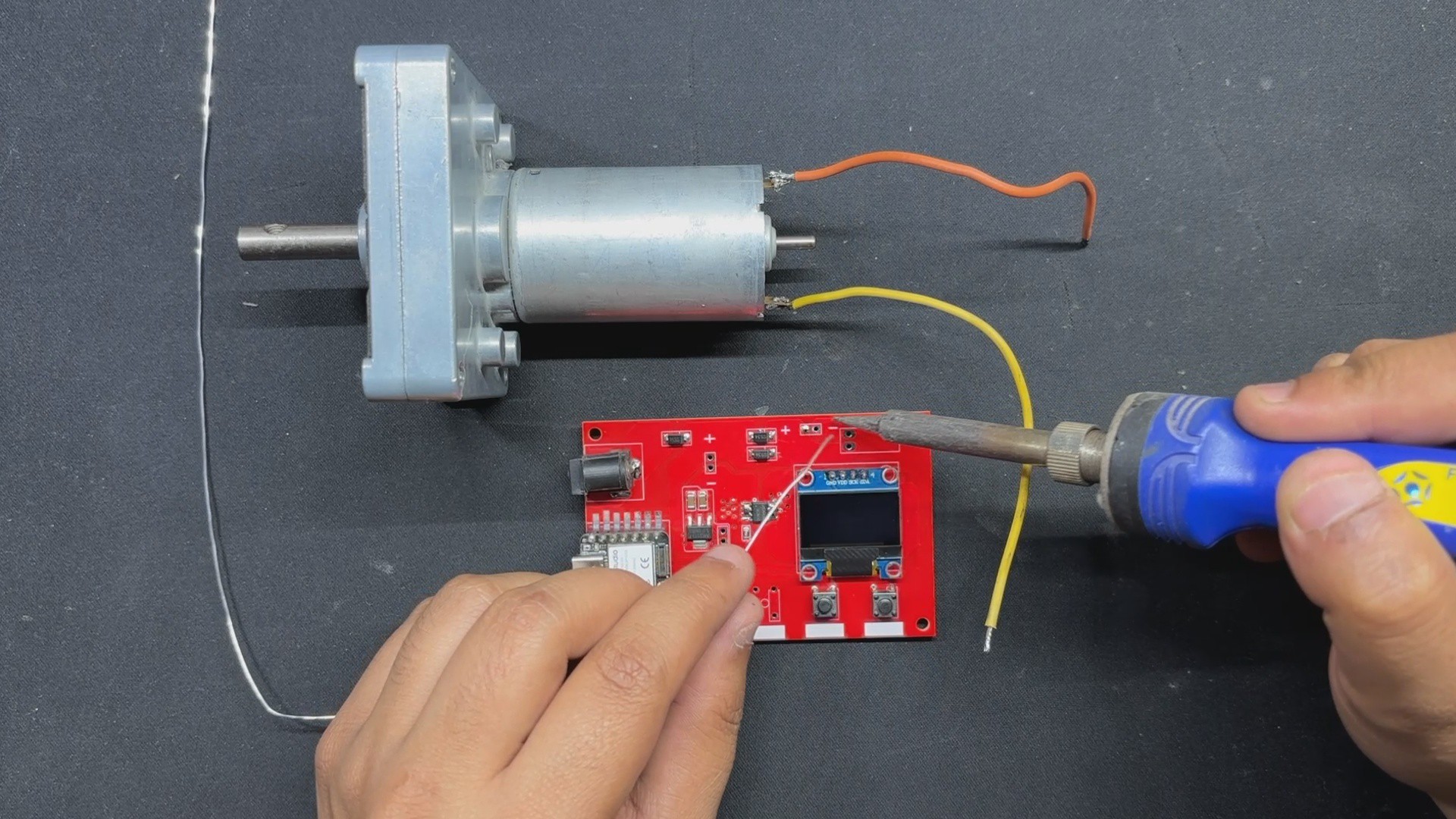
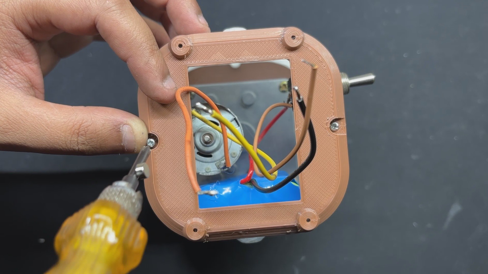
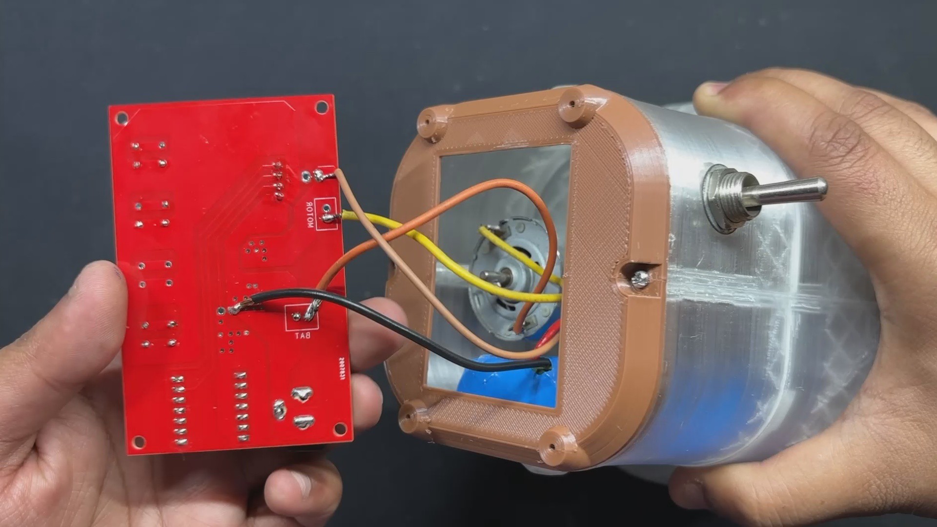
After uploading code to our Motor Driver board, we used a soldering iron to connect a 12V Gear Motor to our Circuit's Motor connector.
A 12V power supply is linked via the onboard Barrel DC connector.
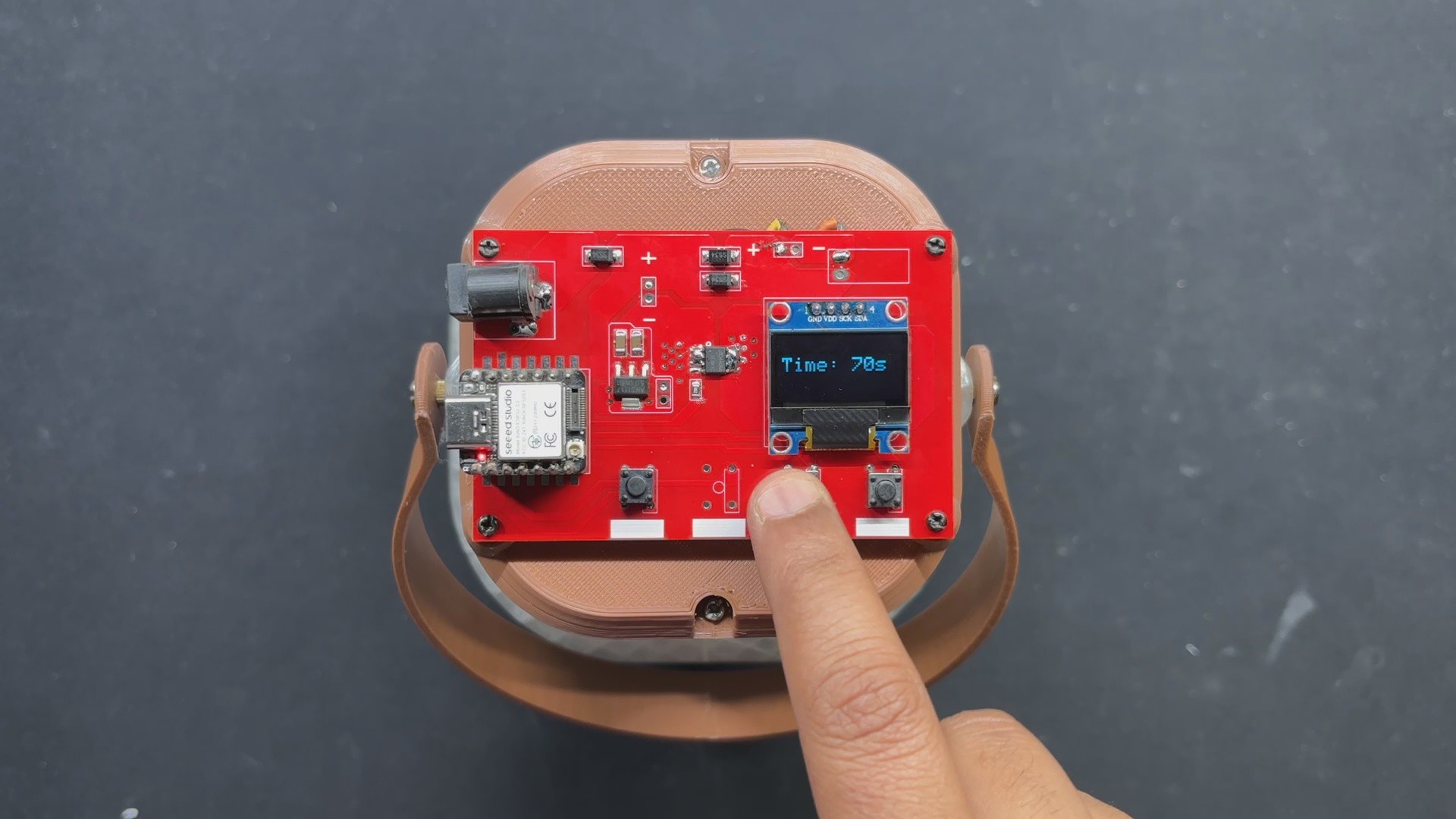
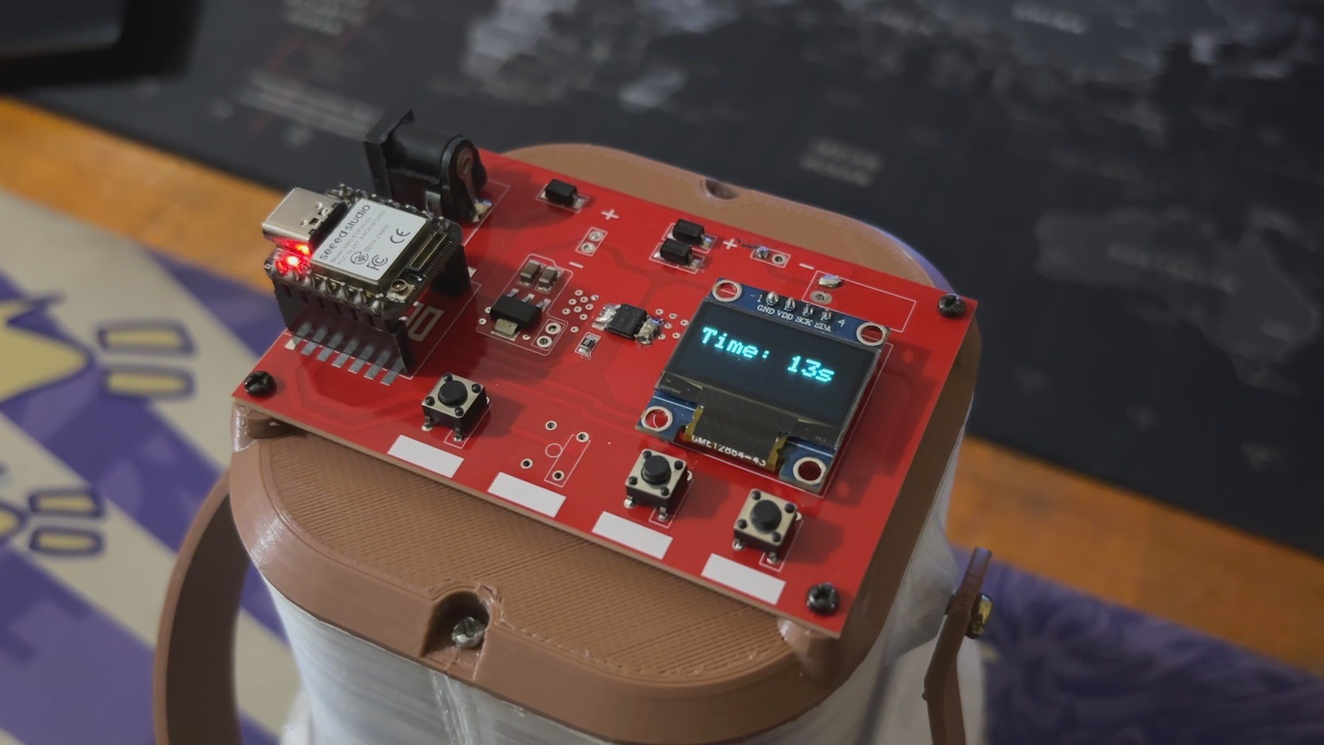
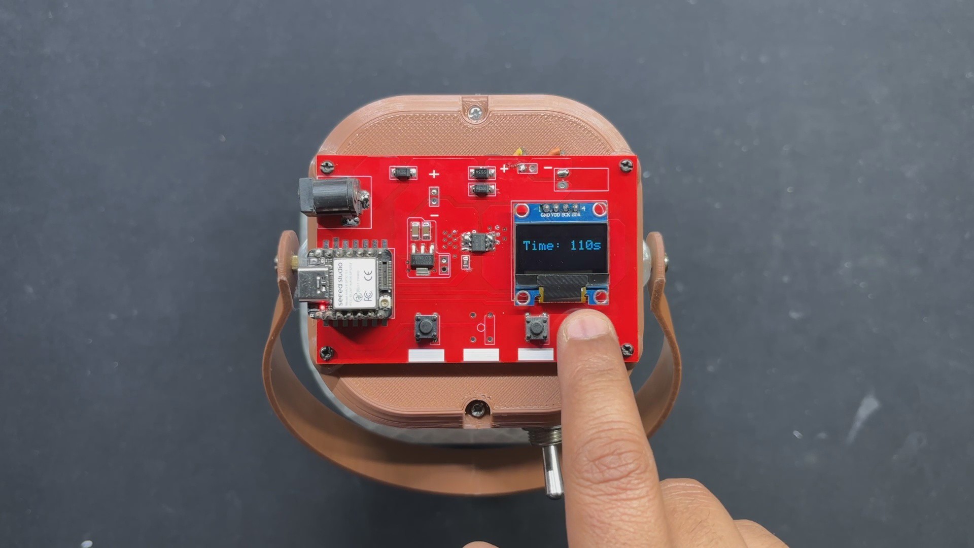
We set the run time using the Timer+ and Time- buttons, which is displayed on the LCD screen, and the motor begins to rotate when we push the Start/Stop button.
This demonstration confirms that our setup is operational, and we can now proceed to the body assembly procedure.
-
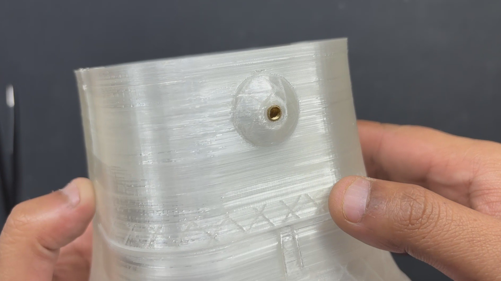
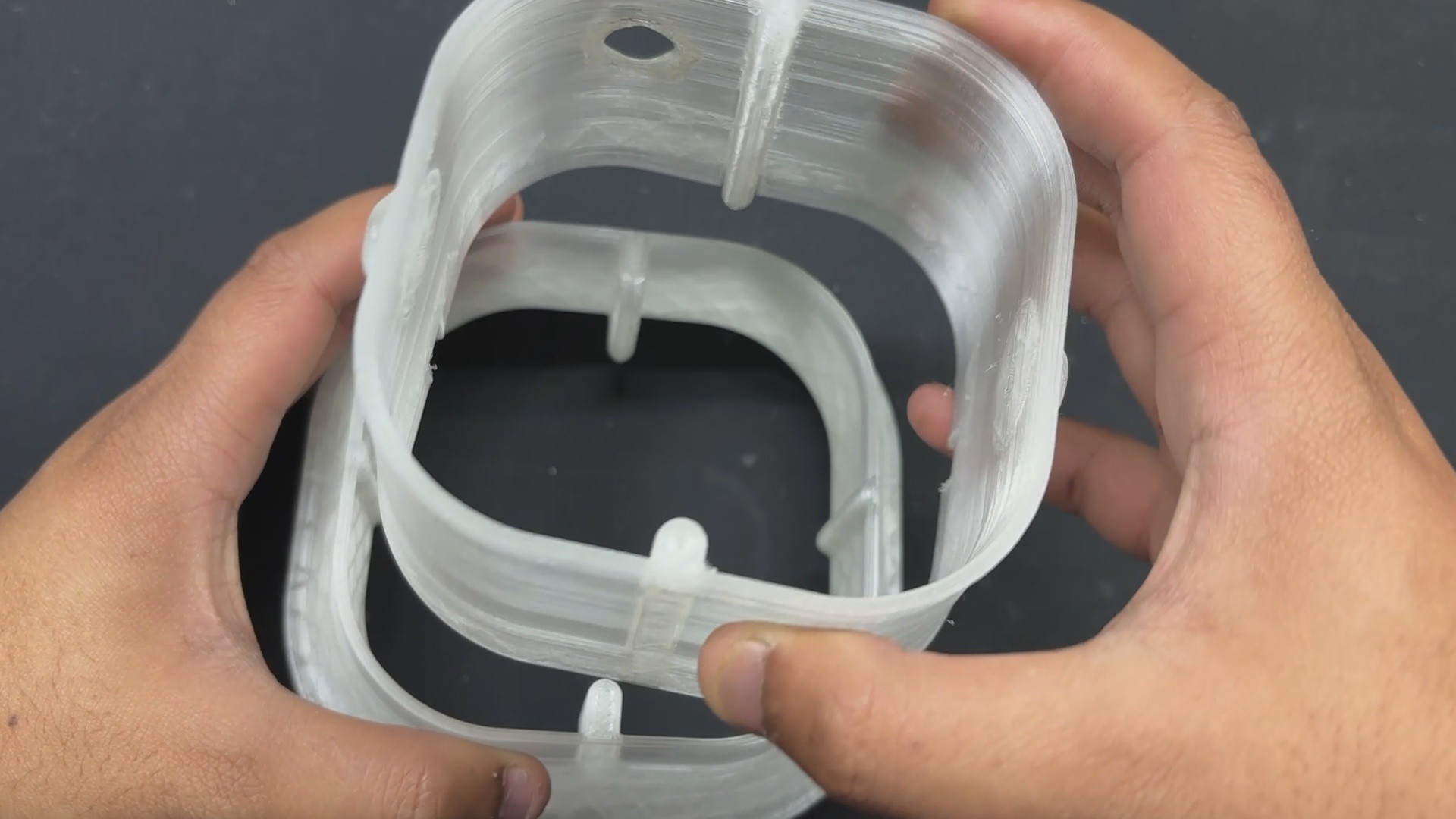
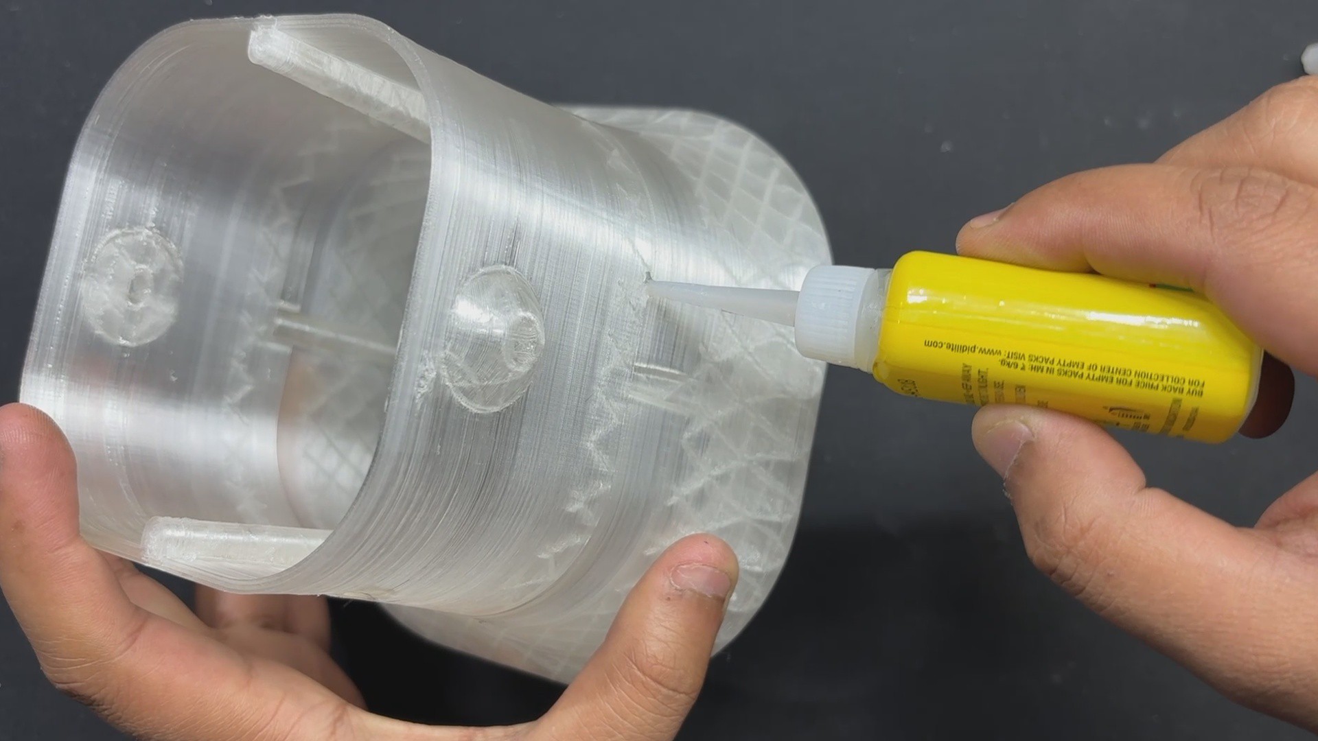
4BASE BODY ASSEMBLY
![]()
![]()
![]()
![]()
![]()
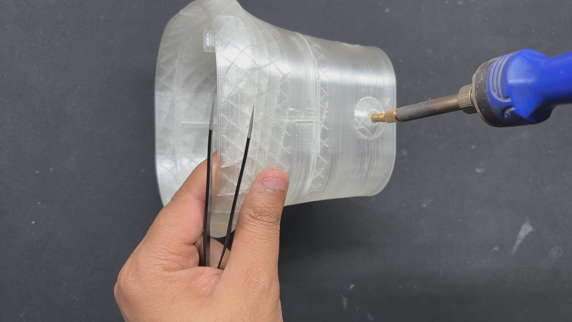
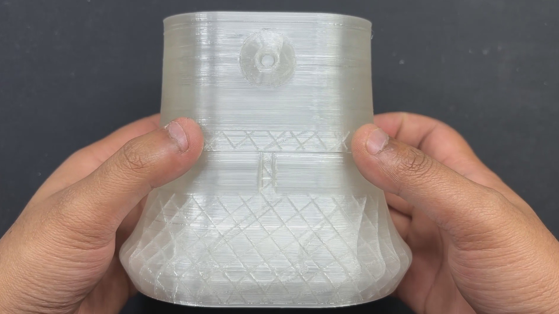
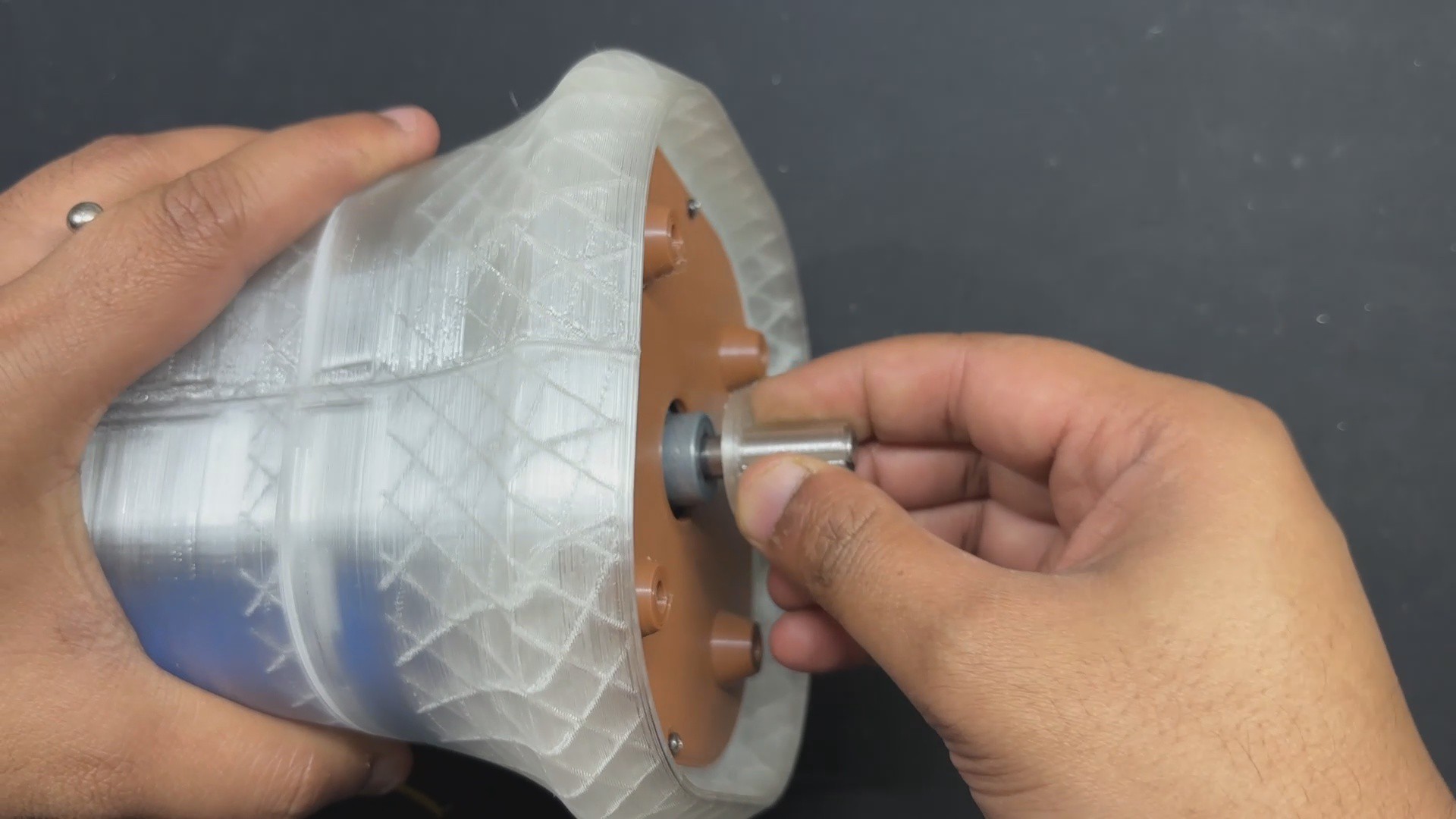
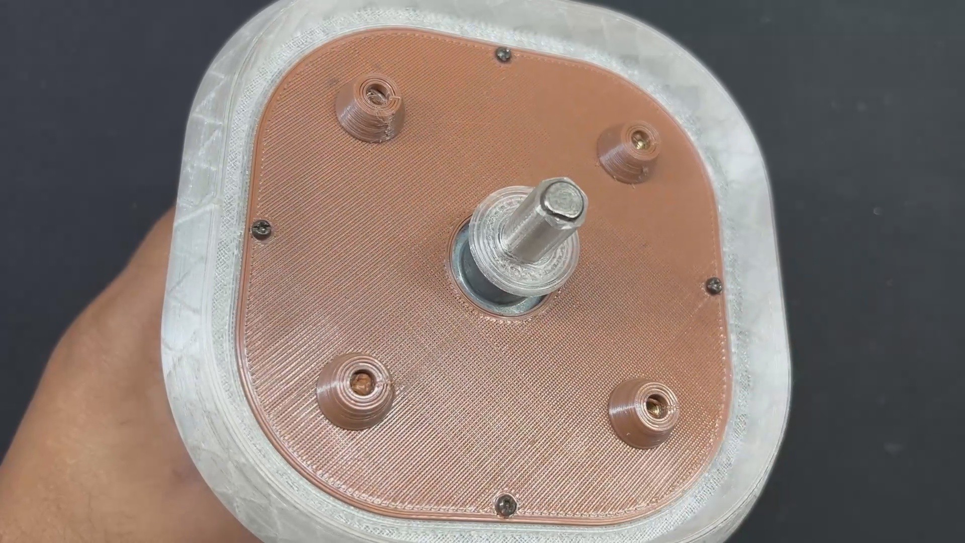
- We begin the body assembly procedure by joining the two main body pieces that were printed separately by placing the upper portion over the bottom part and then permanently securing both of them with superglue.
- We inserted M3 threaded inserts into the two holes on the left and right faces of the base body. We use our soldering iron in conjunction with a Threaded insert holding kit to heat the threaded insert until it slides into its position by melting the plastic surrounding it.
-
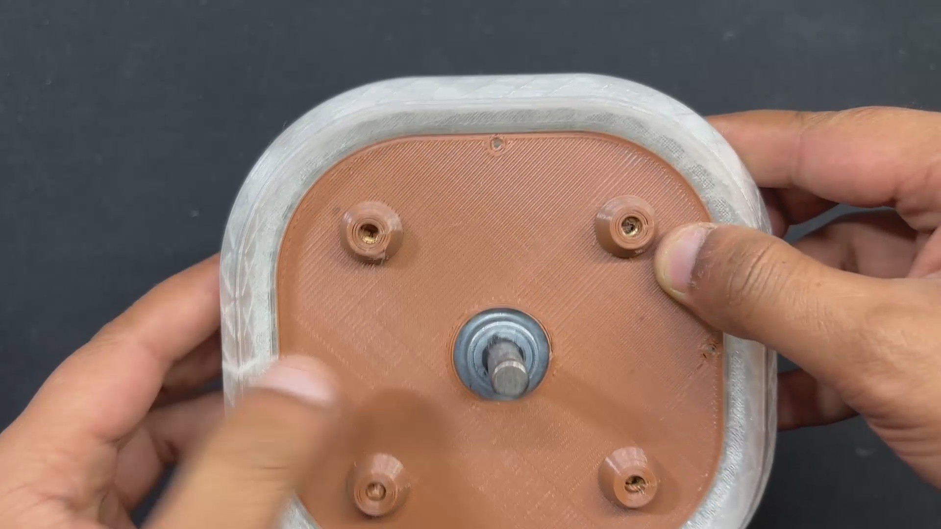
5MOTOR HOLDER ASSEMBLY
![]()
![]()
![]()
![]()
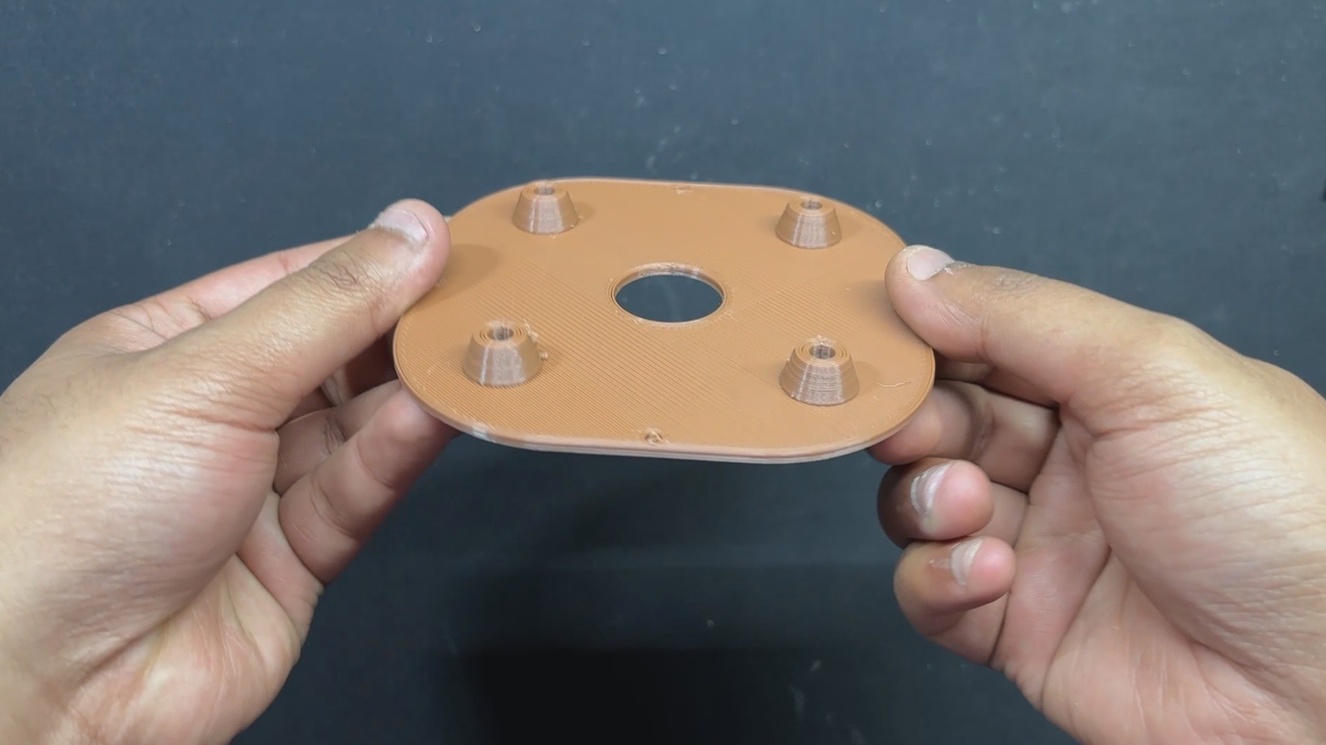
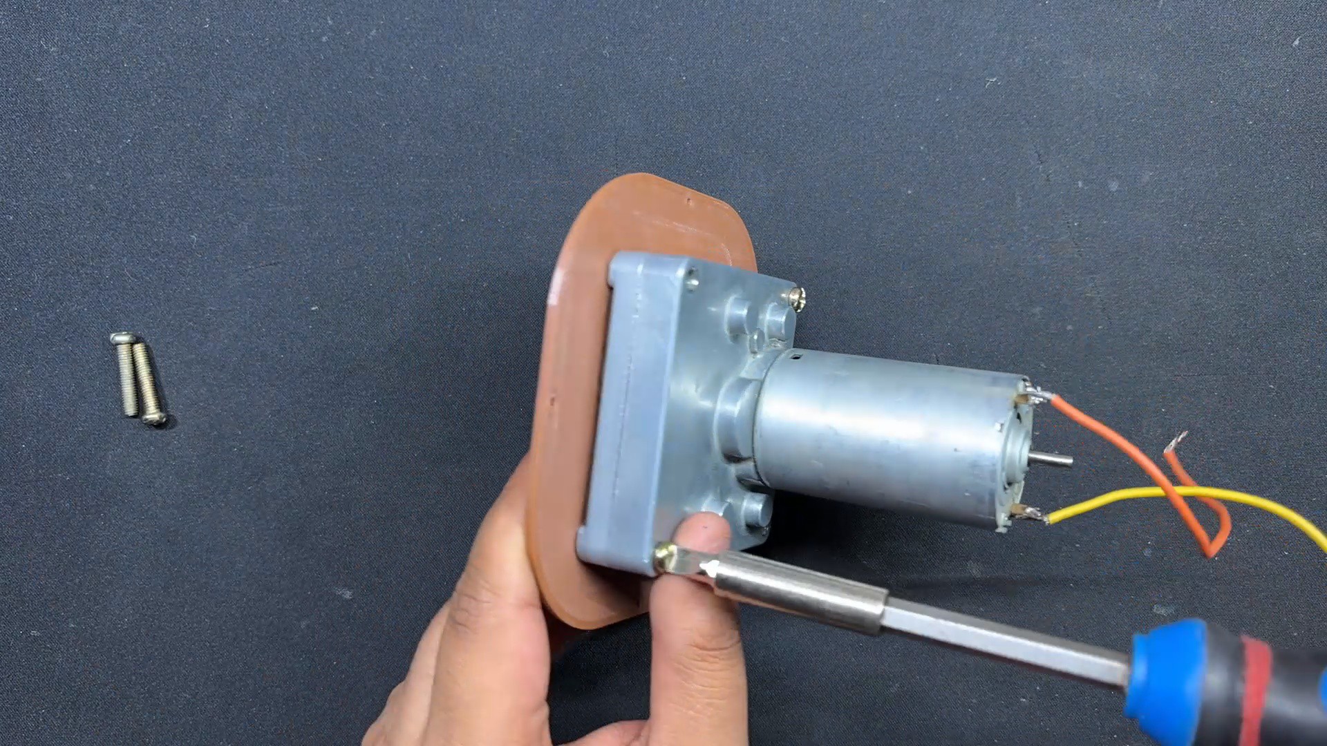
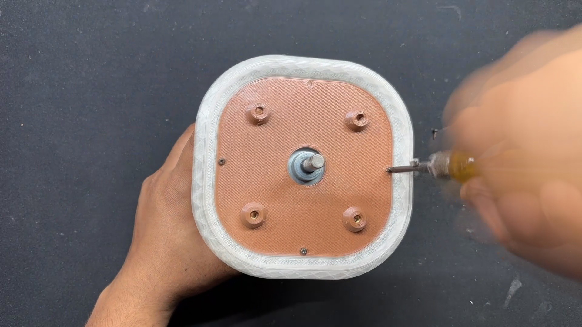
- We now begin the motor holder assembly by inserting four M3 threaded inserts into the holes we modeled on the part. These threaded inserts will be used to mount the gear DC motor to this part.
- We begin by placing the insert over the hole, then using the soldering iron to press it down. The insert will melt the plastic around it and slide down into position. We do this for four inserts.
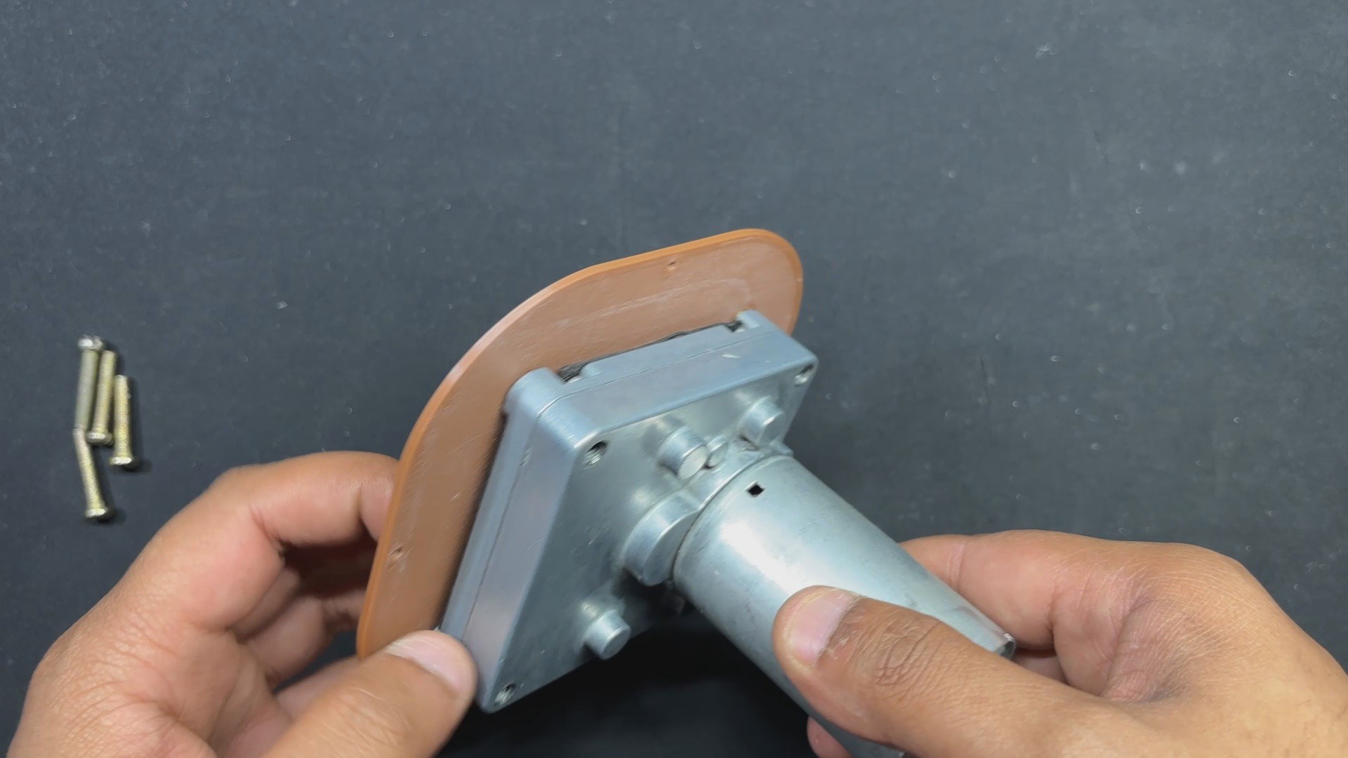
- Next, we align the mounting holes on the Gear DC Motor and secure it to the Holder part with four M3 bolts.
-
6BASE BODY-MOTOR HOLDER ASSEMBLY
![]()
![]()
![]()
![]()
![]()
![]()
![]()
- The Motor Holder Assembly is now attached to the base body's bottom side, and we utilize Four m2 screws to secure both the base body and the Holder assembly together.
- The Lever Switch is now placed in its proper position and secured with the locking nut that came with it.
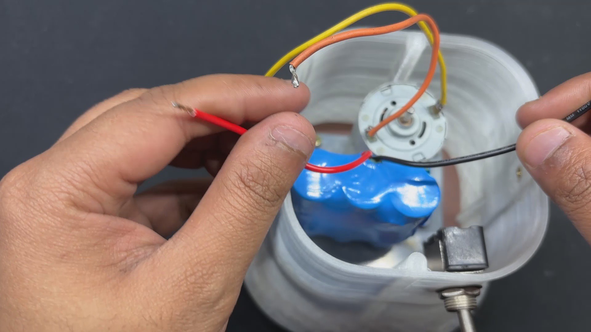
- The 12V Lithium Battery Pack is now lowered down inside the Base Body, exactly next to the Gear motor.
- The battery pack's VCC is attached to the switch's NC terminal, and an additional wire is soldered to the switch's NO terminal. We inserted the switch between the battery's VCC and the circuit to disconnect the main power.
- We use hot glue to keep the battery lock in place.
-
7BLADE ADAPTOR
![]()
![]()
![]()
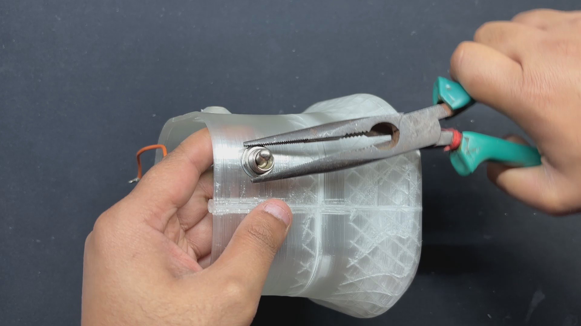
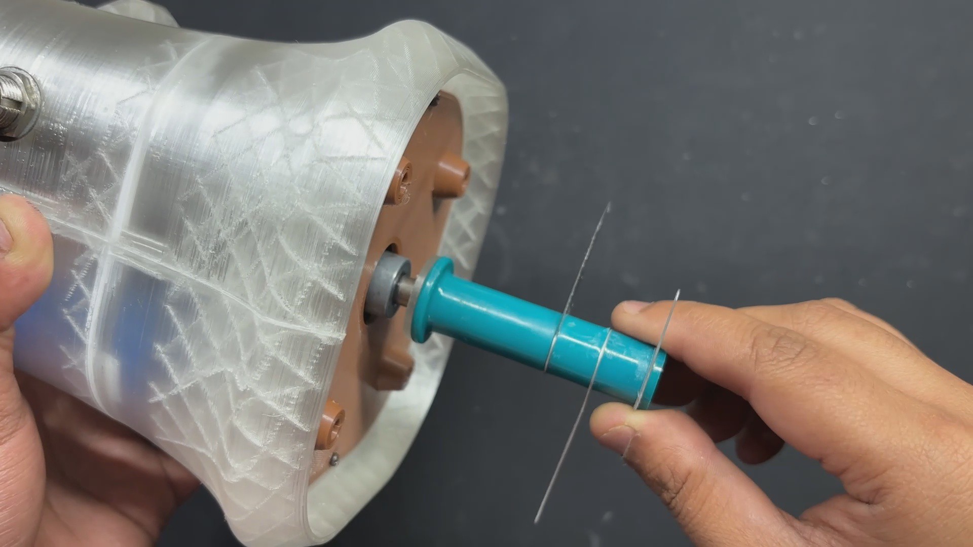
Because the Blade part we're using has a hexagon-shaped mounting slot and the motor we're using has a D shaft, we had to design a part that will work as an adapter to link the motor's D shaft to the Blade's hexagon slot.
This adapter part is first attached to the motor's shaft, and then the blade section is placed on it.
Next, we attached the Jar, which keeps the Blade section locked in place and allows it to only rotate in place.
-
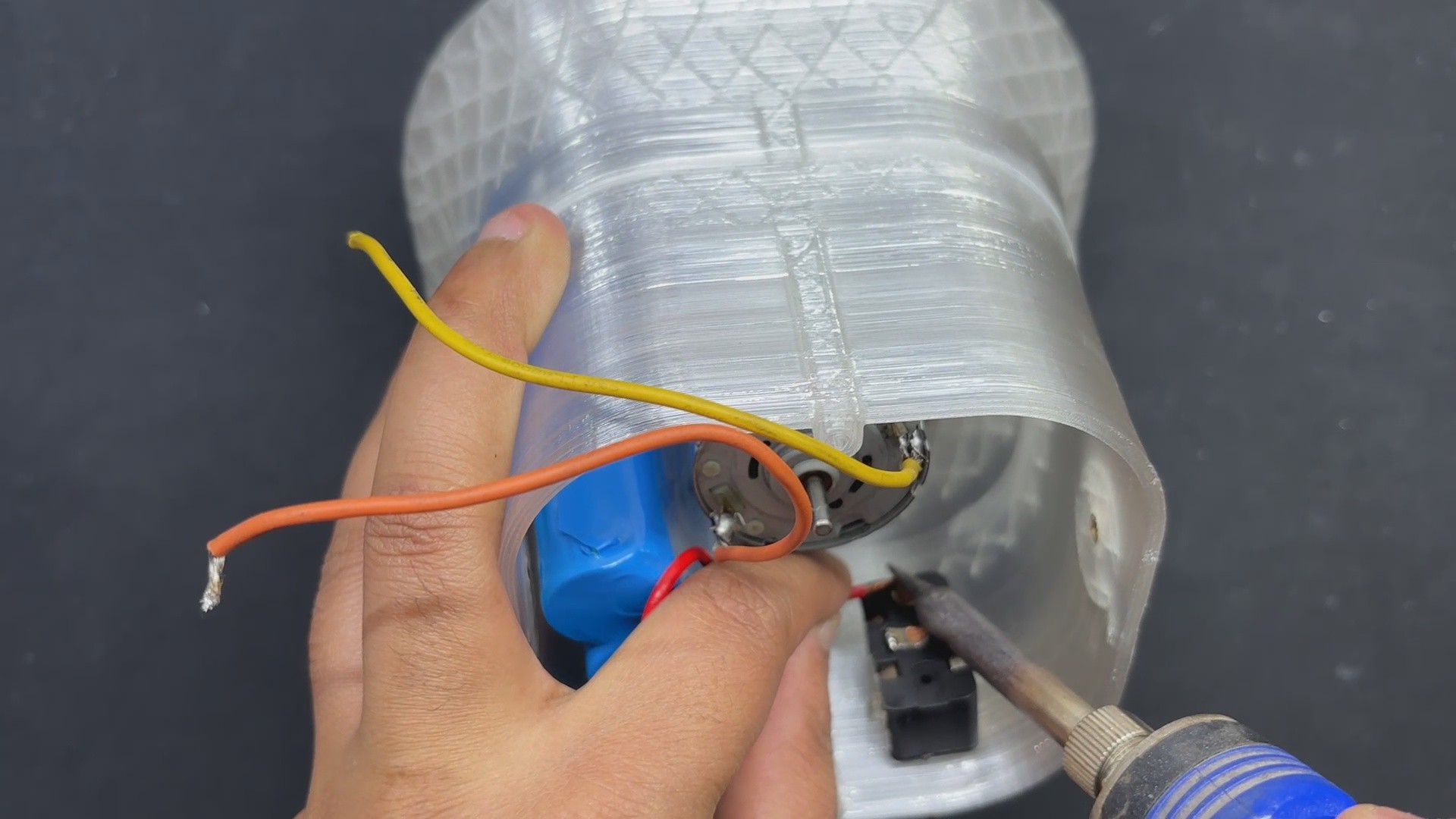
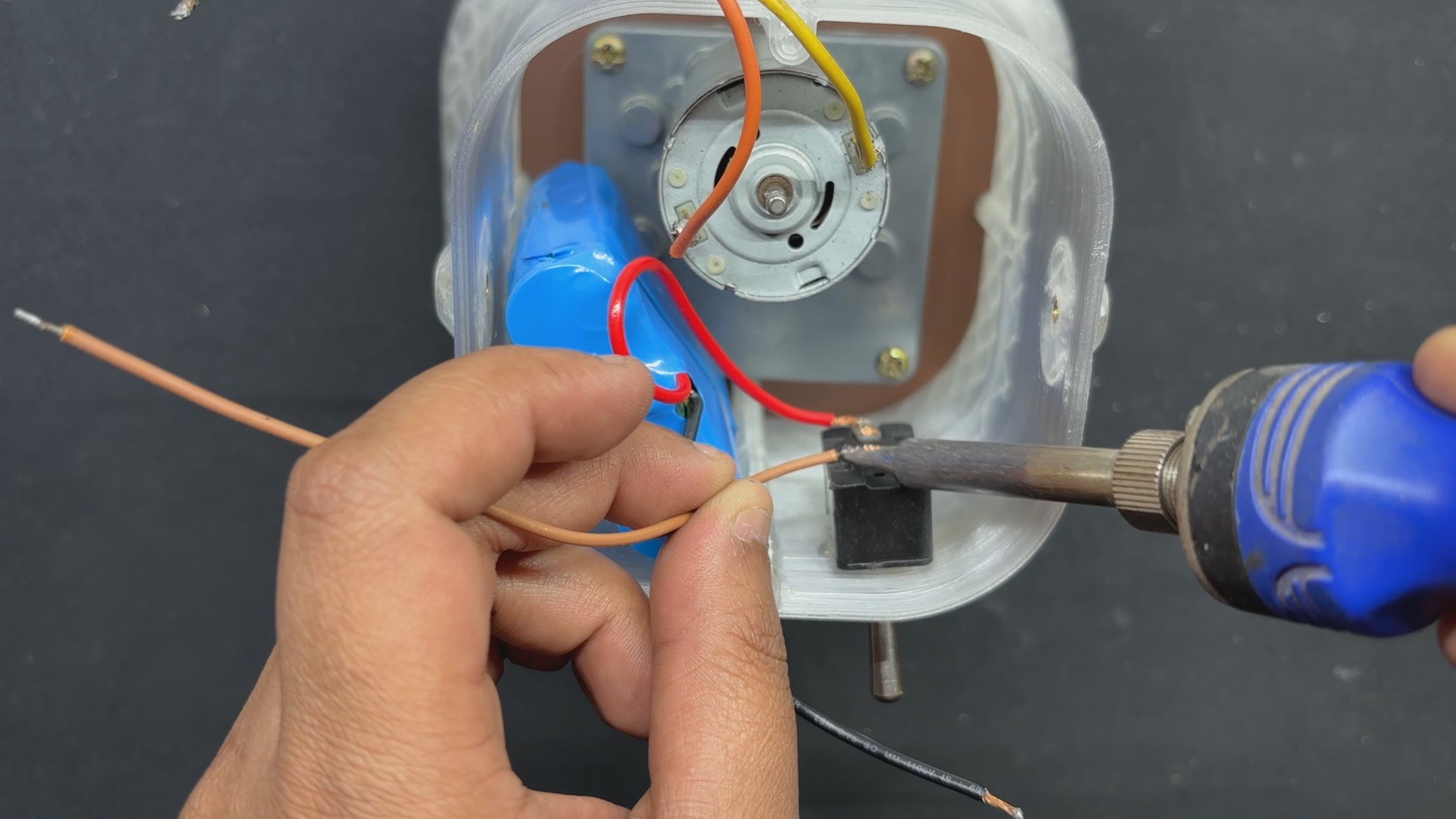
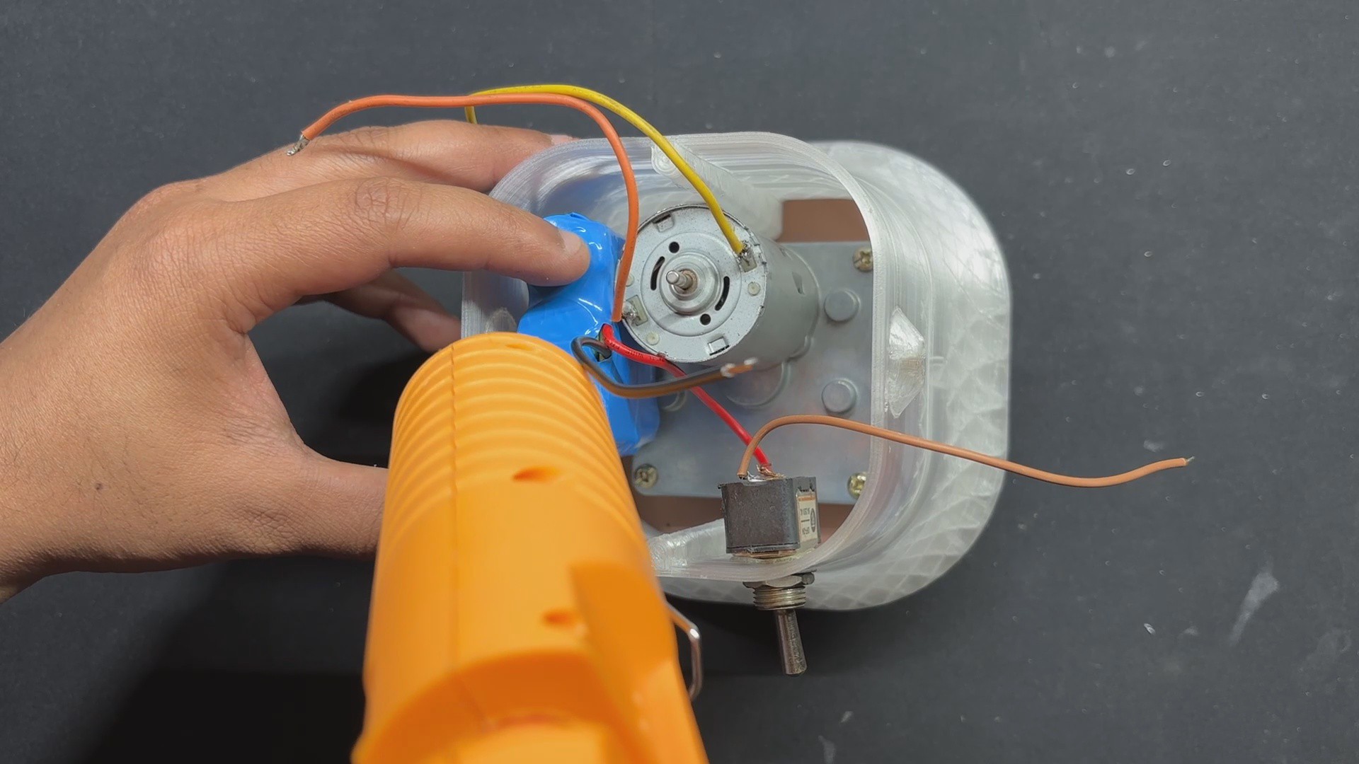
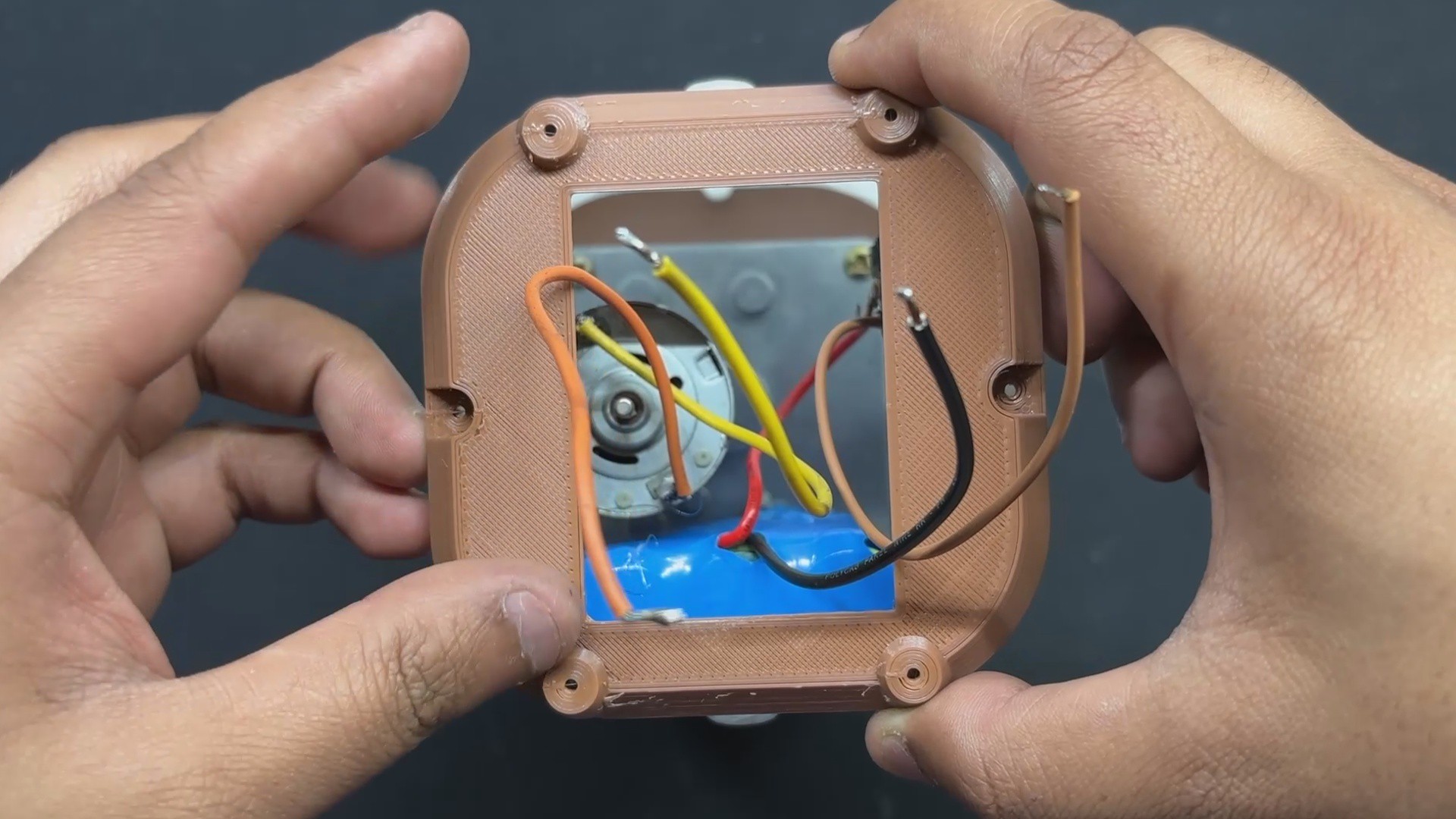
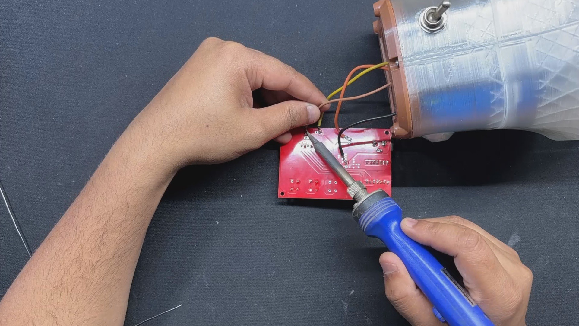
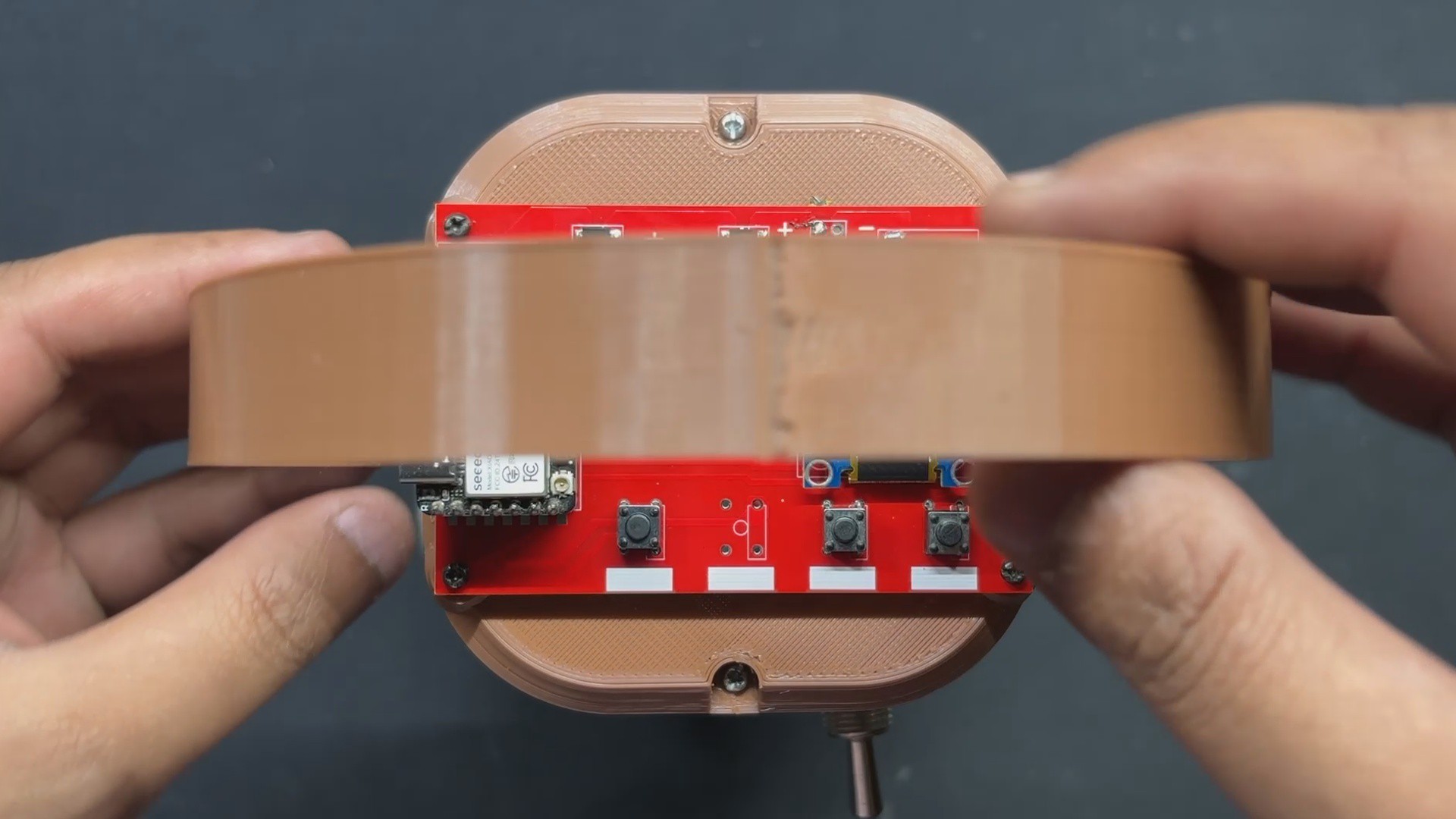
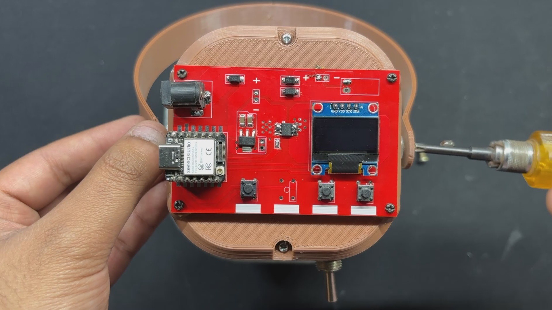
8LID & CIRCUIT ASSEMBLY
![]()
![]()
![]()
![]()
![]()
![]()
- The Lid Part is now positioned over the base body, and all cables, including the battery and motor wires, are routed via the Lid Part's rectangular opening.
- The lid is then secured to the base body with two M2 screws.
- We next used a soldering iron to connect the battery terminals that were positive from the switch and GND to the circuit's battery terminals. We then connected the motor terminals to the circuit's motor terminal.
- All wires are then tucked within, and the circuit board is positioned over the mounting screw bosses. We then use four m2 screws to secure Circuit to the Lid part.
-
9HANDLE ASSEMBLY
![]()
![]()
Finally, we place the Handle and secure it to the Base Body with two M3 Bolts.
This completes the assembly process, and our device is now ready.
-
10RESULT
![]()
![]()
![]()
![]()
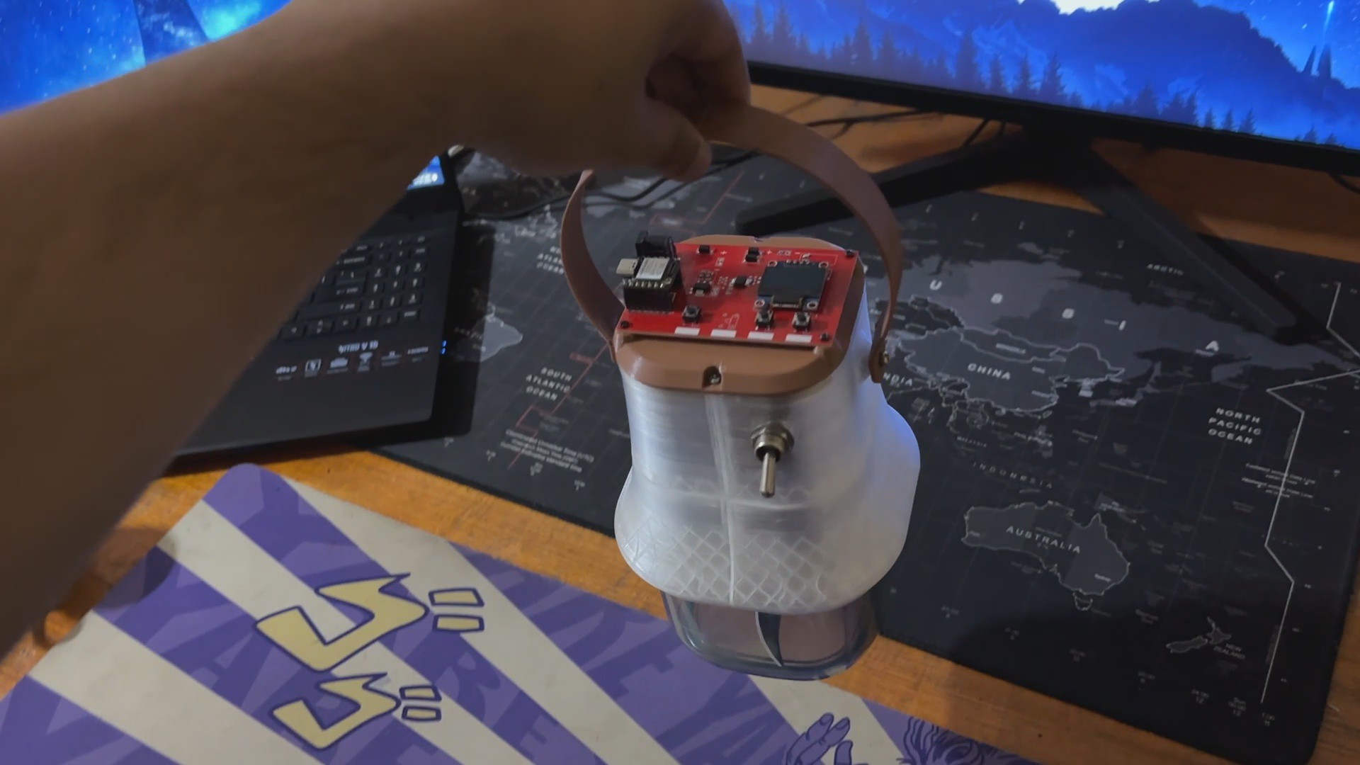
This is the end result of this small but useful build, PulpPro, a DIY Paper Mache making machine that converts paper into pulp using a cutting blade powered by a DC Gear motor.
To use this device, we first turn on the Lever switch, which powers the device. Once powered on, we are greeted with a Paper Mache Machine welcoming screen and a timer of 60 seconds is displayed. We have set the Default Run Time to 60 seconds.
The Time + and Time - buttons allow the user to increase or reduce the 60-second default time. After selecting the time parameters, we may start the device by hitting the Start/Stop button, which will start the motor at the specified run time. The timer begins as soon as the device is turned on and the motor begins to rotate.
PulpPro
Made a Paper Maché Machine from scratch using 3D-printed parts and a custom circuit.
Discussions
Become a Hackaday.io Member
Create an account to leave a comment. Already have an account? Log In.