Rory
Rory-
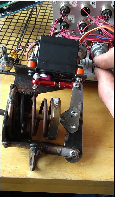
Hobby Servo Wastegate Actuator
10/12/2017 at 10:05 • 0 commentsI wanted to be able to control the wastegate via a servo driven via my engine controller. Normally the wastegate is operated via a pneumatic diaphragm directly from the inlet pressure. This doesn’t give you much scope to easily change the pressure setpoint however. After market 'boost controllers' are available which use a solenoid valve to bleed off some of the pressure sent to the actuator. This only give you the facility to raise the pressure setpoint over stock. I wanted the ability to lower the pressure setpoint during initial testing/tuning.
I brought a Turnigy TGY-1501MG servo rated at 15Kg/cm to do some testing. I chopped up a sab 9-3 wastegate actuator for the spring, spring seats and shaft and welded up a new bracket. My old meccano set came to the rescue providing a roller for the top of the spring seat.
![]()
The actuator worked quite well although I think this application is at the limits of the servo's torque capacity. The holding current is quite high which may cause overheating. The servo is controlled via a PWM signal from an arduino in my engine controller. Will test when I have the turbo installed on the car.
-
Intake Tubing Finished
10/12/2017 at 09:38 • 0 commentsLong time since the last update as usual. Much has been happening however.
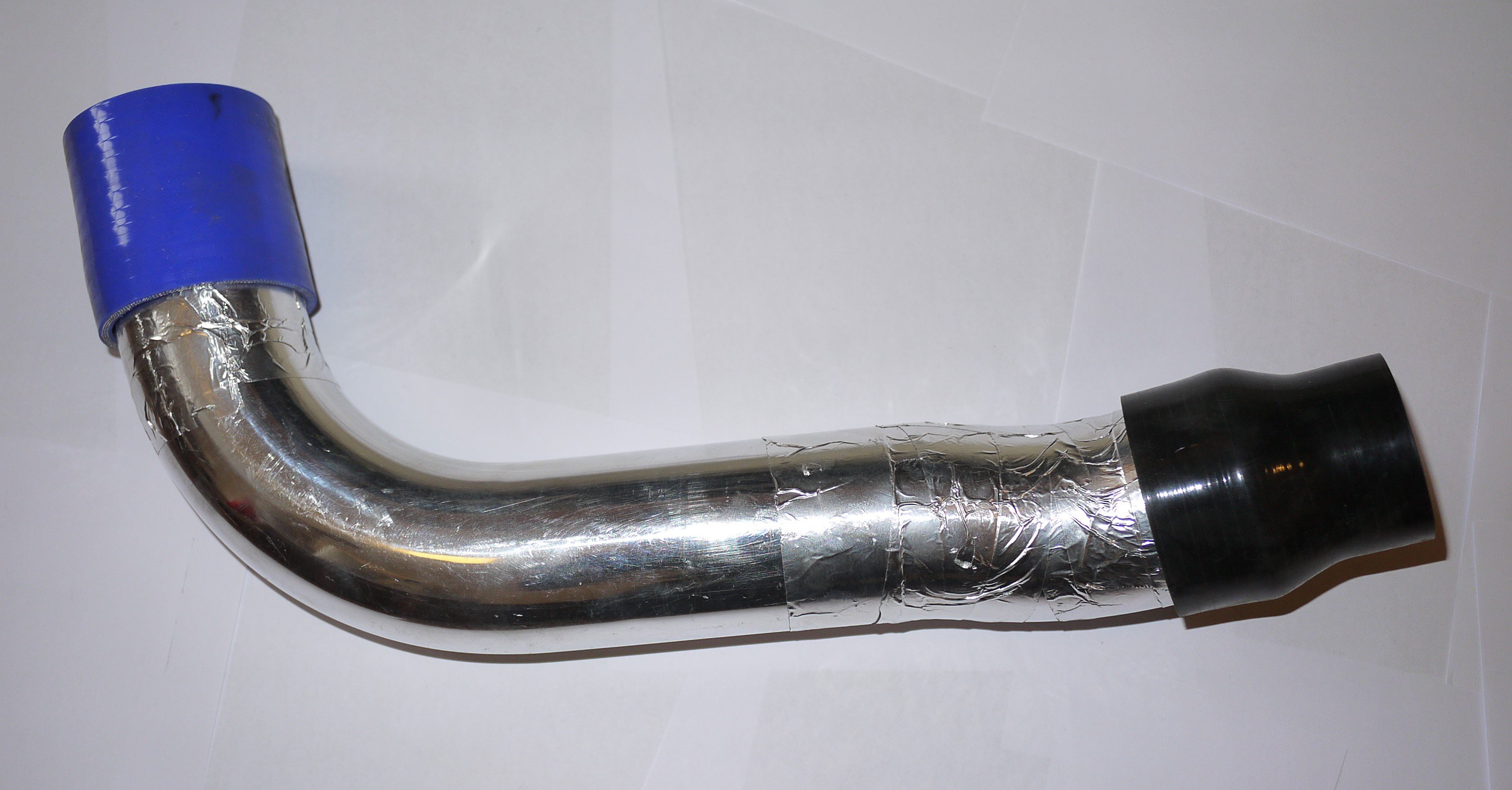
I have finished routing and welding up the intercooler tubing. In hindsight it would have been better to use 2'' tubing rather than the 2.5'. Some of the clearances were very tight, particularly around the ancillary belt pulleys around the right-hand side of the engine. the 2.5'' does match the throttle body inlet though which was nice.
I had heard bad things about these eBay tubing kits on the internet in that the aluminium was poor quality and very hard to weld. Initially I did struggle, however this was due to my welding setup. After a fair bit of messing about I settled on the following settings:
Current - 45 to 55A depending on how cold the part was, weld position etc.
Frequency - 180Hz with 40% cleaning
Electrode - 1.6mm Ceriated. This made a massive difference over the 2.4mm I started with
Filler - 5356 1.6mm. I tried to use 2.4 mm originally with not much luck
Gas - Set your shielding gas correctly. There are a few guides on the net about it. This was absolutely critical. A high flow rate introduces turbulence around the shroud introducing oxygen resulting in a horrible weld.
I had really got the hang of it by the end of the job. Don’t let anyone tell you tigging thin aluminium is impossible without professional tuition or years of experience!
The tubing kit was good value, I used absolutely all the bends, nothing left!
Herse a bad photo of the parts prior to fitting
![]()
-
Long Time Since Last Update
08/07/2017 at 17:54 • 0 commentsLong time since may last update. Been busy with other things but I have been able to push the project forward in the last few weeks.
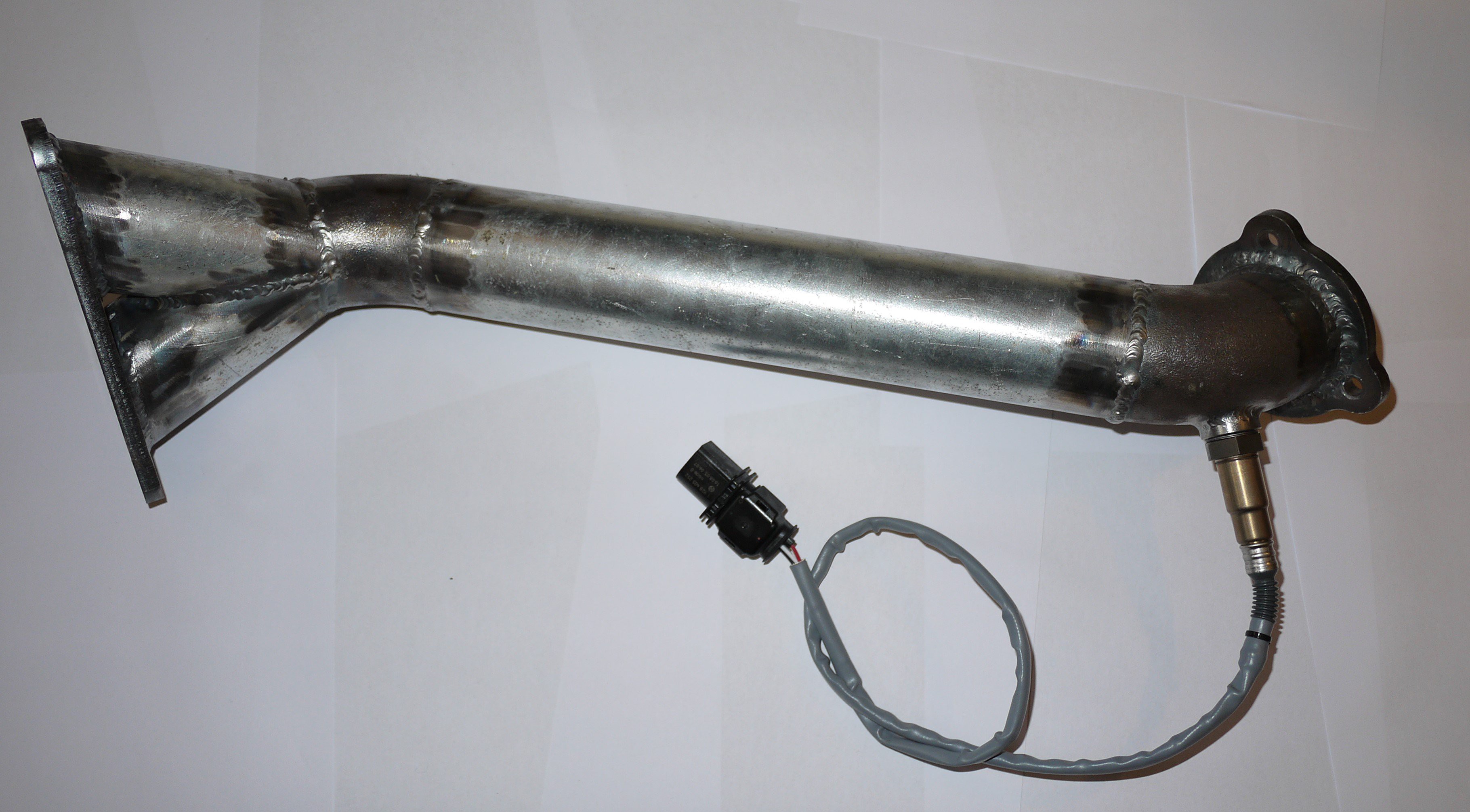
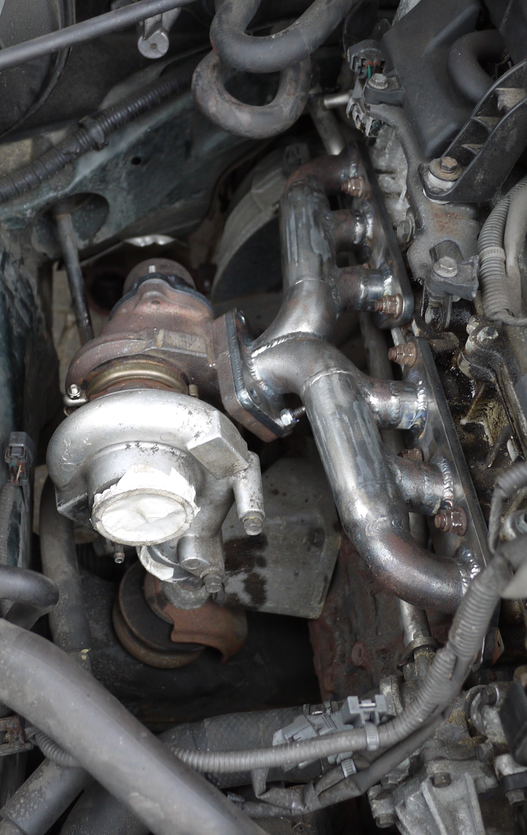
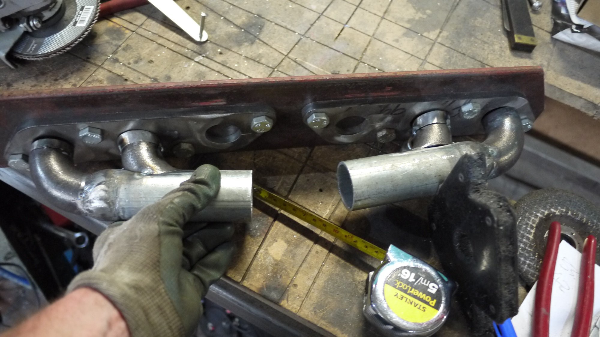
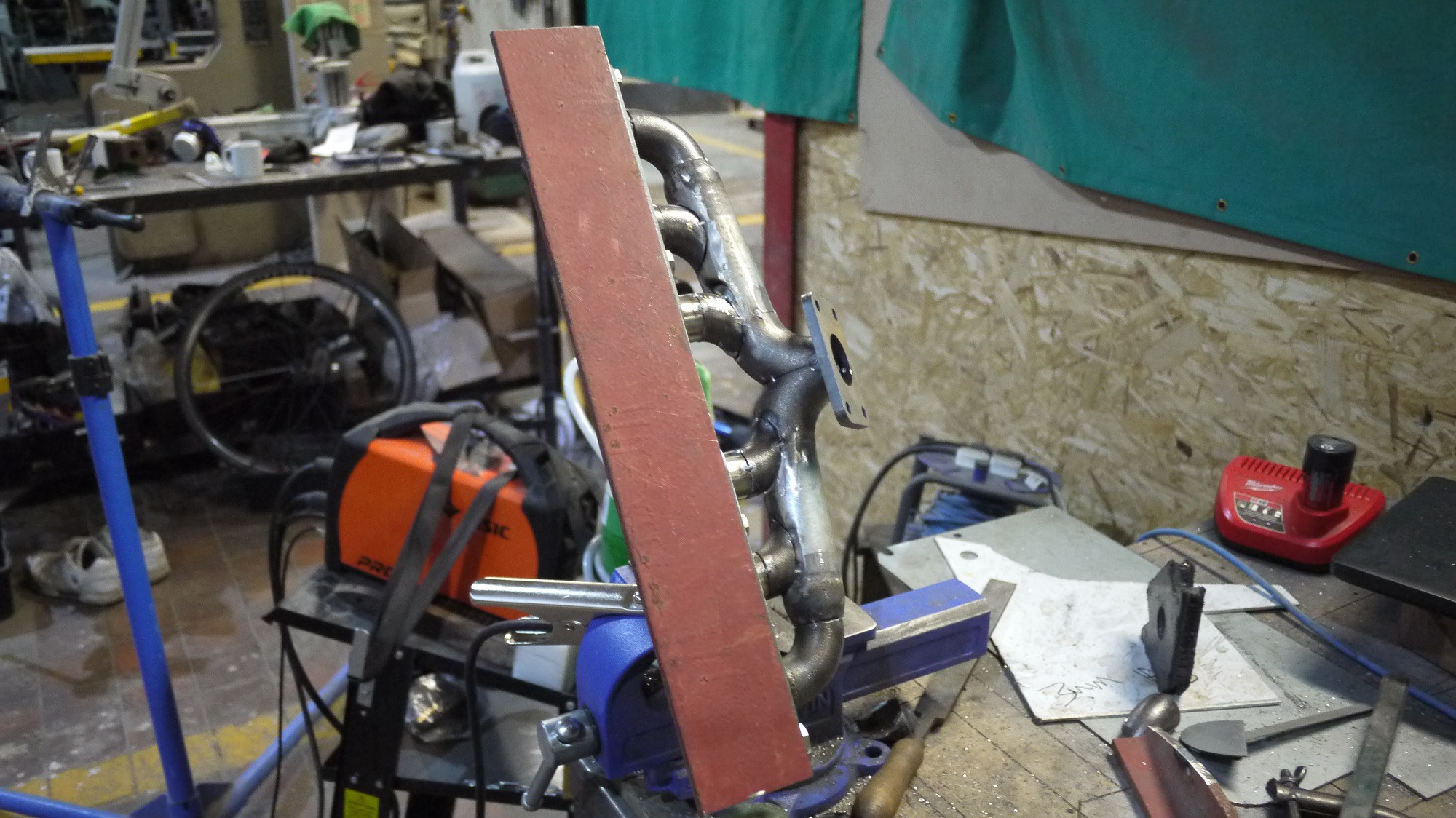
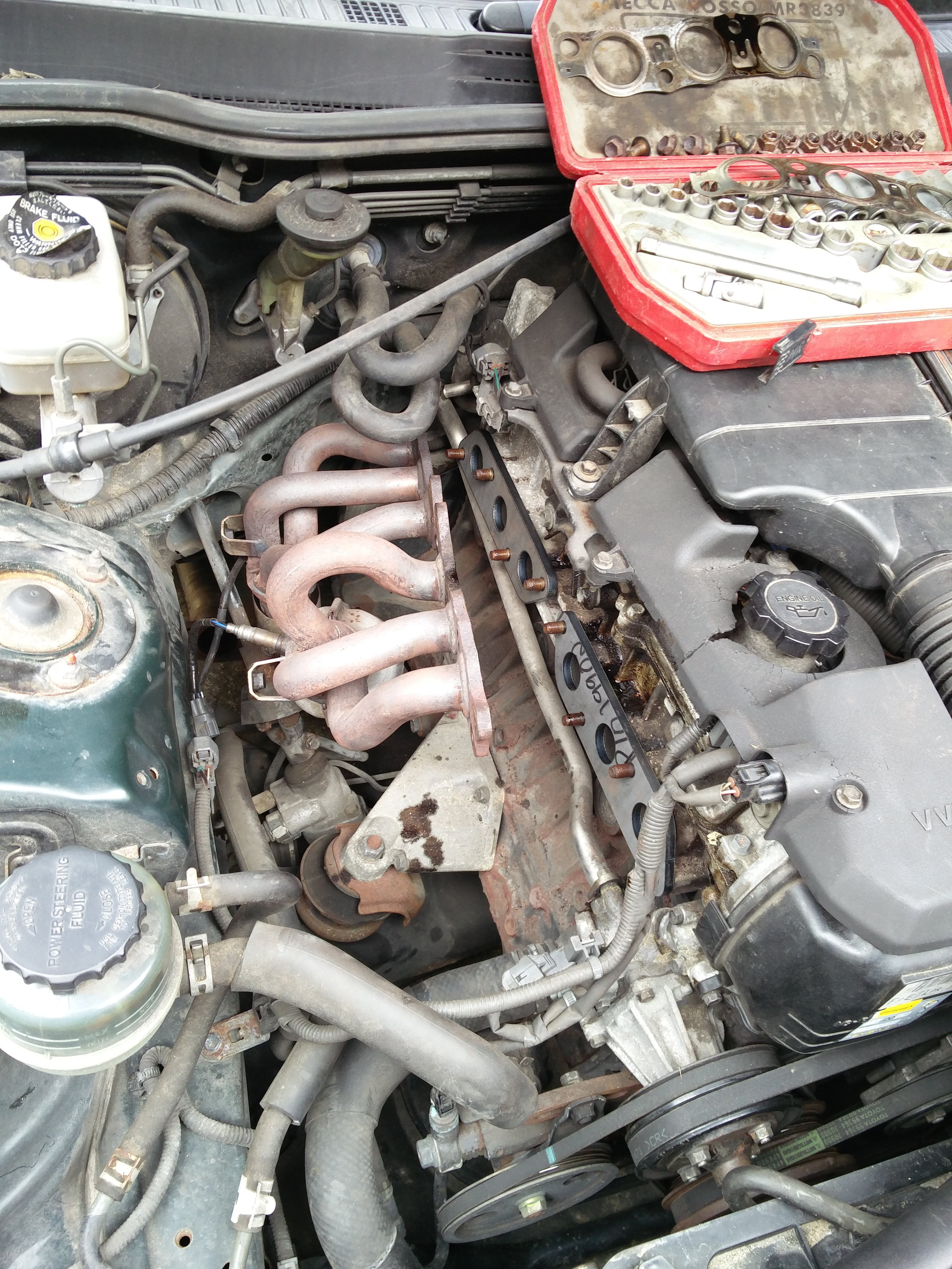
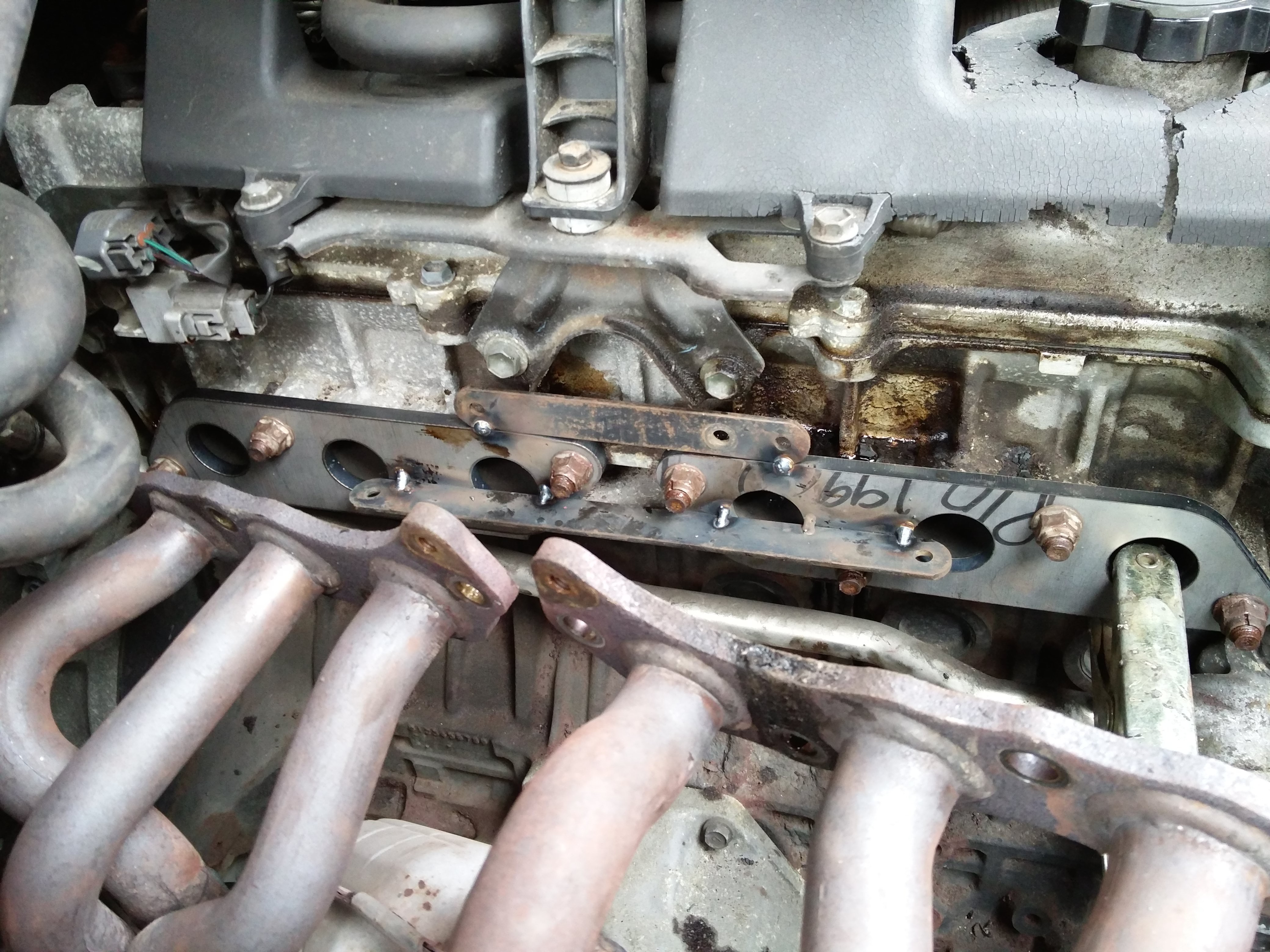
I have finished the exhaust manifold. Here it is fitted to the car. Luckily it didn’t move much whilst welding and the flanges fit well. I may need to get them skimmed to seal properly but I won’t really know until I run the car for the first time
I have finished the exhaust manifold. Here it is fitted to the car. Luckily it didn’t move much whilst welding and the flanges fit well. I may need to get them skimmed to seal properly but I won’t really know until I run the car for the first time. ![]()
![]()
I spent some time messing about with the cold side of the system. I originally brought a Mercedes sprinter intercooler. These are very cheap and have 63mm tube connections. I couldn’t really find any dimensions at the time so just ordered one brand new for £38 delivered. As you can see it was far too big. It could have been squeezed In I suppose but I would have had to cut up the front bumper allot, run the car without the front crash protection bar and the plumbing would have been messy as the tubing would have had to come forward before heading back into the engine bay, as the photo.
![]()
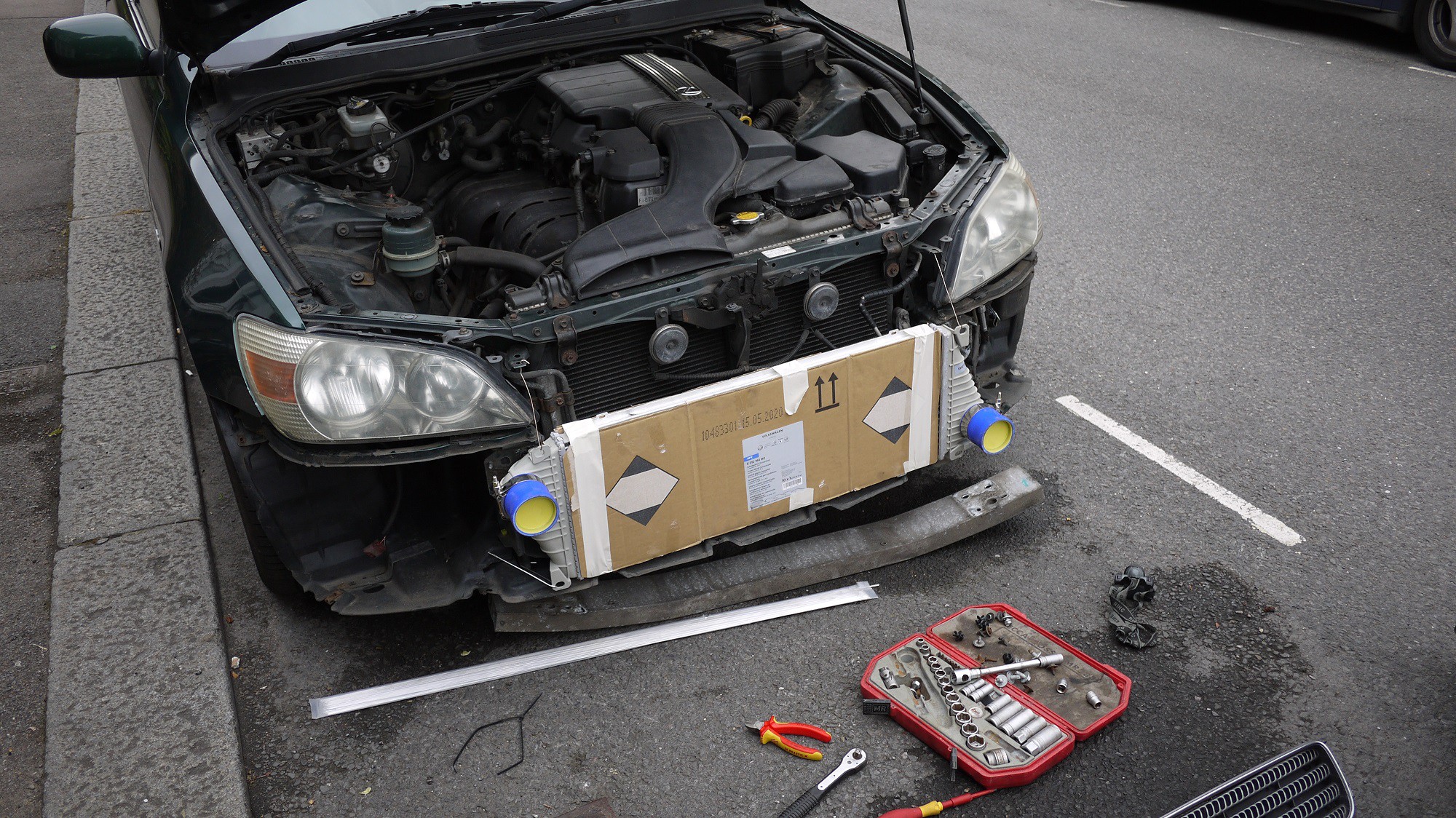
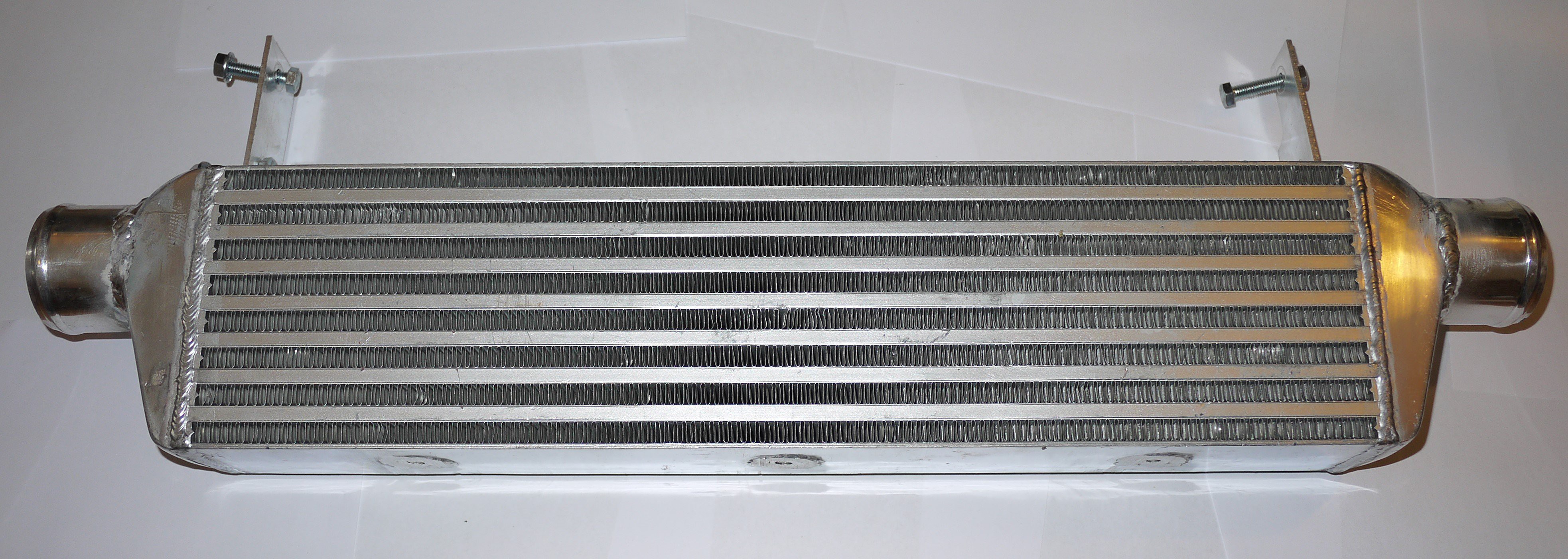
After this I had a good measure up and found a bargain on ebay. I now have an intercooler with dimensions 550x140x65. This fits very nicely. It was cheap because it came pre-damaged. It still holds air though. I added some brackets and it now mounts to the crash protection bar that fits inside the front bumper. I also welded on some 63mm tube connections to match my pipework. This was the first time I have welded anything important in aluminium (after about 2 hours practice) it’s not impossible but my efforts here are very messy. I wont give you any close up photos! It is still air tight though.
![]()
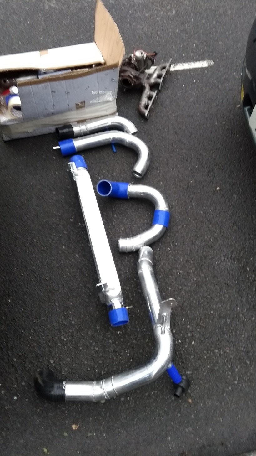
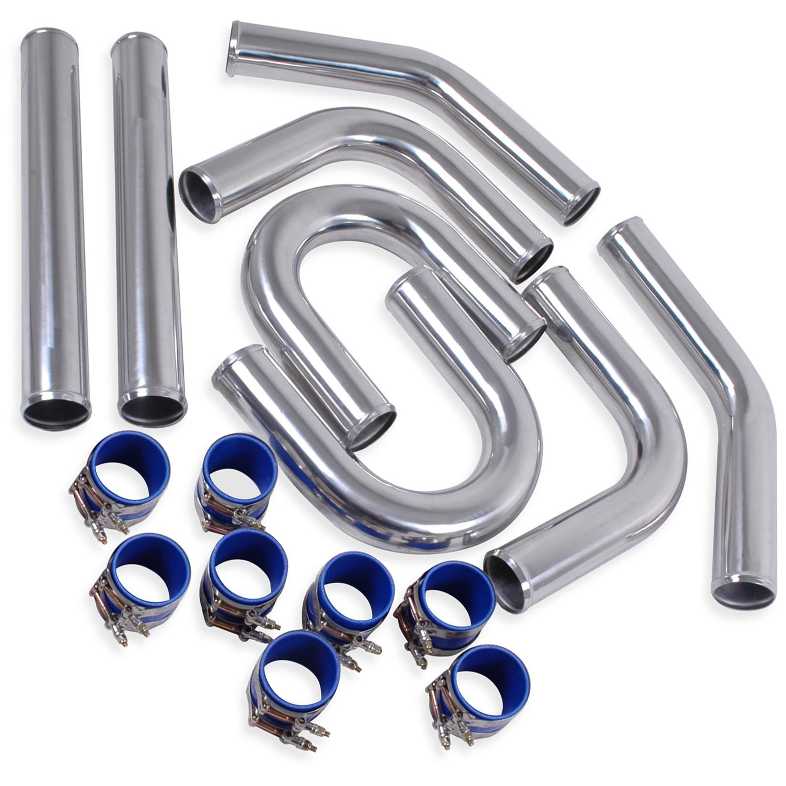
I ordered an ebay special intercooler tubing kit. I was quite impressed with this. You get everything you see in this picture for £80 delivered. I had to buy a couple of silicone elbows purely because the radius of the bends in the kit are quite large, about 100mm.
I have ordered a custom braded line for the turbo oil feed. I have the bits for the turbo water flow and return as well. For this I am using standard M12x1.5 banjo to hose barb fittings. The flow and return will tee into the throttle body heater lines.
I ordered an ebay special intercooler tubing kit. I was quite impressed with this. You get everything you see in this picture for £80 delivered. I had to buy a couple of silicone elbows purely because the radius of the bends in the kit are quite large, about 100mm. ![]()
![]()
I have mocked up all of the tubing with aluminium tape ready for welding. I had planned to do the welding in a couple of hours last weekend but that was a bit ambitious. I need much more practice before I attempt this. The tube has a 1.5mm wall and is very unforgiving for bad welding technique. I was using 2.4mm tungsten’s and filler. A bit of research suggests the use of 1.6mm filler and perhaps a 1.6mm tungsten. I think my shielding gas flow was much too high as well causing turbulence. Luckily I did not need the two straight sections in the kit so this give me plenty of material to practice with.
I have ordered a custom braded line for the turbo oil feed. I have the bits for the turbo water flow and return as well. For this I am using standard M12x1.5 banjo to hose barb fittings. The flow and return will tee into the throttle body heater lines.The turbo oil drain needs to feed straight back to the sump for which I need to attach a hose fitting. My sump is pressed steel so I can’t drill and tap a fitting into it. I could have welded something on but I didn’t want to risk warping it and cause oil leaks from the sealing surfaces. A bit if ebaying got me the following: A ‘15mm compression tank connector’ will seal into the sump. 15mm copper compression fittings have a ½’’ BSP male thread so I can use a female threaded elbow to join this to a 19mm hose barb. This was a mm or so too large but it’s all that I could find.
![]()
So the mechanical side is nearly finished. I need to spend some time on the electronics. My original plan was to use a micro controller to hold the fuel injectors open after they had been fired by the ECU for a period calculated by the boost pressure and the engine RPM. This is complicated and timing critical so I have been trying to come up with something more simple. I’m thinking along the lines of an electronically controlled fuel pressure regulator. It will have its own project page as I can’t find anyone that has done this.
-
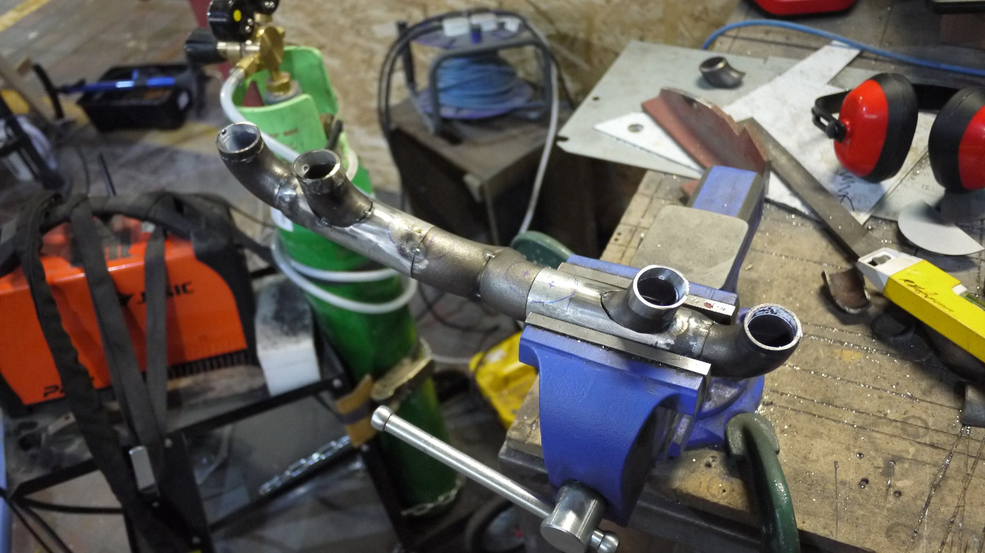
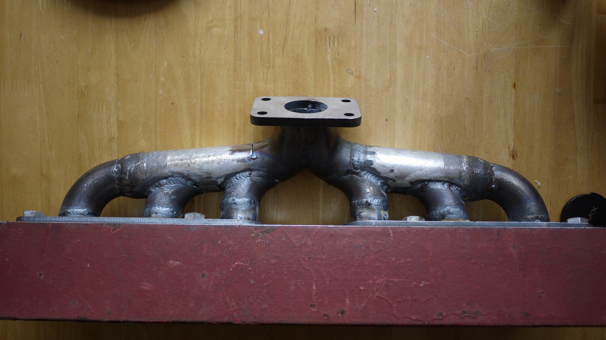
Progressing on the turbo exhaust manifold
04/23/2017 at 15:31 • 0 commentsI went down to building bloqs in north London the other day buildingbloqs.com to build the 6 into 1 exhaust manifold. I cracked on hard for about 11 hours but didn’t manage to finish it one day as I had hoped. It’s all tacked together though and about 30% finish welded. I'm quite happy with how it went. There are some gaps up to about 1mm wide which can be filled with weld but will increase the chances of the whole thing warping. I spent about £30 on the tube and bends from DC iron www.dciron.co.uk. Super cheap which is goal on this project. I treated myself to an air die grinder (£20 from screwfix, part number 5458H) and a decent carbide burr (a tenner from ebay). That definitely saved me a few hours. Cuts through steel like butter. Dont forget you can click to enlarge photos.
![]()
![]()
![]()
![]()
-
Starting the turbo exhaust manifold
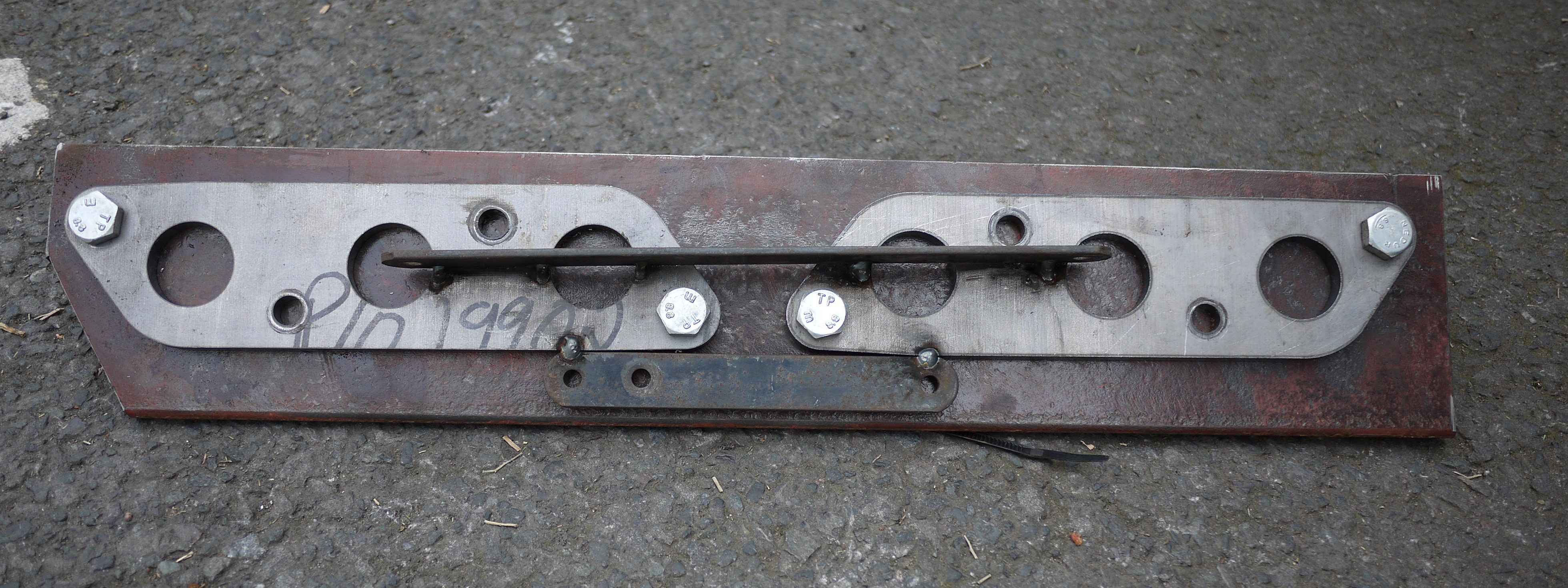
04/17/2017 at 10:39 • 0 commentsI removed the stock headers and checked the fitment of my laser cut flanges. Luckily the fit is spot on.
![]()
To keep the flanges flat while I am building the manifold (welding heat would distort them) I need to bolt them to some thick steel plate. To save complicated measuring to make sure they are in the right place relative to each other I tacked on some steel bar while they were bolted to the engine.
![]()
And here they are bolted to some 13mm thick L section:
I can now remove the temporary bar and add the remaining bolt holes.![]()
-
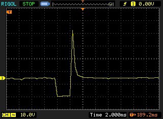
More Fuel Injector Measurements
04/17/2017 at 10:25 • 0 commentsMy girlfriend took me for a spirited drive to test the maximum duty cycle of the injectors. Full throttle at 6k RPM results in a duty cycle of 62%
![]()
This leaves me 38% available which probably isn't enough to feed the engine on full boost but will get me started. I can always install a rising rate fuel pressure regulator to get a bit more flow.
-
ECU Adapter & Fuel Injector Measurements
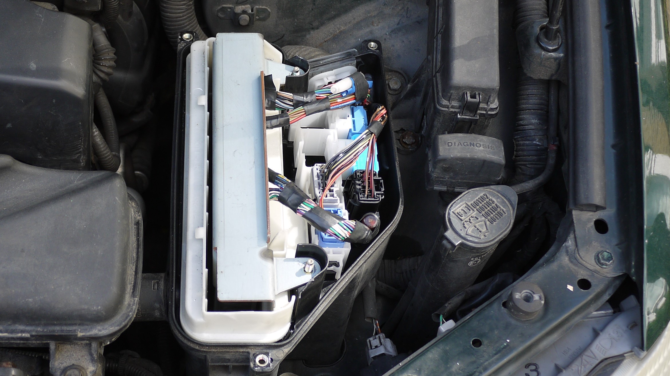
04/15/2017 at 16:06 • 0 commentsI really needed to investigate how the ECU controlled the injectors before I went much further on the design of the piggy back ECU. I was worried that the ECU might PWM the injectors during each injection stroke rather than fire a single shot.
Due to the way that the ECU is installed in the car, it was not possible to probe any of the ECU pins without cutting the loom. Note the ECU mounting bracket that covers the connectors.
![]()
I should note that you cannot even unplug the ECU without removing this mounting bracket. To do this you must remove 4 tamper proof bolts. These look like a tamper proof tox head but the central pin is a bit larger. very annoying. A bit of research shows that they may be a tamper proof 'torx plus' head. I just drilled them out and replaced them with some normal M5 bolts...
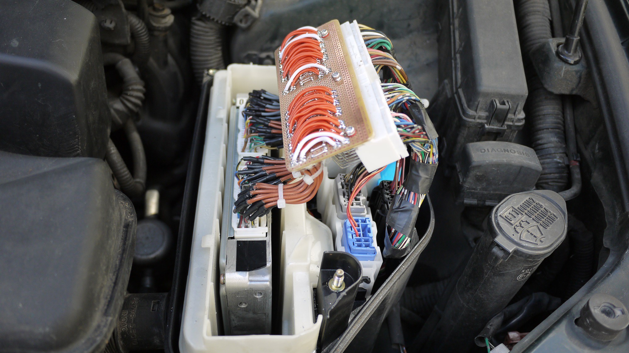
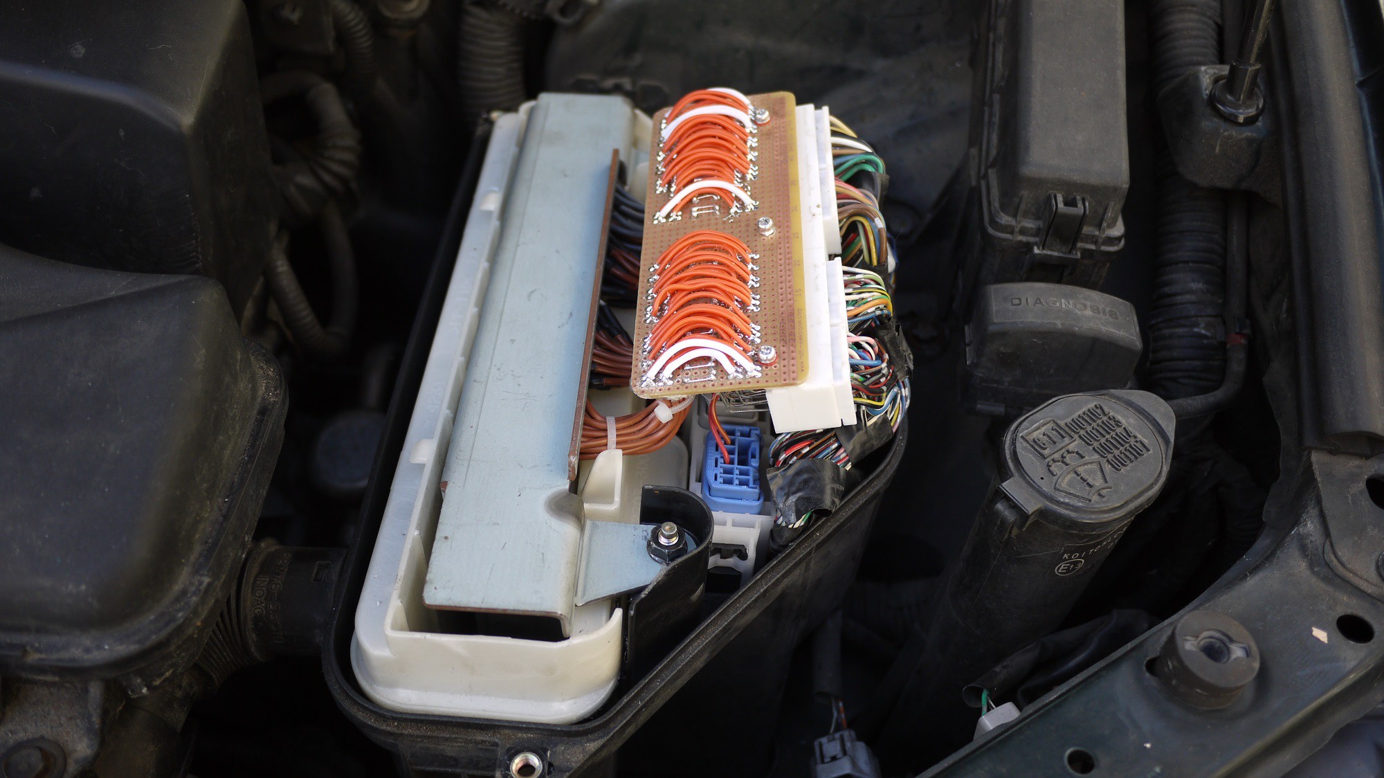
I was able to unsolder the connector from my spare ECU (not easy using a soldering iron and a cheap solder pump, took about 3 hours) and make an adapter board. This will allow me to probe signals while the engine is running. It will also give me a neat way to tap off and interrupt signals to my piggy back ECU. Here it is installed below. This just fits under the electronics box cover.
![]()
The ECU mounting bracket hides the joints and makes it look much neater!
![]()
Although I had fully tested the adapter board I was still a bit nervous turning the key. Luckily the engine started fine and there was no magic smoke released.
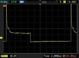
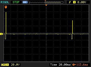
With the engine running I was able to identify a few signals of interest. Most importantly the drive to the fuel injectors. Here is injector 1 at idle (about 700 RPM):
![]()
![]()
The ECU grounds the injector as I had expected. Also it seems to only fire a single pulse on each cycle. I need to put the engine under full load to check this however. I'll get my girlfriend to take me and the oscilloscope for a drive over the next few days.
It will be interesting to see what the injector duty is at full load in NA form. This will indicate how much head room I have to extend the injector duration before 100% duty cycle is reached. I may have to increase the fuel pressure to get correct fuelling at full power with the turbo.
-
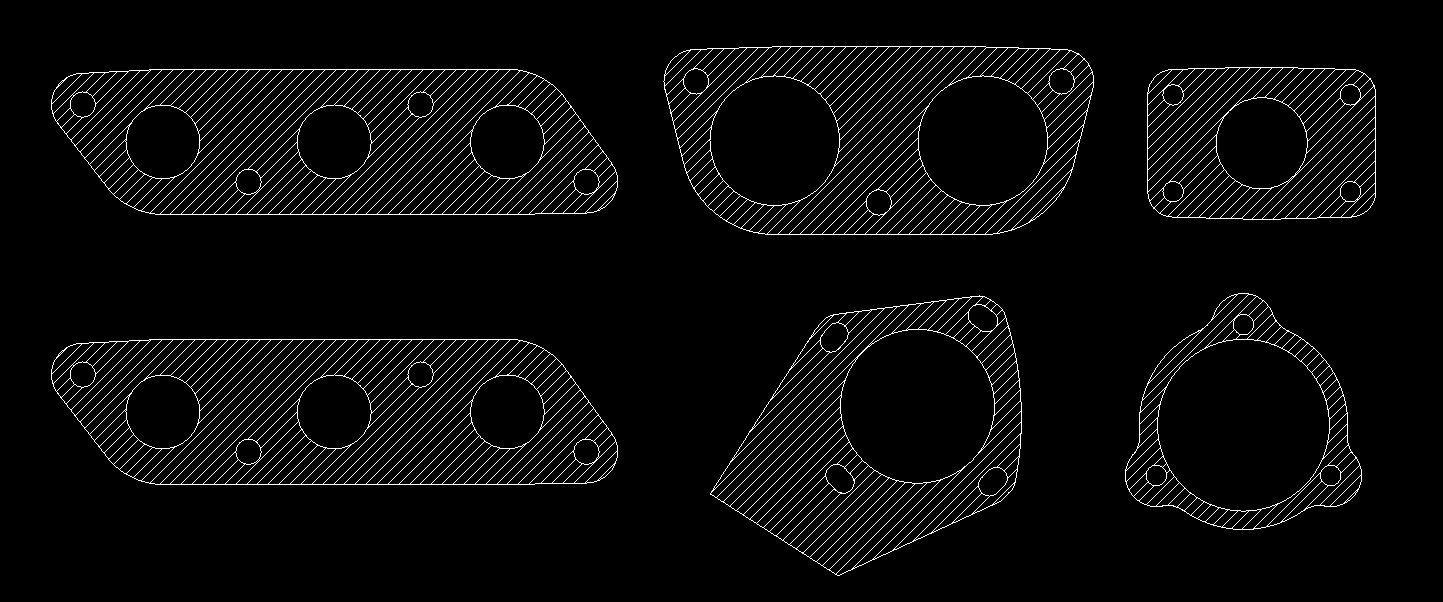
Laser Cut Parts Ordered
04/05/2017 at 10:32 • 0 commentsI have ordered the laser cut flanges for the project. All parts are 8mm steel with the exception of the inlet throttle body flange which is manufactured from 10mm aluminium. I ordered the parts from GAP Metal Ltd in Hailsham, East Sussex (UK). Total cost came to £84.83 including VAT and delivery. CAD files for the parts are uploaded on the project page.
![]()
-
ECU Software
03/22/2017 at 22:25 • 0 commentsI have been working on the code for the piggy back ECU over the last few days. I am currently using an ardunio micro to simulate the factory ECU by creating 6 injector pulses at variable pulse lengths (engine load) and frequency (engine RPM).
The injector pulses are read by an arduino mega 2560. The engine RPM is calculated and manifold pressure is read. These two variables are used to read from an 18 x 16 array (the fuel map) this then used to extend the open time of the injectors after they have been closed by the factory ECU.
At the moment it all seems to be working quite well untill the injectors reach a 100% duty cycle.
![]()
-
Found a Workshop!
03/17/2017 at 13:06 • 0 commentsFor this project I want to make a nice aluminium intake plenum and associated pipework to/from the intercooler. For this I will need an AC tig welder. My tig welder is DC only, bit of an oversight when I brought it.
I looked into 'community workshops' in London. There seem to be a few starting up. I went for a tour of Building Bloqs in north east London yesterday in north London near Tottenham. Very impressed with their facilities and staff. I would strongly recommend anyone in the area to go and check them out. They have facilities to a very high standard and I think their prices are reasonable.
Turbo Lexus IS200 (on the cheap!)
Improving the performance of an IS200. Goal - Under £1000