 Bud Bennett
I covered this topic before for the old differential probe design. I need to revisit this topic because I got it wrong and need to correct it. The other log posting is here. I will be brief.
I was reviewing a few articles on scope probe ground lead inductance when I noticed that many of them called out a 200nH inductance, which seemed too small to me, based upon my previous effort. I decided to check a couple of web-based self-inductance calculators and found that there is an order of magnitude difference between some of them.
The calculator that I used previously, is this one. It calculates the inductance of a 100mm length of 1mm diameter wire is more than 1.5uH. If you consult this other calculator you get 105nH. WTF!
The only way to determine which is correct is to measure it yourself. I took a 250mm length of 26 AWG solid wire, formed it into a loop with a diameter of 8cm and soldered it across a 100nF±1nF mylar capacitor.
Calculator number 2 also has a loop inductance calculator that predicts this piece of wire should be 224nH (308nH if straight). I calculated that the LC tank should therefore have a peak at 1.06MHz. It peaked at 1.02MHz...close enough to verify that calculator number 2 has the proper mojo.
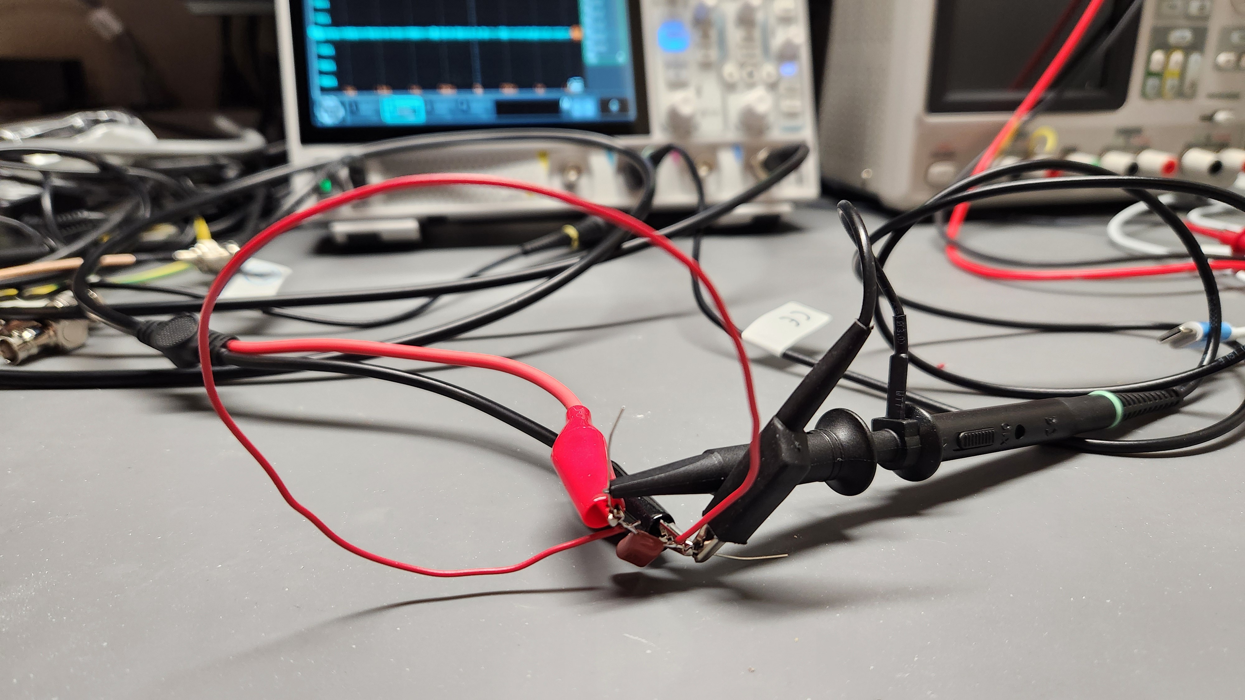
I ran a simple simulation to pick the proper value for the series resistor to de-Q the lead inductance, if using 100mm long leads. It is somewhere between 200-250 Ohms. I picked 220 because that was the closest I had for a 1/8W leaded resistor.
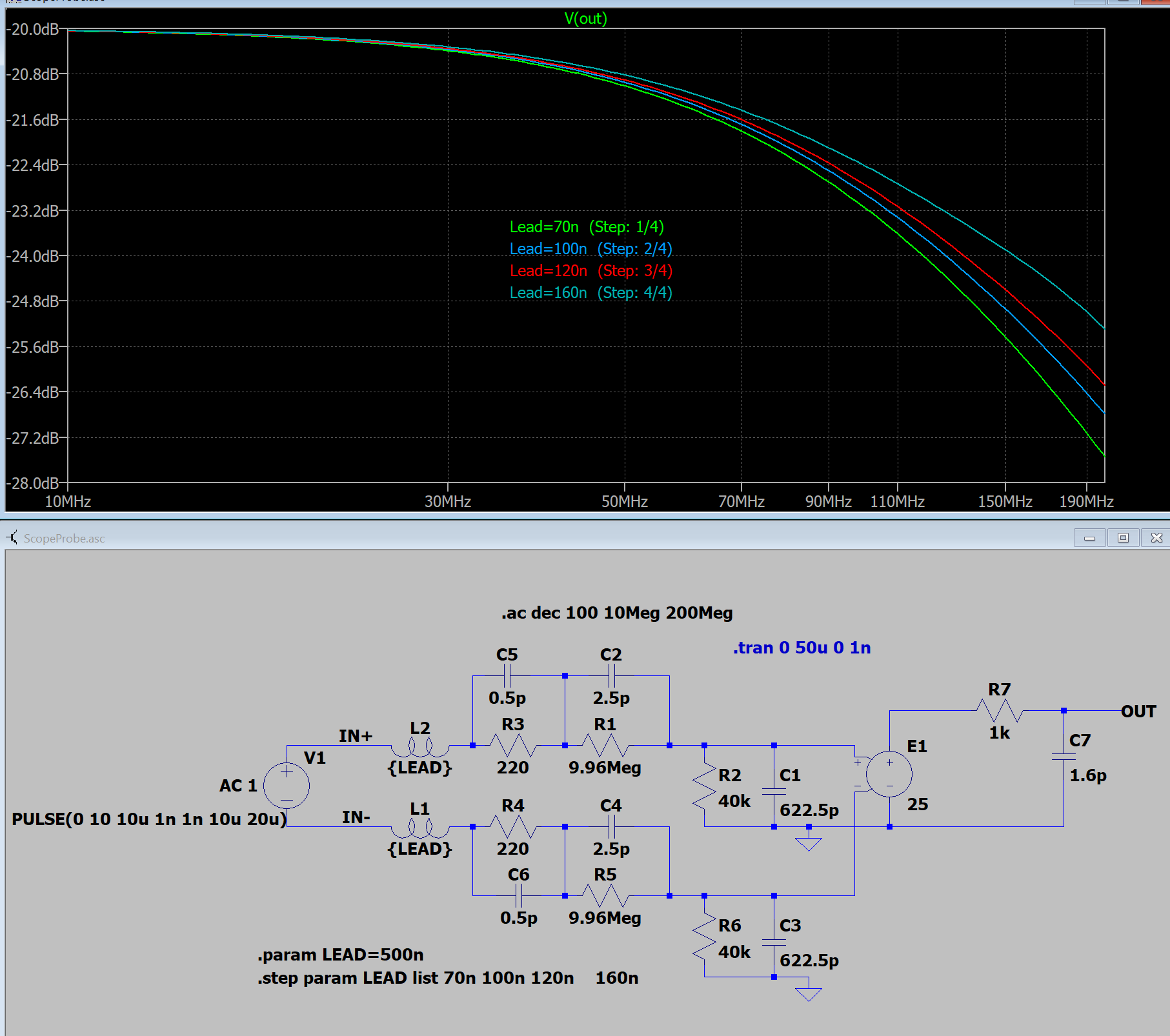
For 70nH - 160nH the output varies 0.8dB @ 100MHz. Good enough. I built as set of these leads and and I can't see any difference (to 60MHz) between the short pins and the longer leads.
Q.E.D.
Discussions
Become a Hackaday.io Member
Create an account to leave a comment. Already have an account? Log In.