 Bud Bennett
Don't make the mistake that I did.
I ran out of 220pF NP0 capacitors for the input attenuator, so I substituted with a strip of unspecified 220pF caps that had been in my inventory since I started this hobby some years ago. I think that I got them from Banggood or AliExpress -- very inexpensive -- probably claimed they were X7R or X5R grade. It was a big mistake.
When I tried to compensate the probe there was a short spike at the leading edge of the square wave output that would not disappear by adjusting the trim capacitor. The other odd thing that I noticed was that the spike was constant amplitude and did not change when I was varying the trim capacitor. It looked like this on the scope:
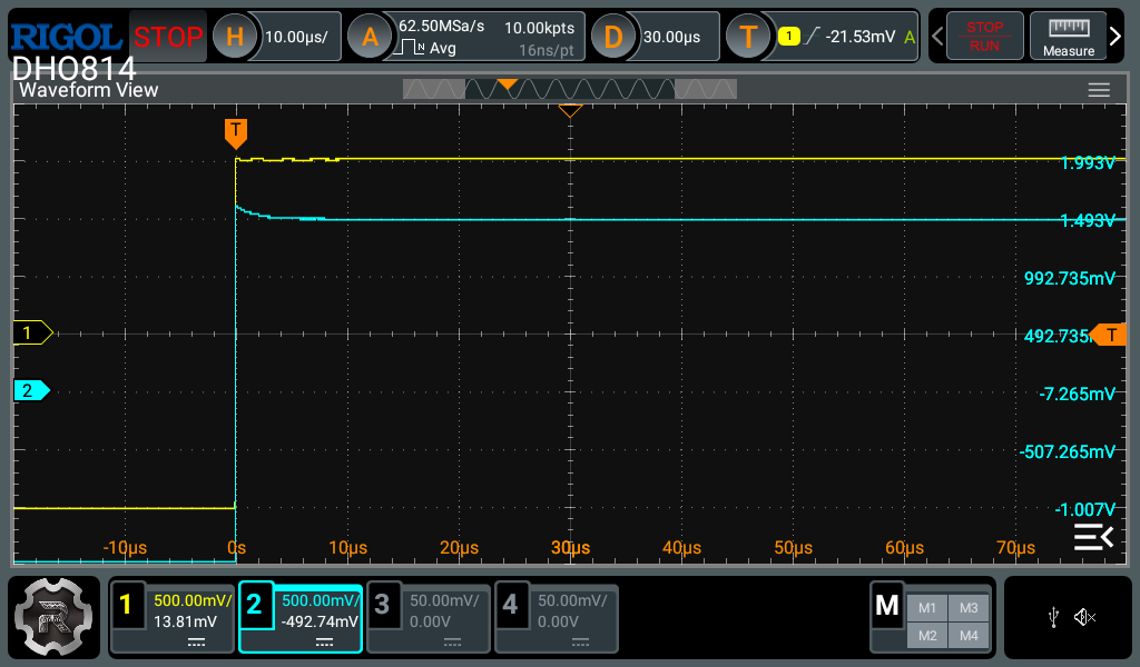
CH1 is the probe input. CH2 is the probe output. Note how short the duration of the spike is -- around 1µs time constant. The probe appears to be nicely compensated otherwise because it is pretty flat after a few microseconds. (The time constant of the attenuator is much longer than 1µs.)
So what caused this? The constant spike size indicates that it is some resistance in the attenuator. Most probably a capacitor with significantly higher ESR (Equivalent Series Resistance.)
When I was looking at capacitor datasheets I found this gem from Kyosera:
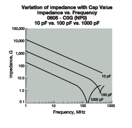
I had always assumed that ceramic caps had very low ESR. Not true for the lower values. And Kyosera offered even more insight:
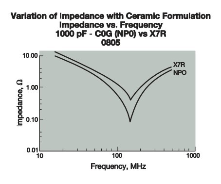
That's a 5x poorer ESR for an X7R ceramic. I set up a simulation to see what LTSpice thought about it. All of the capacitors in the attenuator now have higher ESR to match the datasheets -- somewhere between 100mΩ and 500mΩ. With fast rise/fall edges on the applied input square wave the output shows the spike on a perfectly compensated probe.
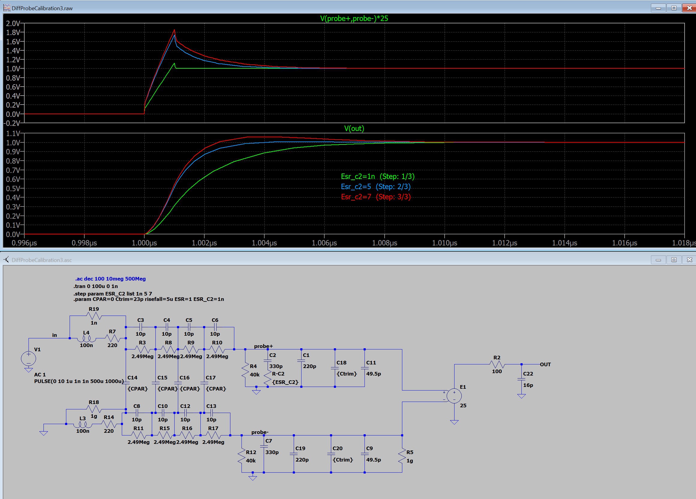
I put the extra ESR in series with C2. The spike gets softened by the bandwidth of the probe, but is noticeable as a 3-5% peak. SPICE also indicates that the spike will almost always be present when using extremely fast rise/fall edges.
The takeaway from all of this is to use very good quality capacitors in the attenuator (and probably everywhere else) and slow the down the edges of the waveform used for compensation. That's why I suggest using a square wave with 100-300ns rise times because the spike won't appear and distort your measurements.
No Spike from the 10MHz or 1MHz Probe:
The effect of the capacitor ESR is evident for frequencies above 10MHz. The lower frequency probes probably won't show this effect no matter how poor the capacitors are.
Discussions
Become a Hackaday.io Member
Create an account to leave a comment. Already have an account? Log In.