 Makestreme
-
1Prepare the AI module
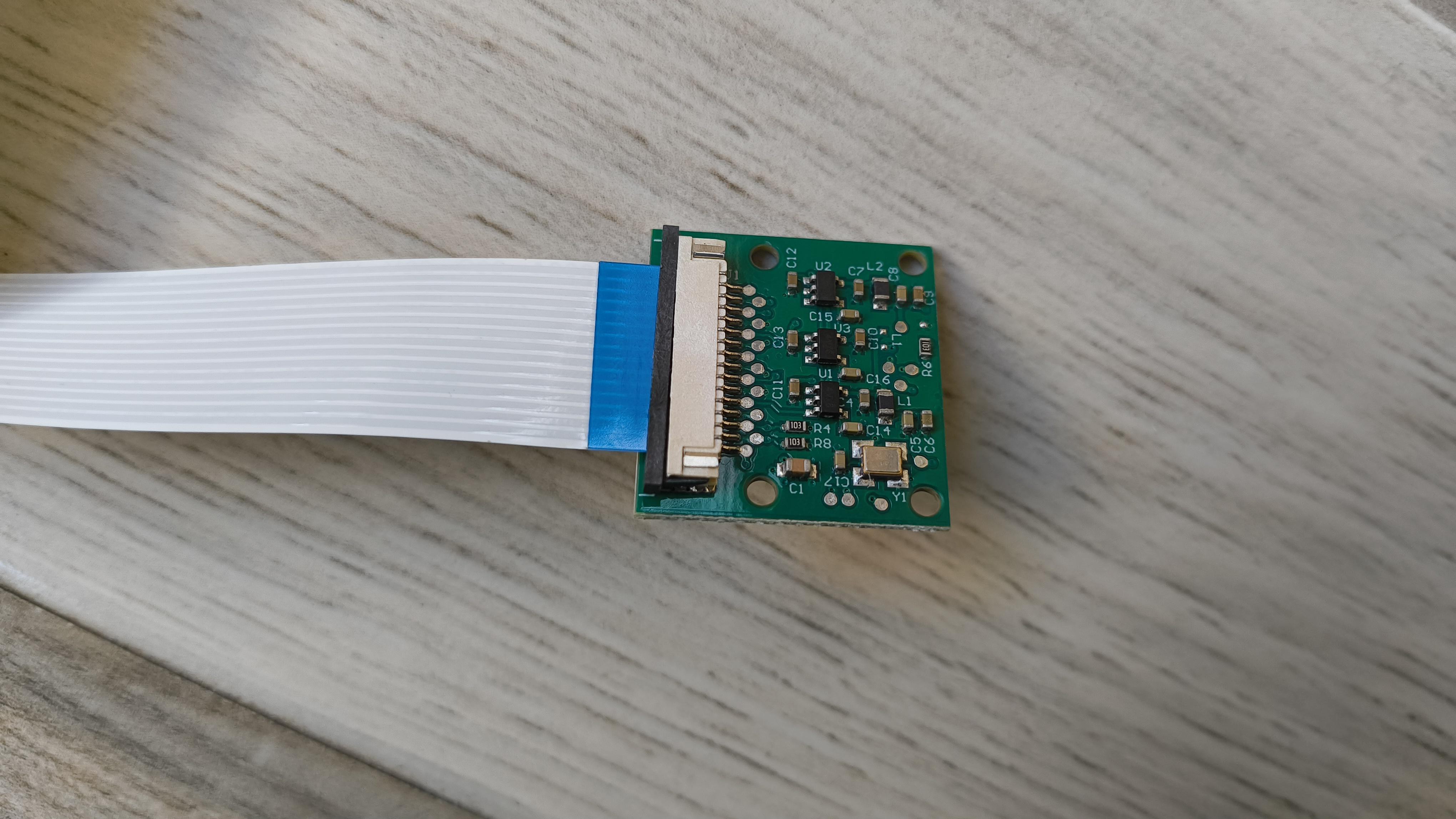
The Grove Vision AI module is a handy little device. It can be trained to detect all sorts of things. Humans, pets, gestures, toilets (yes, really!), and much more. Check out some of the pre-trained models here: Sensecraft AI.
To get started, I connected the cable to the AI module as shown here.
![]()
Next, I plugged the other end of the cable into the Raspberry Pi camera, as shown here.
![]()
Now we’re ready to start uploading the model.
-
2Justway
Part of this project was supported by Justway
![]()
Justway offers a comprehensive suite of solutions, including CNC machining, 3D printing, sheet metal fabrication, injection molding, and urethane casting, offering rapid prototyping and mass production solutions.
Get your project 3D printed by Justway's 3D printing service. Head over to Justway's 3D printing service and select 3D printing.
![]()
Right now, you can also take advantage of Justway's Summer Cashback Event, where you get 15% cashback on all successful orders placed between June 1 and August 31, 2025 (UTC). This offer applies to the actual paid amount and is a great way to save on your manufacturing needs, whether for prototyping or mass production
Don't miss this opportunity to get high-quality manufacturing services while enjoying significant cashback rewards.
-
3Upload the AI model
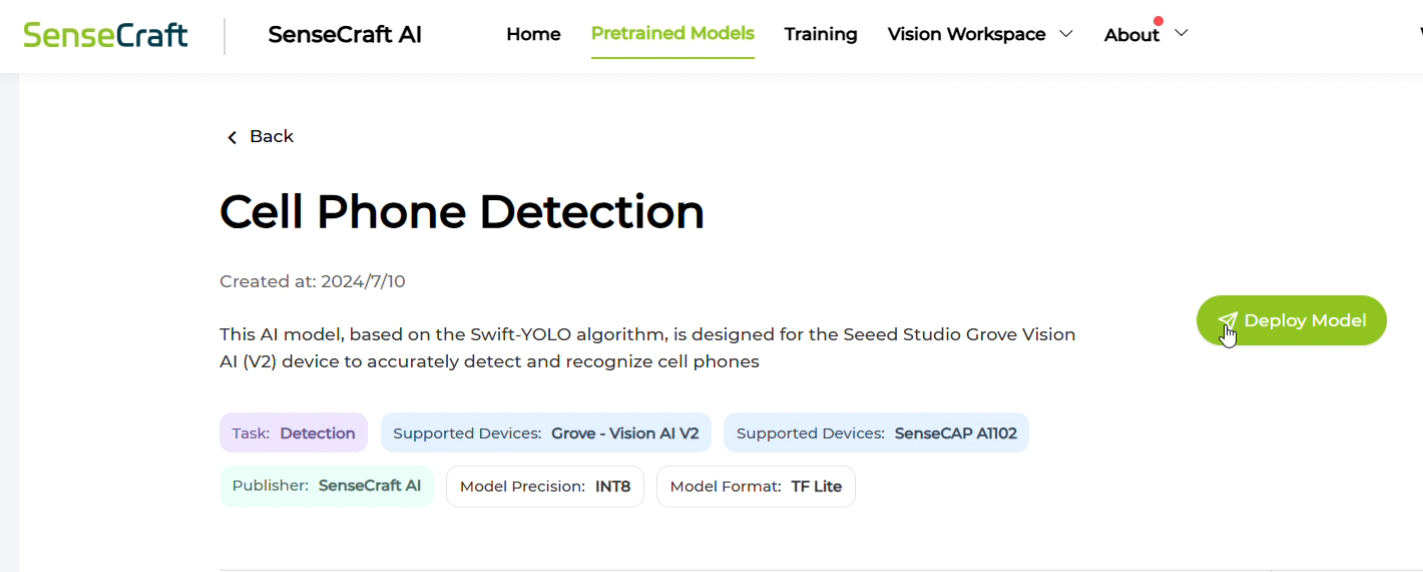
I went to the Sensecraft AI models page and searched for "cell phone detection."
This website contains pre-trained models that can be uploaded to the Grove AI module. If you don’t find the model you’re looking for, you can even train your own by uploading images of specific categories. However, for this use case, I found a suitable model already available on the site.
![]()
![]()
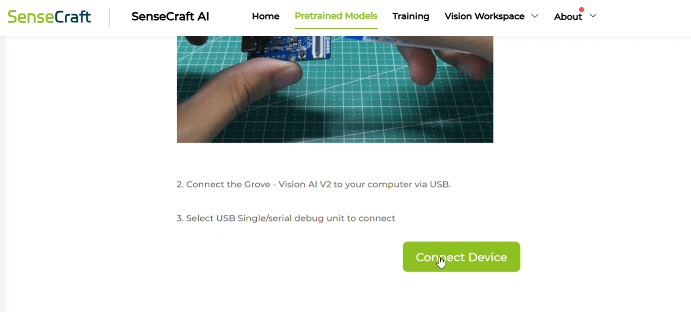
If you’re following along, make sure to use only the models designed for the Grove Vision AI Module v2!
Next, connect the AI module to your PC using a USB-C cable, and click "Connect Device."
![]()
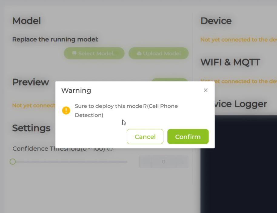
Your browser may prompt you to choose a device—select the correct port (there should only be one) and confirm.
![]()
![]()
-
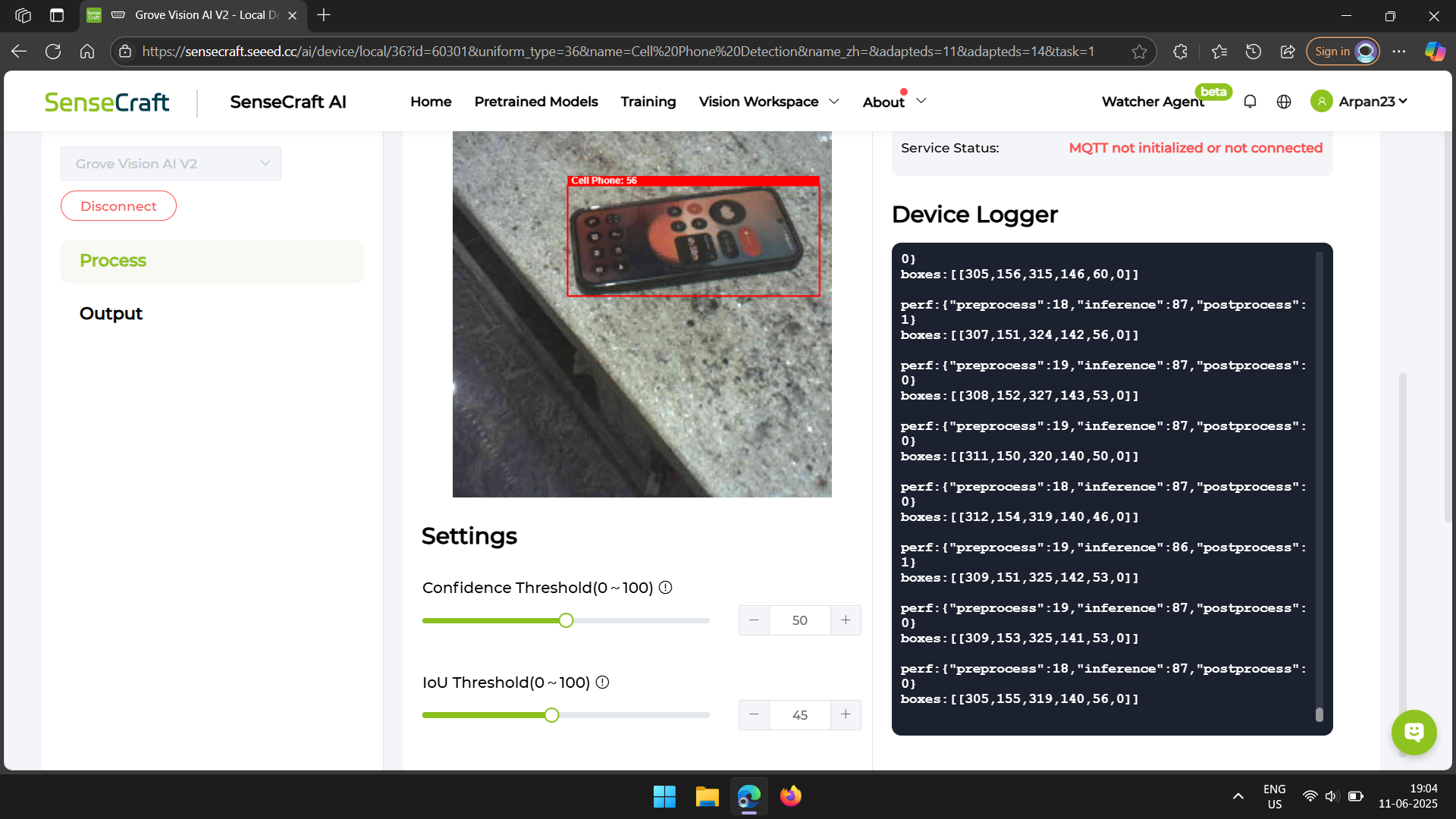
4Test the model
After the model finished uploading, I could see the camera feed on the webpage. Next to it, there’s some text that shows what the AI module is detecting.
I pointed the camera at my desk, where my cell phone was lying. I tried pointing it from different angles, and each time the phone was successfully detected.
![]()
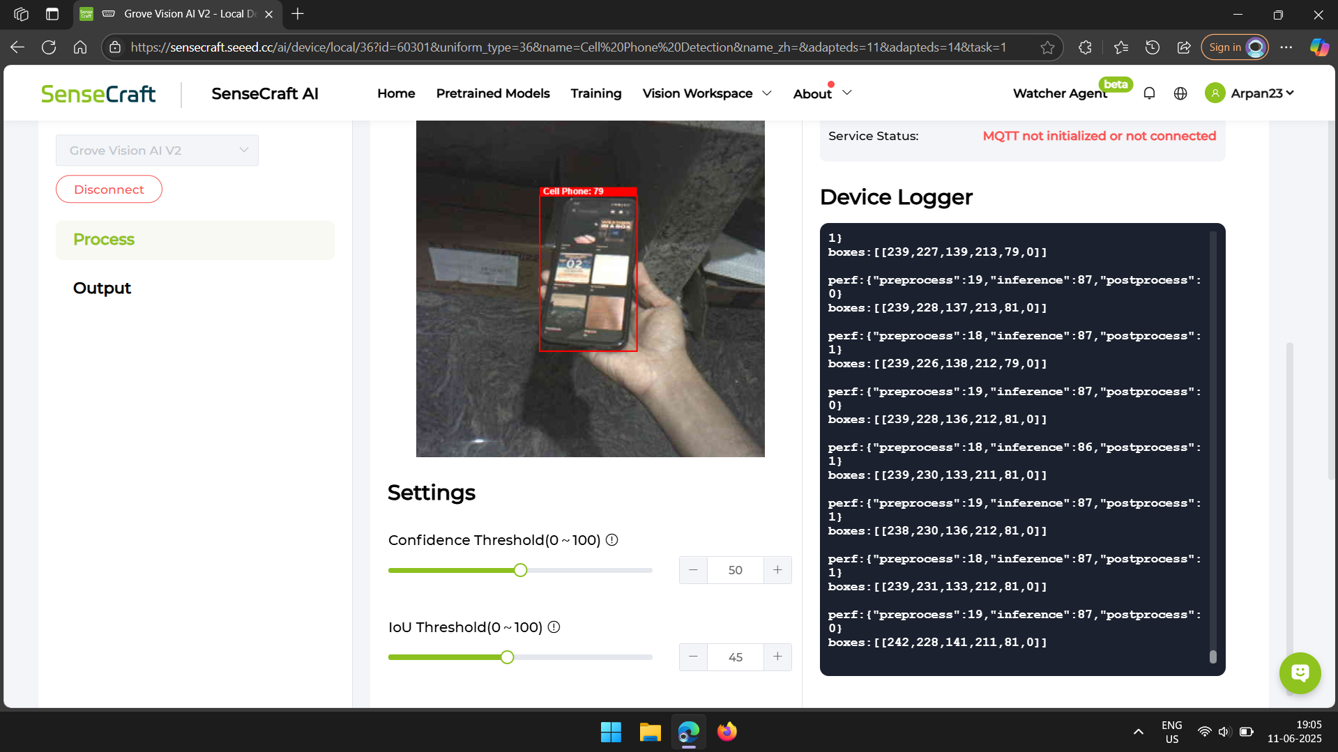
As you can see in the images, the camera feed draws a red box around the phone as soon as it’s detected. Later, we’ll write code to check for the presence of this red box to confirm that the module has detected a phone.
![]()
![]()
The number displayed on top of the red box indicates how confident the model is about its recognition.
-
5Program the Xiao
This code requires the Seed SSCMA library.
![]()
To install the Seeed SSCMA Arduino library, follow these steps:
- Go to the official Seeed GitHub repository for the SSCMA library: Seeed_Arduino_SSCMA and download the latest version as a ZIP file by clicking on Code > Download ZIP.
- Add the Library to Arduino IDE
- Open your Arduino IDE, then go to Sketch > Include Library > Add.ZIP Library... and select the ZIP file you just downloaded.
This code checks if a cell phone is detected and remains visible for at least 10 seconds, it triggers a smooth colour transition on a WS2812 LED strip from warm white to deep red, indicating the detection of a cell phone. If the cell phone is no longer detected, the LEDs transition back to warm white. The system continuously monitors the camera feed and updates the LED colour accordingly. I have done a detailed code walkthrough in the end of this tutorial.
![]()
My code is attached below.
-
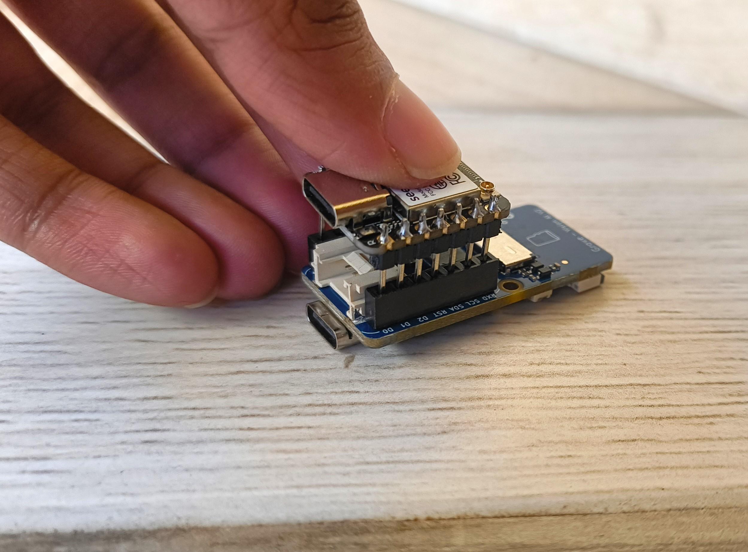
6Solder a wire for the LED strip
I Pushed the Xiao into the female headers in the AI module, Making sure the USB-C port in the Xiao is facing the same direction as the one on the AI module.
![]()
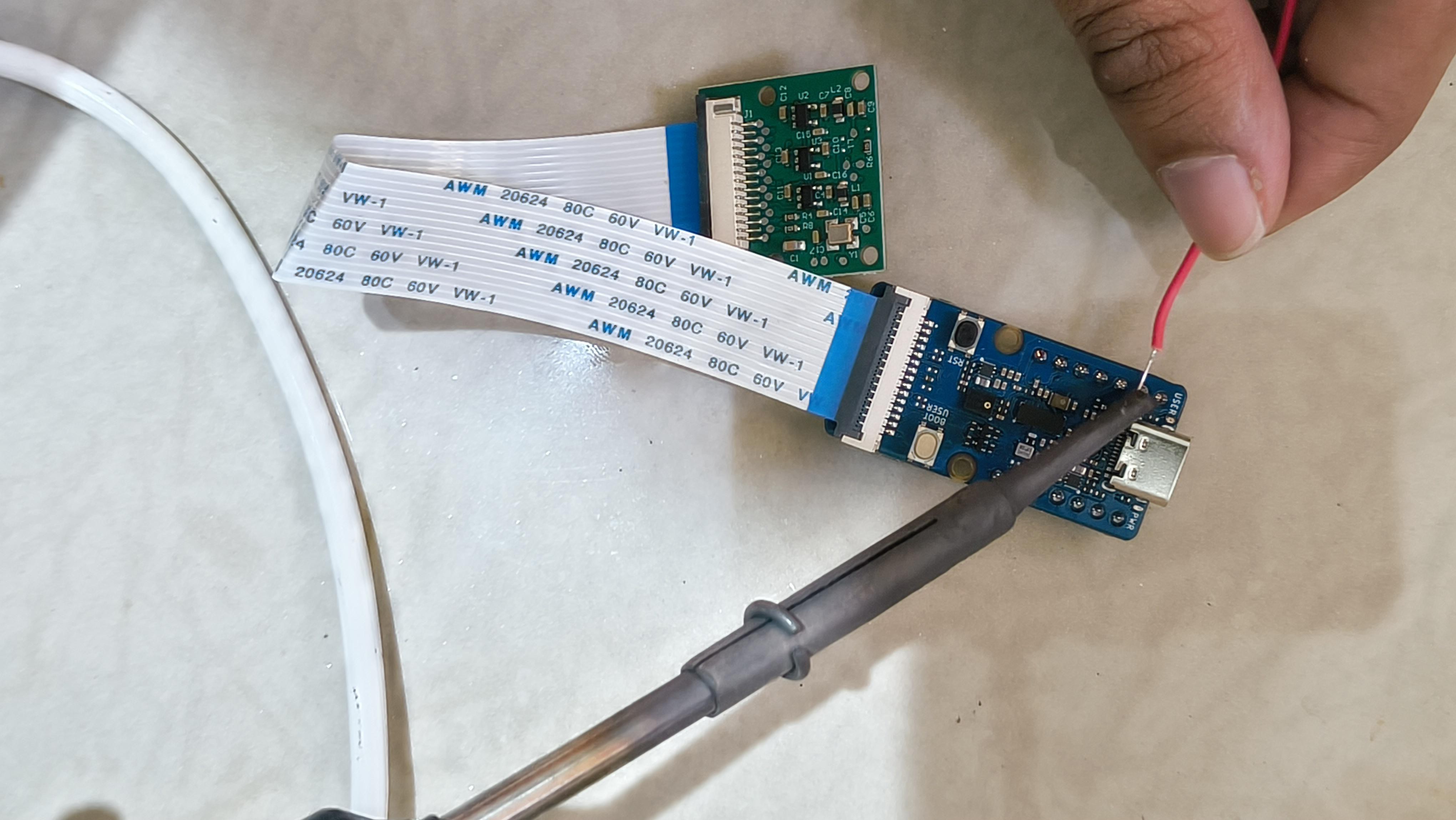
Then I soldered one wire from D2 of the Xiao. I did it on the AI module itself, as it was easier. This will be the data pin to the LED strip.
![]()
In case you're using a different microcontroller like an arduino, you can instead wire it up to the grove module.
Connect the Grove Vision AI V2 module to the Arduino board's default I2C interface using the provided 4-pin Grove cable as follows:
- Connect SCL on the Vision AI module to SCL on the Arduino.
- Connect SDA on the Vision AI module to SDA on the Arduino.
- Connect VCC on the Vision AI module to the Arduino's 3.3V power pin.
- Connect GND on the Vision AI module to the Arduino's GND pin.
-
7Making the Lamp
You can find plenty of 3D models on Thingiverse if you want to 3D print the lamp. However, I built mine using some materials I had lying around the house.
For the neck, I used white tubing and inserted an aluminum wire inside to make it adjustable. For the base, I used a plastic lid, made a hole in it, inserted the tubing, and glued it in place.
![]()
I later added some weight to the base to make it more stable.
![]()
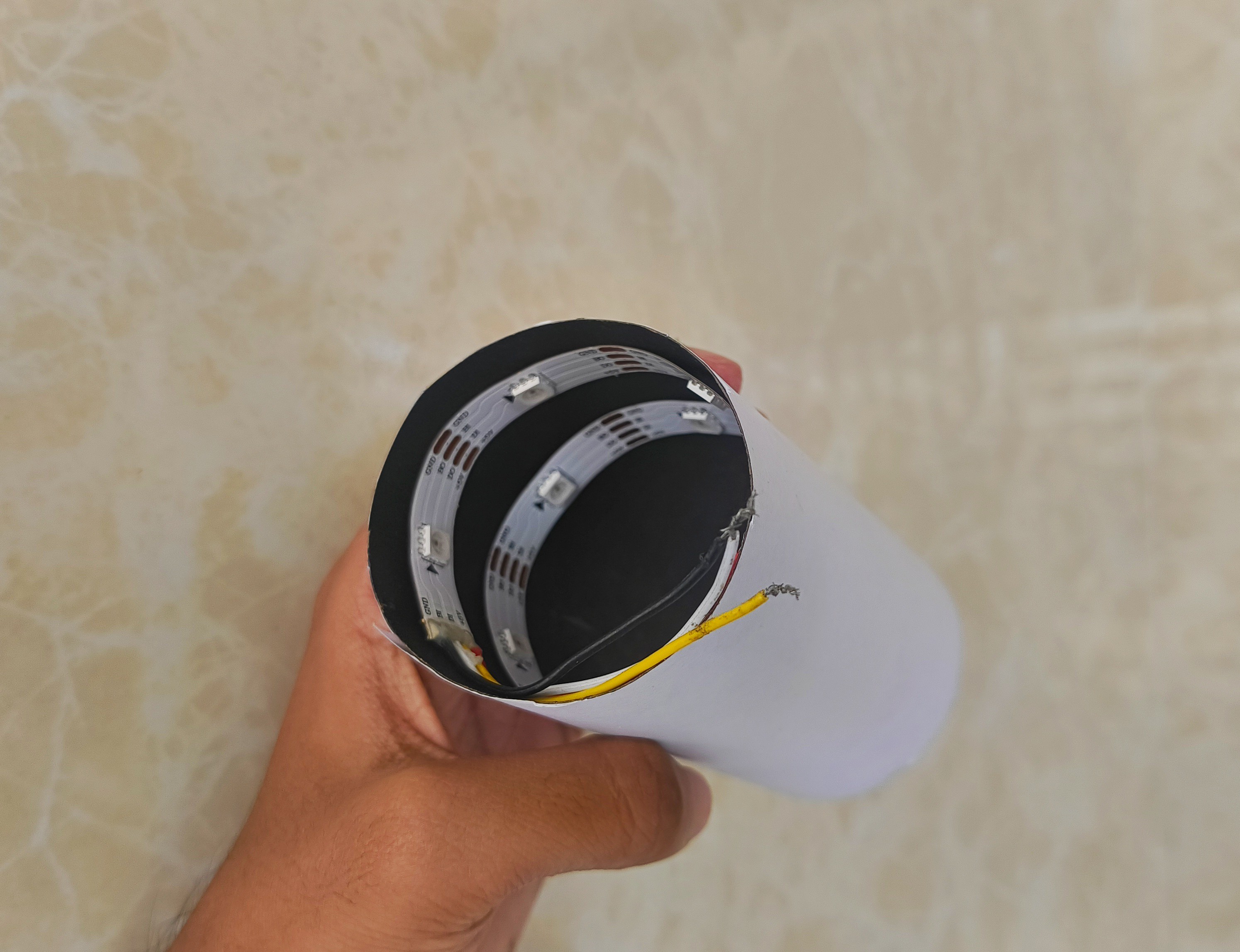
For the head of the lamp, I glued some matte sticker paper onto a tissue paper roll.
Then, I used a strip of 10 WS2812 LEDs, which can be color-adjusted. I glued the LED strip inside the lamp head.
![]()
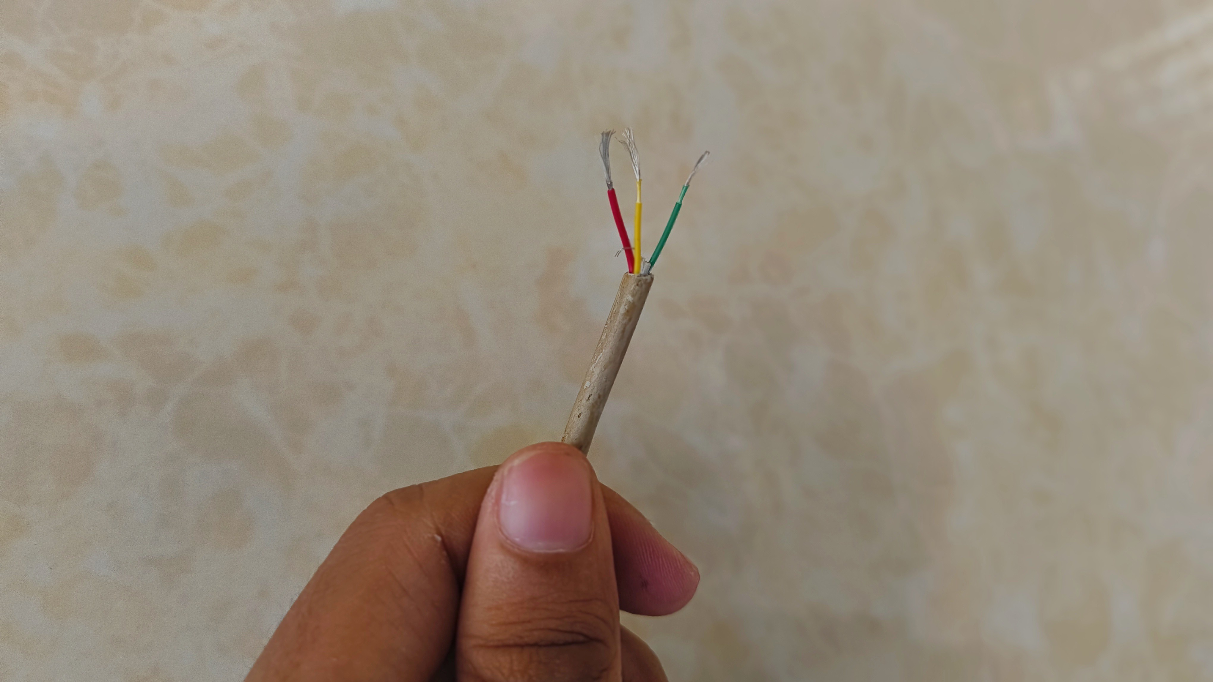
To connect it to the AI module, I repurposed a white USB cable and chopped the ends off. It contains four wires, which is perfect for wiring up the WS2812 LEDs.
![]()
Finally, I glued the neck to the lamp head and routed the wire through the back of the head.
![]()
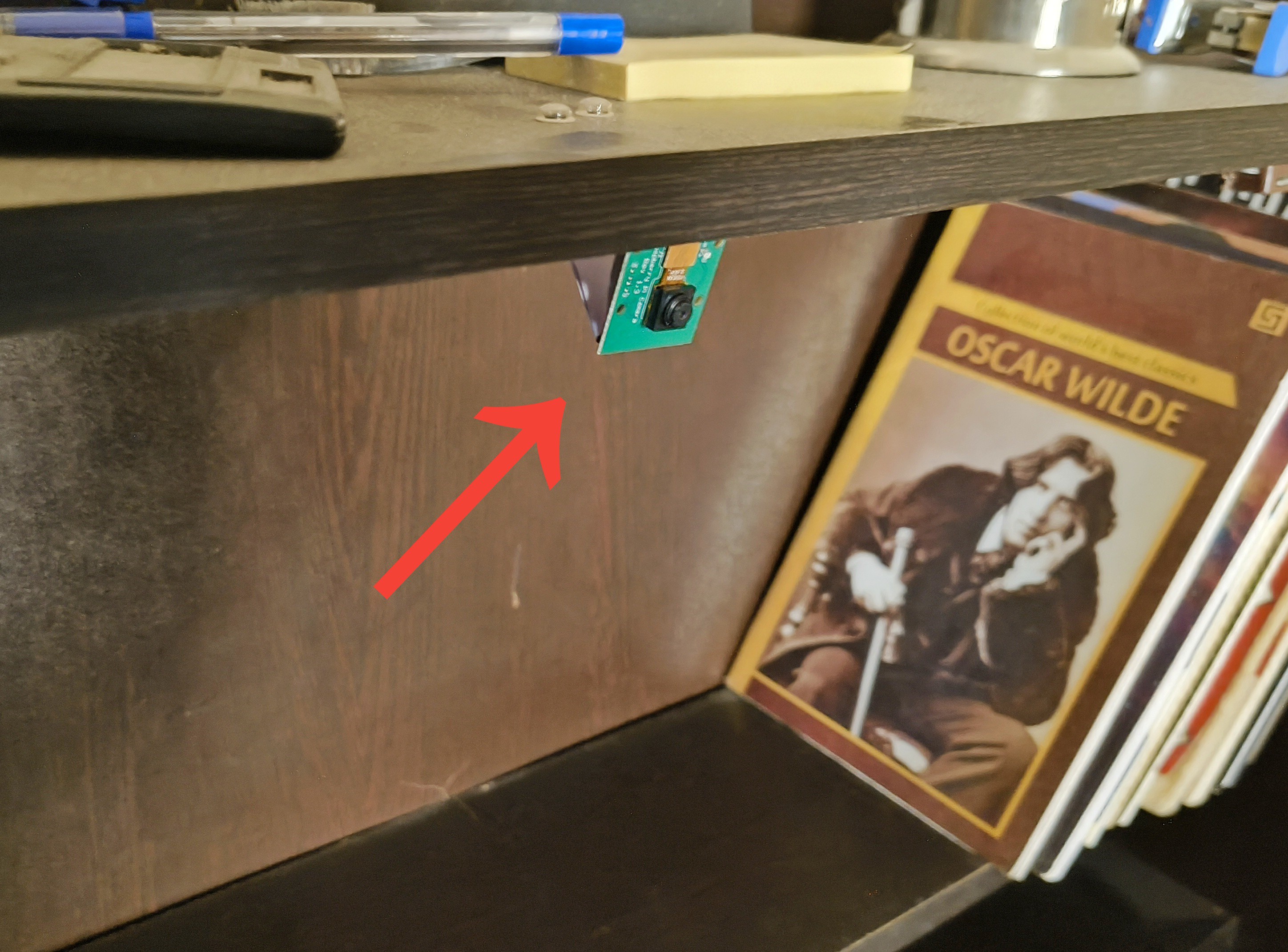
While a 3D-printed lamp could be designed to house the AI module inside, this is just a prototype. So I chose to keep the AI camera system external to keep the build simpler.
![]()
I mounted the AI module on a shelf above the study table, positioning it, so the camera looks directly down at the tabletop. Then, I connected the wire from the lamp to the AI module.
-
8Code Walkthrough
This code checks if a cell phone is detected and remains visible for at least 10 seconds, it triggers a smooth colour transition on a WS2812 LED strip from warm white to deep red, indicating the detection of a cell phone. If the cell phone is no longer detected, the LEDs transition back to warm white. The system continuously monitors the camera feed and updates the LED colour accordingly.
Configuration and Constants
#define LED_PIN D2
#define LED_COUNT 10
#define WARM_WHITE_R 255
#define WARM_WHITE_G 244
#define WARM_WHITE_B 229
#define DEEP_RED_R 128
#define DEEP_RED_G 0
#define DEEP_RED_B 0
#define DETECT_DELAY 10000UL
- LED_PIN: The GPIO pin used to communicate with the LED strip.
- LED_COUNT: Total number of LEDs in the strip.
- Color definitions: RGB values for "warm white" and "deep red".
- DETECT_DELAY: How long (in milliseconds = 10 seconds) the phone must be continuously detected before changing the light to red.
Initialization
Adafruit_NeoPixel strip(LED_COUNT, LED_PIN, NEO_GRB + NEO_KHZ800);
SSCMA Infer;
unsigned long phoneSeenAt = 0;
bool isInRedState = false;
strip: Initializes the LED strip object.
Infer: Handles communication with the AI module.
phoneSeenAt: Stores the timestamp when a phone was first detected.
isInRedState: Tracks whether the current light color is red.
setup()
if (!Infer.begin()) { ... } strip.begin(); fillColor(WARM_WHITE_R, WARM_WHITE_G, WARM_WHITE_B);- Initializes the AI module and LED strip.
- If the AI module fails to start, the program halts.
- LEDs are set to warm white initially.
loop() – Core Logic
Inference and Phone Detection
if (!Infer.invoke()) { size_t n = Infer.boxes().size(); bool phoneDetected = (n > 0);- Infer.invoke() performs a frame-by-frame analysis.
- Infer.boxes().size() returns the number of detected objects.
- A phone is considered detected if at least one bounding box exists.
Transition to Red After Delay
if (phoneDetected) { if (phoneSeenAt == 0) { phoneSeenAt = millis(); } else if (!isInRedState && millis() - phoneSeenAt >= DETECT_DELAY) { smoothTransition(...); // warm white → red isInRedState = true; Serial.println("→ RED"); } }- If a phone is seen, the timestamp is recorded.
- If the phone remains detected for 10+ seconds (millis() - phoneSeenAt >= DETECT_DELAY), the LEDs fade to red.
- The flag isInRedState prevents redundant transitions.
Revert to Warm White
} else { phoneSeenAt = 0; if (isInRedState) { smoothTransition(...); // red → warm white isInRedState = false; Serial.println("→ WARM WHITE"); } }- If the phone disappears, phoneSeenAt is reset.
- If the LEDs are red, they smoothly fade back to warm white.
Color Control Helpers
Instant Color Fill
void fillColor(uint8_t r, uint8_t g, uint8_t b)
- Sets all LEDs to a specific color instantly.
Smooth Color Transition
void smoothTransition(uint8_t r0, uint8_t g0, uint8_t b0,
uint8_t r1, uint8_t g1, uint8_t b1)
- Gradually fades from one color to another over 2 seconds (100 steps × 20 ms).
-
9Conclusion
So that's all! My little “angry lamp” prototype that’s not afraid to call out your phone habits!
![]()
It might be a bit over the top, but hey, if a harsh red light can make you think twice before doomscrolling, it’s already doing its job. It was a fun project to try out, even if it’ll never be a real product. I enjoyed building it, and that’s what matters most.
![]()
As an engineer, you build a lot of useful things. But if you let the child in you create something crazy once in a while, who knows, maybe one day that crazy device will be revolutionary!
If you had fun reading how I built this crazy lamp, here are a few other crazy stuff I experimented with:
AI Study Lamp - Helps Reduce Distractions
This Lamp has an AI camera that turns the lamp deep red when it sees you doomscrolling on your smartphone while studying


Discussions
Become a Hackaday.io Member
Create an account to leave a comment. Already have an account? Log In.